background image

Rebooting or shutting down a server

The server can be shutdown or reset if a manual reboot is necessary.

Procedure

1.

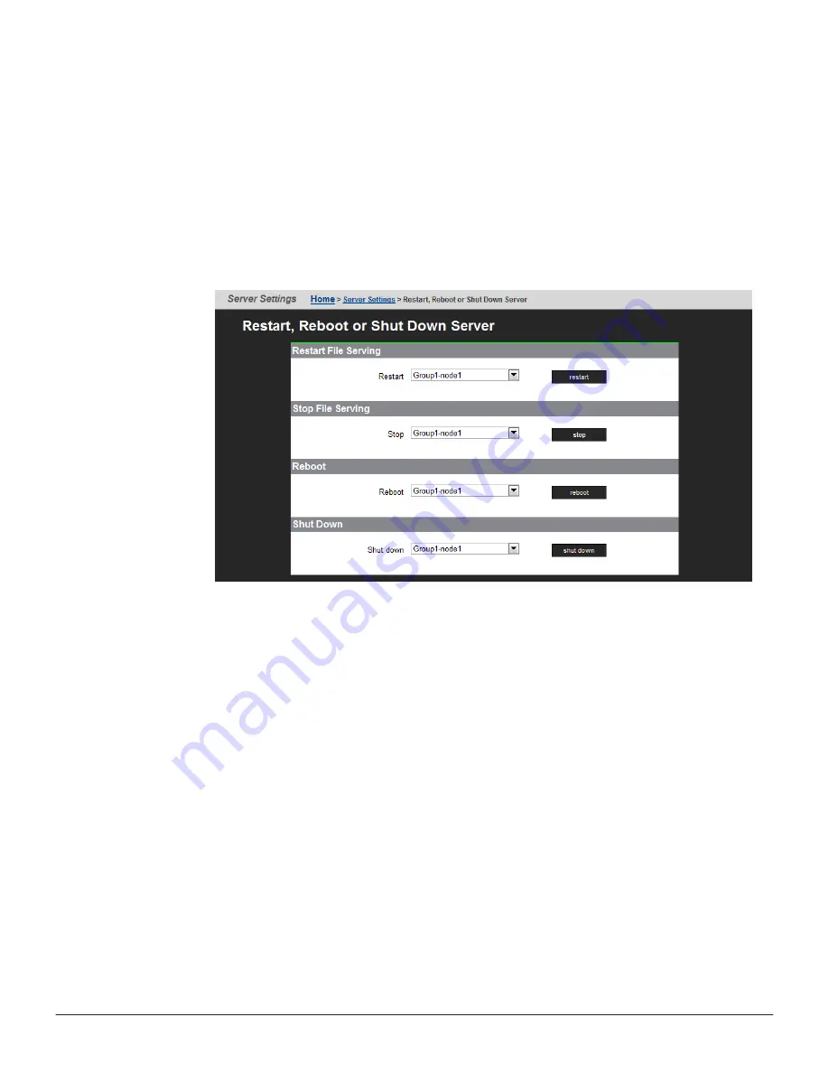
Using Web Manager, log in and select 

Reboot/Shutdown

 from the

Server Settings

 page to display the Restart, Reboot and Shutdown

page. Note that the page has different options depending on the

configuration of your system.


2.

Click the button for the action you want to perform as described next:

Configuring cipher suites

Configuring the SSL/TLS version

Obtaining and importing a CA-signed certificate

Click 

restart

 to restart all file serving EVSs on the server.

• Click 

stop

 to stop file all serving EVSs on the server.

• Click 

Reboot

 to stop file serving EVSs on the server, and then reboot

the entire server. Note that rebooting may take up to five minutes.

• Click 

Shutdown

 to stop file serving EVSs on the server, and then shut

down and power off the server.

70

Rebooting, shutting down, and powering off

Hitachi NAS Platform 3080 and 3090 G1 Hardware Reference

Содержание 3080 G1

Страница 1: ...Hitachi NAS Platform 3080 and 3090 G1 Hardware Reference Release 13 0 MK 92HNAS016 10 October 2016 ...

Страница 2: ...m authorized employees and other individuals to access relevant data and 2 Verifying that data continues to be held retrieved deleted or otherwise processed in accordance with relevant laws Notice on Export Controls The technical data and technology inherent in this Document may be subject to U S export control laws including the U S Export Administration Act and its associated regulations and may...

Страница 3: ...ory regulations 23 International standards 24 Federal Communications Commission FCC 24 European Union EU Statement 25 Canadian Department of Communication Compliance Statement 25 Avis de conformité aux normes du ministère des Communications du Canada 26 Radio Protection for Germany 26 Food and Drug Administration FDA 26 Chinese RoHS Compliance Statement 26 4 System overview 29 System components 30...

Страница 4: ...ont bezel 50 Bezel removal 50 Replacing a fan 50 Replacing the NVRAM backup battery pack 52 Removing the battery pack from the caddy 52 Removing the battery pack type 1 chassis 54 Inserting the new battery pack type 1 chassis 55 Removing the battery pack type 2 chassis 57 Inserting the new battery pack type 2 chassis 60 Collecting system backups and diagnostics 62 Resetting the battery age and res...

Страница 5: ...g an internal SMU if necessary 108 Replacing a single server with an embedded SMU 108 Obtaining backups diagnostics firmware levels and license keys 109 Shutting down the server you are replacing 111 Configuring the replacement server 111 Finalizing and verifying the replacement server configuration 113 Replacing a single server with an external SMU 115 Obtaining backups diagnostics firmware level...

Страница 6: ...6 Hitachi NAS Platform 3080 and 3090 G1 Hardware Reference ...

Страница 7: ...er Command Line Reference Command Line Reference for models 4060 4080 and 4100 Command Line Reference for models 3080 and 3090 Administration Guides System Access Guide MK 92HNAS014 Explains how to log in to the system provides information about accessing the NAS server cluster CLI and the SMU CLI and provides information about the documentation help and search capabilities available in the system...

Страница 8: ...ntivirus Administration Guide MK 92HNAS004 Describes the supported antivirus engines provides information about how to enable them and how to configure the system to use them Backup Administration Guide MK 92HNAS007 Provides information about configuring the server to work with NDMP and making and managing NDMP backups Note For a complete list of Hitachi NAS open source software copyrights and lic...

Страница 9: ...ommunication switch Best Practices for Hitachi NAS Universal Migrator MK 92HNAS047 The Hitachi NAS Universal Migrator UM feature provides customers with a convenient and minimally disruptive method to migrate from their existing NAS system to the Hitachi NAS Platform The practices and recommendations outlined in this document describe how to best use this feature Hitachi Data Systems SU 12 x Netwo...

Страница 10: ...m Accessing product documentation Product user documentation is available on Hitachi Data Systems Support Connect https knowledge hds com Documents Check this site for the most current documentation including important updates that may have been made after the release of the product Getting help Hitachi Support Connect is the destination for technical support of products and solutions sold by Hita...

Страница 11: ...Thank you Preface 11 Hitachi NAS Platform 3080 and 3090 G1 Hardware Reference ...

Страница 12: ...12 Preface Hitachi NAS Platform 3080 and 3090 G1 Hardware Reference ...

Страница 13: ...to install and configure the hardware and software and how to replace faulty components The following server models are covered 3080 and 3090 For assistance with storage arrays connected to the server refer to the Storage Subsystem Administration Guide Audience Conventions About this manual 13 Hitachi NAS Platform 3080 and 3090 G1 Hardware Reference ...

Страница 14: ...This bold fixed space font denotes literal items that the user enters in interactive sessions Output is shown in nonbold fixed space font and Brackets enclose optional portions of a command or directive line Ellipses indicate that a preceding element can be repeated GUI element This font denotes the names of graphical user interface GUI elements such as windows screens dialog boxes menus toolbars ...

Страница 15: ...ng DEUTSCH Die folgenden Symbole werden in diesem Handbuch zur Anzeige von Sicherheitshinweisen verwendet Lesen Sie die so gekennzeichneten Informationen durch um die erforderlichen Maßnahmen zu ergreifen Anmerkung Mit einer Anmerkung wird auf Informationen verwiesen die Sie beachten sollten VORSICHT Das Wort Vorsicht weist auf mögliche Schäden für Daten oder Ihre Ausrüstung hin Sie sollten erst d...

Страница 16: ...le Operazioni preliminari ITALIANO Le seguenti icone vengono utilizzate nella guida a scopo cautelativo Prima di procedere Vi viene richiesta un attenta lettura di tutte le procedure contrassegnate dalle suddette icone affinché vengano applicate correttamente Suggerimento Suggerimento fornisce indicazioni supplementari comunque utili allo scopo ATTENZIONE Attenzione indica il potenziale danneggiam...

Страница 17: ...iste um possível risco para a segurança pessoal Ennen kuin aloitat SUOMI Seuraavilla kuvakkeilla kiinnitetään tässä oppaassa huomiota turvallisuusseikkoihin Näillä kuvakkeilla merkityt menettelytavat tulee lukea ja ymmärtää ennen jatkamista Huomautus Huomautus sisältää tietoja jotka tulee ottaa huomioon VAROITUS Varoitus varoittaa tietojen tai laitteiden vahingoittumisen mahdollisuudesta Tällä mer...

Страница 18: ...18 About this manual Hitachi NAS Platform 3080 and 3090 G1 Hardware Reference ...

Страница 19: ...ety guidelines to follow when working with the equipment Electrostatic discharge precautions Safety and handling precautions Electrical precautions Data protection precautions Safety information 19 Hitachi NAS Platform 3080 and 3090 G1 Hardware Reference ...

Страница 20: ...ing all storage enclosures from the bottom to the top Do not remove more than one unit from the rack at a time To help prevent serious injuries load the components in the storage cabinet in the prescribed order 1 If present install the rack stabilizer plate to the front of the system cabinet 2 Load the Fibre Channel FC switches in the storage cabinet at the positions recommended in the System Inst...

Страница 21: ...g power Only operate the equipment from nominal mains input voltages in the range 100 240Vac 6A max 50 60Hz Caution Turn off all power supplies or remove all power cords before undertaking servicing of the system Unplug a system component if it needs to be moved or if it is damaged Note For additional data protection Hitachi recommends that you use an external UPS to power the server Also each of ...

Страница 22: ...y and speed Always shut down the system before it is moved switched off or reset All storage enclosures are fitted with optical SFP transceivers The transceivers that are approved for use with supported storage enclosures vary depending on the unit The transceivers qualified for older systems might not be approved for use with the most current storage systems To ensure proper operation of the serv...

Страница 23: ...re that regulatory compliance requirements are met International standards Federal Communications Commission FCC European Union EU Statement Canadian Department of Communication Compliance Statement Radio Protection for Germany Food and Drug Administration FDA Chinese RoHS Compliance Statement Mandatory regulations 23 Hitachi NAS Platform 3080 and 3090 G1 Hardware Reference ...

Страница 24: ...ertification by CoC Federal Communications Commission FCC This equipment has been tested and found to comply with the limits for a Class A digital device pursuant to Part 15 of the FCC Rules These limits are designed to provide reasonable protection against harmful interference when the equipment is operated in a commercial environment This equipment generates uses and can radiate radio frequency ...

Страница 25: ...tion in the use of Certain Hazardous Substances in Electrical and Electronic Equipment RoHS This product is 6 6 fully compliant The manufacturer cannot accept responsibility for any failure to satisfy the protection requirements resulting from a non recommended modification of the product This product has been tested and found to comply with the limits for Class A Information Technology Equipment ...

Страница 26: ...iel brouilleur du Canada Radio Protection for Germany Dieses Gerät erfüllt die Bedingungen der EN 55022 Klasse A Food and Drug Administration FDA The product complies with FDA 21 CFR 1040 10 and 1040 11 regulations which govern the safe use of lasers Chinese RoHS Compliance Statement 26 Mandatory regulations Hitachi NAS Platform 3080 and 3090 G1 Hardware Reference ...

Страница 27: ...Mandatory regulations 27 Hitachi NAS Platform 3080 and 3090 G1 Hardware Reference ...

Страница 28: ...28 Mandatory regulations Hitachi NAS Platform 3080 and 3090 G1 Hardware Reference ...

Страница 29: ...chi NAS Platform server system for the following models Hitachi NAS Platform Model 3080 Hitachi NAS Platform Model 3090 System components Server specifications Attaching a rack stabilizer plate System overview 29 Hitachi NAS Platform 3080 and 3090 G1 Hardware Reference ...

Страница 30: ...r components in a system An SMU provides administration and monitoring tools It supports data migration and replication and acts as a quorum device in a cluster configuration Although integral to the system the SMU does not move data between the network client and the servers In a single server configuration typically an embedded SMU manages the system In clustered systems and some single node sys...

Страница 31: ...about the availability of those switches Hitachi Data Systems requires dual 10 GbE switches for redundancy In a dual switch configuration if one switch fails the cluster nodes remain connected through the second switch Server specifications The following specifications are for the server Except for the power and cooling values these specifications do not reflect differences among models they are t...

Страница 32: ...at up to 0 53 Grms as per ASTM D4728 Altitude Maximum of 2000 meters Attaching a rack stabilizer plate A rack stabilizer plate and mounting hardware are supplied with some system configurations Hitachi Data Systems recommends that you always use the stabilizer plate when provided Use of a stabilizer plate is required for those installations with dense trays The stabilizer contains two holes for se...

Страница 33: ...tion about the physical configuration of a cluster configuration see the Hitachi NAS Platform and Hitachi Unified Storage File Module System Installation Guide The Hitachi NAS Platform server chassis consists of A removable fascia MMB Mercury Motherboard MFB Mercury FPGA Board Two hot swappable fan assemblies Dual power supplies NVRAM backup battery pack Dual 2 5 inch disk drives Introducing the H...

Страница 34: ...he server for repair boards are not field replaceable Field replaceable units FRUs include power supplies an NVRAM backup battery pack fan assemblies and disk drives For more information see Replacing server components on page 49 Ventilation There are vents and fan openings on the front and the rear of the server These openings are designed to allow airflow which prevents the server from overheati...

Страница 35: ...r all EVSs are running on the other node in a cluster Fast flash five flashes per second The server is rebooting Off The server is not powered up Table 2 Server status LED amber LEDs Meaning Amber Critical failure and the server is not operational Slow flash once every three seconds System shutdown has failed Flashes once every three seconds Medium flash once every 8 seconds The server needs atten...

Страница 36: ...ake up to 24 hours to complete During the conditioning cycle the full NVRAM content backup protection time of 72 hours cannot be guaranteed A replacement battery pack may not be fully charged it may not be at 100 capacity when it is installed After a new battery pack is installed the server performs tests and starts a conditioning cycle which may take up to 24 hours During the conditioning cycle t...

Страница 37: ...he flashing NVRAM LED the battery can be manually isolated using the reset button See Reset button RST on page 41 for the location of the reset button When preparing a server for shipment or if it will be powered down for any length of time it is important that the server has been shut down correctly before powering off Otherwise if the server is improperly shut down the batteries supplying the NV...

Страница 38: ...o 10 GbE switch 2 10 GbE network ports 2 Connection to external 10 Gbps Ethernet data network 3 Gigabit Ethernet network ports 6 Connection to external Ethernet data network 4 10 100 Ethernet port 5 Connection to private management network 5 Storage or FC switch 4 Connection to disk arrays or where present to the FC switches 6 n a 3 Status LEDs NVRAM power and server and Power and Reset buttons 7 ...

Страница 39: ...ar panel of the server contains three 3 status LEDs that indicate server status and two buttons that are used to power up and reset the server Figure 2 Rear panel server status LEDs and buttons Table 4 Rear panel status LEDs and buttons Item Description 1 NVRAM battery backup status LED 2 Power status symbol and LED 3 Server status LED 4 Reset button 5 Power button Rear panel LED state description...

Страница 40: ...other node in a cluster Fast flash five flashes per second The server is rebooting Off The server is not powered up Table 7 Server status LED amber LEDs Meaning Amber Critical failure and the server is not operational Slow flash once every three seconds System shutdown has failed Flashes once every three seconds Medium flash once every 8 seconds The server needs attention and a non critical failur...

Страница 41: ...button does not guarantee a complete shutdown before rebooting Only press the reset button when the server is powered on to recover a server which has become unresponsive Pressing the reset button at this time may produce a dump automatically Pressing the reset button for more than five seconds when the server is not powered up disables the NVRAM battery pack which may be necessary prior to shippi...

Страница 42: ...shing Network activity Amber off No network activity 10 Gigabit Ethernet customer data network ports The 10 Gigabit Ethernet GbE customer data network ports are used to connect the server or cluster node to the customer s data network also called the public data network These ports may be aggregated into a 1 2 3 or 4 aggregated port See the Network Administration Guide for more information on crea...

Страница 43: ...speeds of up to one 1 gigabit per second and require the use of a standard RJ45 cable connector The GE Customer Ethernet Network ports are labeled as shown next Figure 6 GE Customer Ethernet Network Ports Label Once connected each GE port has two indicator LEDs one green and one amber These LEDs provide link status and network activity status information as follows Status Activity Per Port Meaning...

Страница 44: ...tatus and network activity status information as follows Status Activity Per Port Meaning Status Green On not flashing 10 or 100 Mbps link present Green Off No link Activity Amber Flashing Network activity Amber Off No network activity Fibre channel storage ports The Fibre Channel FC storage ports allow you to connect the server with other FC devices such as storage subsystems FC ports operate at ...

Страница 45: ... Power supply units The server has dual hot swappable load sharing AC power supply units PSUs The PSUs are accessible from the rear of the server The server monitors the operational status of the power supply modules so that the management interfaces can indicate the physical location of the failed PSU LED indicators provide PSU status information for the state of the PSU Figure 9 Power supply uni...

Страница 46: ...9 PSU status LED amber Status Meaning Off PSU operating normally Amber PSU internal failure over temperature fan or internal component If the PSU status LED is on unplug the power cable wait 10 minutes then reconnect the cable If the PSU Status LED remains off the PSU has failed and must be replaced See Replacing a power supply unit on page 67 for more information on replacing a PSU Table 10 AC po...

Страница 47: ...nect the server or node to the customer facing management network and the private management network or to connect directly to another device for management purposes The 10 100 1000 Ethernet ports operate at speeds of up to one 1 gigabit per second and require the use of a standard RJ45 cable connector Once connected each GE port has two indicator LEDs one on the top left and the second on the top...

Страница 48: ...be accessed through the network Any VT100 terminal emulation interface can be used to access to the CLI so that you can perform management or configuration functions Connect the terminal to the serial port on the rear panel of the server then set the host settings to the values shown in the following table to ensure proper communication between the terminal and the server Table 11 Host setting val...

Страница 49: ...ose components The section also describes which components are hot swappable Removing and replacing the front bezel Bezel removal Replacing a fan Replacing the NVRAM backup battery pack Replacing a hard disk Replacing a power supply unit Replacing server components 49 Hitachi NAS Platform 3080 and 3090 G1 Hardware Reference ...

Страница 50: ...k airflow to be consistent with other storage system components The server continues to operate following the failure of a single fan and during the temporary removal of a fan for replacement A failed fan must be replaced as soon as possible The fans are contained within three assemblies which are located behind the front fascia and are removable from the front of the server All servers have three...

Страница 51: ... and place it in a safe location Note that the upper fan retention bracket helps to hold all three fan assemblies in position Figure 12 Fan Retention Brackets 5 For each fan assembly you are replacing remove the lower fan retention bracket and place it in a safe location 6 Remove the faulty fan assembly and put the new fan assembly into place Make sure to Fit the new fan assembly in the same orien...

Страница 52: ...procedure there will be a period of time when the NVRAM contents are not backed up by the battery pack If a power failure occurs during this period the NVRAM contents may be lost The server uses one of two types of chassis Type 1 Without a battery retention bracket Type 2 With a battery retention bracket This section explains how to change the battery pack in both types of chassis Note Replacement...

Страница 53: ...he battery pack from the caddy 4 Disconnect the battery from the caddy by pressing down on the retention clip that holds the connector together and then separating the connector The metal portion of the module can be returned to the supplier or be discarded Replacing server components 53 Hitachi NAS Platform 3080 and 3090 G1 Hardware Reference ...

Страница 54: ... pack present 2 Remove the fascia see Bezel removal on page 50 for more information 3 Gently slide the old battery pack out of the server 4 Disconnect the battery a Carefully push in on the retention clip b Carefully pull the connector away from the socket 54 Replacing server components Hitachi NAS Platform 3080 and 3090 G1 Hardware Reference ...

Страница 55: ...al regulations or return it to the battery pack supplier Inserting the new battery pack type 1 chassis Procedure 1 Plug the connector in before inserting the new battery pack The connector plug must be positioned so that the retention clip is on the left side before pushing it in as shown Replacing server components 55 Hitachi NAS Platform 3080 and 3090 G1 Hardware Reference ...

Страница 56: ...s on the left side b Make sure that the retention clip is aligned with the tab on the chassis receptacle c Insert the battery connector into the chassis receptacle and push until the retention clip locks onto the retention tab Do not force the plug in When correctly aligned it will slide in easily 3 Carefully insert the battery pack Ensure that the print is facing left and the cable is on the bott...

Страница 57: ... that it is along the right side of the battery compartment It must be fully behind the fascia mounting tab and the LED mounting tab 5 Check the battery connector to make sure the batter is plugged in correctly 6 Go to Collecting system backups and diagnostics on page 62 Removing the battery pack type 2 chassis Remove the NVRAM battery backup pack type 2 bracket Replacing server components 57 Hita...

Страница 58: ...oving the battery pack from the caddy on page 52 2 Remove the fascia 3 Disconnect the battery connector located on the right side of the battery compartment 58 Replacing server components Hitachi NAS Platform 3080 and 3090 G1 Hardware Reference ...

Страница 59: ...ping the battery pack connector do not pull on the wires 4 Remove the battery retention bracket 5 Gently remove the old battery pack from the compartment Replacing server components 59 Hitachi NAS Platform 3080 and 3090 G1 Hardware Reference ...

Страница 60: ...ions or return it to the battery pack supplier Inserting the new battery pack type 2 chassis Procedure 1 Insert the battery pack with the connector cable on the bottom and the printing on the left side Note Do not connect the battery connector yet 2 Fit the left side of the battery retention bracket into the slot 60 Replacing server components Hitachi NAS Platform 3080 and 3090 G1 Hardware Referen...

Страница 61: ... proceeding to the next step make sure that the clip is on the left 5 To connect the battery a Position the battery connector so that the retention clip is on the left side Replacing server components 61 Hitachi NAS Platform 3080 and 3090 G1 Hardware Reference ...

Страница 62: ...and the LED mounting tab 7 Check the battery connector to make sure the battery is plugged in correctly 8 Install the fascia or bezel the server cover 9 Go to Collecting system backups and diagnostics on page 62 Collecting system backups and diagnostics After replacing the battery collect system backups and diagnostics Procedure 1 Connect to the back end HNAS Private Management Switch 2 Open a bro...

Страница 63: ...r e Verify that the archive file can be opened and the contents can be extracted f If the archive file contains the words MISSING_FILES repeat step 6 If this does not resolve the issue then check that both nodes are fully operational and resolve any issues identified before repeating the procedure Resetting the battery age and restarting the chassis monitor Reset the battery age and Restart the Ch...

Страница 64: ...LY ONE of the following procedures If the node firmware is below 11 1 3225 02 perform the following procedure a Type the command new battery fitted field confirm b Once the prompt returns press ctrl d to exit out of BALI into the Linux Layer c Type su to change the login to root d Password nasadmin e Restart the chassis monitor by issuing the command etc init d chassis monitor restart f Type scc l...

Страница 65: ...ad both the diagnostic taken in the beginning of the procedure and this diagnostic to TUF using the SR for the battery replacement Replacing a hard disk If necessary either of the hard disks in the server can be replaced Do not attempt to replace a hard disk unless instructed to do so by customer support Hard disk replacement is not a hot swap operation replacing a hard disk requires that the serv...

Страница 66: ...s into a slot on the chassis floor on the left side a Remove the thumbscrew on the right side of the hard disk carrier b Gently lift the right side of the hard disk about 1 8 inch 1 4 centimeter and slide the disk carrier to the right c Once the disk carrier is completely disengaged from the chassis remove it from the server 8 Install the replacement hard disk Note The replacement hard disk should...

Страница 67: ...e script opt raid monitor bin recover replaced drive sh which will partition the disk appropriately update the server s internal RAID configuration and initiate rebuilding the RAID pair Rebuilding the RAID pair ensures all data is accurate across both hard disks After the script has finished no further interaction is required The RAID system rebuilds the disk as a background operation and events a...

Страница 68: ... the PSU from the chassis 4 Insert the replacement PSU The retention latch should click into position all the way to the left when the PSU is fully inserted If the PSU that is not being replaced is receiving mains power when the replacement PSU is fitted the fan on the replacement PSU becomes active 5 Connect the power cord to the back of the PSU The PSU should start as soon as the power connectio...

Страница 69: ...e for details about server software licenses Rebooting or shutting down a server Rebooting or shutting down a cluster Restarting an unresponsive server Powering down the server for maintenance Powering down the server for shipment or storage Recovering from power standby Rebooting shutting down and powering off 69 Hitachi NAS Platform 3080 and 3090 G1 Hardware Reference ...

Страница 70: ...erform as described next Configuring cipher suites Configuring the SSL TLS version Obtaining and importing a CA signed certificate Click restart to restart all file serving EVSs on the server Click stop to stop file all serving EVSs on the server Click Reboot to stop file serving EVSs on the server and then reboot the entire server Note that rebooting may take up to five minutes Click Shutdown to ...

Страница 71: ...on all nodes option and then click restart Stop File Serving To stop all file serving EVSs on a single node select the Stop file serving on node option use the drop down list to select a node and then click stop To stop all file serving EVSs on all cluster nodes select the Stop file serving on all nodes option and then click stop Reboot To reboot a single node select the Reboot node option use the...

Страница 72: ... software 2 From the siconsole select the server If the system fails to respond go to step 3 If the system takes you to the server OS console issue the command bt active so you can view the display If you are still at the siconsole select q press Return and then perform the following steps 1 Connect directly to the MMB as manager using ssh 2 If the connection succeeds you are taken to the server O...

Страница 73: ...al screen is blank press the Reset button Note Pulling the power cord from the server is not recommended Do not pull the power cord unless it is absolutely necessary First complete the steps above Powering down the server for maintenance This procedure should be followed whenever a server is to be powered down and will be left off for less than a day If however the system is being rebooted this pr...

Страница 74: ...own ship powerdown 2 Wait until the console displays the message Information Server has shut down and the rear panel LEDs turn off Note The PSUs continue to run and the PSU LEDs stay on 3 Power down the server by removing the power cables from the PSU modules 4 Wait 10 15 seconds then check that the NVRAM Status LED on the rear panel of the server is off If the NVRAM status LED is off the battery ...

Страница 75: ...powerdown command has been issued The PWR button was pressed when the server is running The server has shut down automatically due to an over temperature condition You can restore the server to its normal power state by either of the following methods Pressing the PWR button Remove the power cables from both PSUs wait for 10 seconds then reconnect the cables to the PSUs Rebooting shutting down and...

Страница 76: ...76 Rebooting shutting down and powering off Hitachi NAS Platform 3080 and 3090 G1 Hardware Reference ...

Страница 77: ...ard disk replacement Requirements for hard disk replacement Overview of the Procedure Accessing Linux on the server and node Step1 Performing an Internal Drive Health Check Step 2 Gathering information about the server or node Step 3 Backing up the server configuration Step 4 Locating the server Step 5 Save the preferred mapping and migrate EVSs cluster node only Step 6 Replacing a Server s Intern...

Страница 78: ...Step 8 Replacing the server s second disk Step 9 Synchronizing the second new disk Step 10 Restore EVSs cluster node only 78 Hard disk replacement Hitachi NAS Platform 3080 and 3090 G1 Hardware Reference ...

Страница 79: ...ely 2 5 hours and the server will be offline during this time You could restore services in approximately 1 5 hours by restoring services before the second disk of the server s RAID subsystem has completed synchronizing Caution Early service restoration is not recommended If the second disk of the internal RAID subsystem has not completed synchronizing and there is a disk failure you may lose data...

Страница 80: ... before beginning the hard disk replacement procedure Refer to the Server and Cluster Administration Guide for more information on upgrading firmware The password for the manager supervisor and root user accounts on the server with the hard disks to be replaced A maintenance period as described in Downtime considerations for hard disk replacement on page 79 Access to the Linux operating system of ...

Страница 81: ...nd new disk on page 101 10 For cluster nodes restore migrated EVSs to their preferred node See Step 10 Restore EVSs cluster node only on page 101 When performing parts of the disk replacement process you must access the Linux operating system and or the Bali console of the NAS server node Instructions on how to access these components are provided in Accessing Linux on the server and node on page ...

Страница 82: ...S 2 Enter the password for the manager user account By default the password for the manager account is nasadmin but this password might have been changed This logs you into the Bali console 3 Access the Linux prompt by exiting the Bali console Enter the following command exit or press the Ctrl D keys 4 Log in as the root user Enter the following command su password where password is the password f...

Страница 83: ...r Enter the following command su password where password is the password for the root user account You are now at the Linux prompt Step1 Performing an Internal Drive Health Check The health check evaluates both internal disks to determine if there are any pending disk failures Perform the health check twice Approximately one week before hard disk replacement to allow time to resolve any errors bef...

Страница 84: ...011 06 27 12 17 pci 0000 00 1f 2 scsi 0 0 0 0 part5 sda5 lrwxrwxrwx 1 root root 10 2011 06 27 12 17 pci 0000 00 1f 2 scsi 0 0 0 0 part6 sda6 lrwxrwxrwx 1 root root 9 2011 06 27 12 17 pci 0000 00 1f 2 scsi 2 0 0 0 sdb lrwxrwxrwx 1 root root 10 2011 06 27 12 17 pci 0000 00 1f 2 scsi 2 0 0 0 part1 sdb1 lrwxrwxrwx 1 root root 10 2011 06 27 12 17 pci 0000 00 1f 2 scsi 2 0 0 0 part2 sdb2 lrwxrwxrwx 1 ro...

Страница 85: ...tus 0 The previous self test routine completed without error or no self test has been run Total time to complete Offline data collection 634 seconds Offline data collection capabilities 0x7b SMART execute Offline immediate Auto Offline data collection on off support Suspend Offline collection upon new command Offline surface scan supported Self test supported Conveyance Self test supported Selecti...

Страница 86: ... 7 Seek_Error_Rate 0x000f 065 060 030 Pre fail Always 3326385 9 Power_On_Hours 0x0032 100 100 000 Old_age Always 156 10 Spin_Retry_Count 0x0013 100 100 097 Pre fail Always 0 12 Power_Cycle_Count 0x0032 100 100 020 Old_age Always 13 184 Unknown_Attribute 0x0032 100 100 099 Old_age Always 0 187 Reported_Uncorrect 0x0032 100 100 000 Old_age Always 0 188 Unknown_Attribute 0x0032 100 100 000 Old_age Al...

Страница 87: ...error 00 119 3 Short offline Completed without error 00 94 4 Short offline Completed without error 00 70 5 Extended offline Completed without error 00 46 6 Short offline Completed without error 00 21 If you find that one disk has no errors but the other disk does have errors replace the disk with errors first If you find errors on both disks contact technical support and provide them with the smar...

Страница 88: ...btain this information Procedure 1 Log in to the Bali console See Accessing Linux on the server and node on page 81 2 Select the server or node that has the disks you want to replace 3 Record the IP Address of the system you choose 4 Run the evs list command For a single node cluster or a standalone server record the administrative services EVS IP address 88 Hard disk replacement Hitachi NAS Platf...

Страница 89: ...Synchronized 1 Good 3 12302144 463572 Synchronized 2 Good 0 0 0 Synchronized Success For each device the Status should be Good and the Rebuild should be Synchronized If the values are correct repeat the health check as described in Step1 Performing an Internal Drive Health Check on page 83 If the values are not correct run the trouble chassis drive command If the command response displays No fault...

Страница 90: ...t Ethernet switch using an Ethernet cable 2 Log in to Web Manager 3 Navigate to Home Server Settings Configuration Backup Restore 4 Click backup to save the configuration file to your laptop 5 Verify that the backup file is complete and make sure the file size is not 0 bytes Step 4 Locating the server Before shutting down the server node to replace disks you must physically locate the server Proce...

Страница 91: ...ping Saving the current EVS to cluster configuration as the preferred mapping helps when restoring EVSs to cluster nodes For example if a failed cluster node is being restored the preferred mapping can be used to restore the original cluster configuration Procedure 1 Connect your laptop to the customer s network 2 Using a browser go to http SMU_IP_Address where SMU_IP_Address is the IP address of ...

Страница 92: ... the preferred mapping has been defined The current mapping is displayed in the Current EVS Mappings column of the EVS Mappings section of the page 6 Save the current EVS to cluster node mapping by clicking Save current as preferred in the EVS Mappings section 7 Migrate EVSs as required To migrate all EVSs between cluster nodes a Select Migrate all EVS from cluster node ___ to cluster node ___ 92 ...

Страница 93: ...rate Step 6 Replacing a Server s Internal Hard Disk Because physically replacing hard disks is not a hot swap operation you must shut down the server and disconnect the power cables from the PSUs before beginning physical replacement Procedure 1 Shut down the server Using Web Manager go to the Server Settings page and For a cluster node navigate to Home Restart Reboot or Shutdown Server Shutdown F...

Страница 94: ... Remove the fan Typically hard disk B is replaced before hard disk A Hard disk B is behind fan assembly number 2 the center fan Hard disk A is behind fan assembly number 1 the left fan Caution After one hard disk is replaced you must restart the server and resynchronize its internal RAID subsystem before replacing the second hard disk See Step 7 Synchronizing server s new disk on page 100 for more...

Страница 95: ...y When replacing hard disk A remove the upper fan retention bracket and the lower fan assembly bracket under fan assembly 1 the left fan assembly 8 Remove the fan assembly covering the disk you want to replace When replacing hard disk B remove fan assembly 2 the center fan assembly Hard disk B should now be visible Hard disk replacement 95 Hitachi NAS Platform 3080 and 3090 G1 Hardware Reference ...

Страница 96: ... into slots on the chassis floor on the left side Note The carrier used for replacement hard disks may be different than the carrier holding the old hard disks The new carriers fit into the same place and in the same way as the older carriers 96 Hard disk replacement Hitachi NAS Platform 3080 and 3090 G1 Hardware Reference ...

Страница 97: ...nted through the bottom plate of the carrier 9 Disconnect the power and SATA cables from the hard disk 10 Loosen the thumbscrew on the right side of the hard disk carrier Note that the thumbscrew cannot be removed from the carrier Hard disk replacement 97 Hitachi NAS Platform 3080 and 3090 G1 Hardware Reference ...

Страница 98: ...he chassis remove it from the server label it appropriately for example server X disk A and store it in a safe location 13 To install the replacement hard disk lift the right side of the carrier until you can insert the tabs on the left side of the disk carrier into the slots on the floor of the server chassis 98 Hard disk replacement Hitachi NAS Platform 3080 and 3090 G1 Hardware Reference ...

Страница 99: ...stud 15 Tighten the thumbscrew to secure the disk carrier Do not over tighten the thumbscrew 16 Connect the power and SATA cables to the replacement hard disk 17 Reinstall the fan in the mounting slot with the cable routed through the chassis cut out Hard disk replacement 99 Hitachi NAS Platform 3080 and 3090 G1 Hardware Reference ...

Страница 100: ... 4 Run the chassis drive status command and look at the values in the Status and Rebuild columns for each device The values in the Status column should be Invalid The Rebuild column should not display any values 5 Run the script opt raid monitor bin recover replaced drive sh This script partitions the replacement disk appropriately updates the server s internal RAID configuration and initiates reb...

Страница 101: ...equired to synchronize the server s second hard disk Once the second hard disk is synchronized log out by entering the exit command or pressing the Ctrl D keys Step 10 Restore EVSs cluster node only If replacing the hard disks in a standalone server skip this step If replacing the hard disks in a cluster node return each of the EVSs to its preferred node the node with the replaced disks The prefer...

Страница 102: ...he SMU is managing one cluster and no standalone servers the main EVS Migration page appears 5 To return all EVSs to their preferred nodes If the preferred mapping was saved in Step 5 Save the preferred mapping and migrate EVSs cluster node only on page 91 click Migrate all to preferred in the EVS Mappings section If the preferred mapping was not saved migrate EVSs as required 102 Hard disk replac...

Страница 103: ...ond drop down list select the cluster node to which the EVSs will be migrated d Click Migrate To migrate a single EVS to a cluster node a Select Migrate EVS ____ to cluster node ___ b From the first drop down list select the cluster node to migrate c From the second drop down list select the cluster node to which the EVS will be migrated d Click Migrate Hard disk replacement 103 Hitachi NAS Platfo...

Страница 104: ...104 Hard disk replacement Hitachi NAS Platform 3080 and 3090 G1 Hardware Reference ...

Страница 105: ...er using an external SMU for management replacing only one node Two node cluster using an external SMU for management replacing both nodes Important This document does not treat migration scenarios between different configurations at the time of replacement Replacement procedure overview Manually installing an internal SMU if necessary Replacing a single server with an embedded SMU Replacing a sin...

Страница 106: ...when replacing one server in a cluster Note Replacement servers are shipped without an embedded system management unit SMU so you must have a SMU installed before you can connect to a standalone server You can use a KVM keyboard video and mouse device or a serial cable to connect to the serial port Bring both devices with you just in case both are needed when the unit arrives If you connect to the...

Страница 107: ...ually be replaced with a permanent key This is required for all field scenarios except when replacing a single node in a cluster Note If the scenario is a single node or all cluster node replacement use the span allow access command to attach the storage when the MAC ID changes Previous backups A system backup preserves two critical components of information SMU configuration Server configuration ...

Страница 108: ...U However once added to the cluster the internal SMU should be uninstalled smu uninstall from the CLI of the newly added node Note when added to a cluster the external SMU will disable the internal SMU on the replacement node but it is recommended to fully uninstall the internal SMU Procedure 1 Obtain a copy of the SMUsetup iso file and copy the file into tmp scp tmp SMUsetup iso 2 As root on the ...

Страница 109: ...els and license keys On the old server Procedure 1 If the server is online using Web Manager SMU GUI navigate to Home Server Settings Configuration Backup Restore click backup and then select a location to save the backup file Ensure you save the backup file to a safe location off platform so that you can access it after the storage system is offline The backup process performed by the embedded SM...

Страница 110: ...nd the Hitachi NAS Platform and Hitachi Unified Storage File Module System Installation Guide for release specific requirements 4 Navigate to Home Server Settings Firmware Package Management to verify the existing server SU firmware release level 5 Navigate to Home Server Settings License Keys to check the license keys to ensure you have the correct set of new license keys 110 Server replacement p...

Страница 111: ...lowing rear panel figure and table to identify and label the cabling placement on the existing server 5 If cables are not labeled label them before removing them from the server 6 Remove all cables from the server and remove the server from the rack 7 Remove the rail mounts from the old server and install them on the new server 8 Remove the battery from the old server and install it in the new ser...

Страница 112: ...1 stop bit No parity No flow control VT100 emulation 6 Log in as root default password nasadmin and enter ssc localhost to access the BALI level command prompt 7 Enter evs list to obtain the IP configuration for the server 8 Using a supported browser launch the Web Manager SMU GUI using either of the IP addresses acquired from the EVS list output 9 Click Yes and log in as admin default password na...

Страница 113: ...nel FC link speed varies according to the server model Use the appropriate speed for your model Model Fibre Channel link speed HNAS 3080 and 3090 4 Gbps On the replacement server Note The following steps show the FC link speed as 8 Gbps as an example Procedure 1 Navigate to Home Server Settings License Keys to load the license keys 2 Remove the previous license keys in the backup file and add the ...

Страница 114: ...st to verify the storage pools spans are accessible Note In this instance cluster is synonymous with the standalone server 11 Enter span list cluster uuids span_label to display the cluster serial number UUID to which the storage pool belongs The UUID is written into the storage pool s configuration on disk COD The COD is a data structure stored in every SD which provides information how the diffe...

Страница 115: ...s a guide in reestablishing the system manually The data and file systems will remain intact independent of the replacement and without a backup Note Replacement servers are shipped without an embedded system management unit SMU so you must have a SMU installed before you can connect to a standalone server Important Set expectations up front with the customer that this will delay time to recovery ...

Страница 116: ... requirements 4 Navigate to Home Server Settings License Keys to check the license keys to ensure you have the correct set of new license keys 5 Record the following information IP addresses for Ethernet ports 0 and 1 Gateway Domain name Host name Shutting down the server you are replacing On the server that you are replacing Procedure 1 From the server console issue the command shutdown ship powe...

Страница 117: ...move the bezel from the old server and install it on the new server 10 Insert the new server into the rack and connect the power cords to the power supplies Note Do not make any other cable connections at this time Configuring the replacement server Before you begin Obtain the necessary IP addresses to be used for the replacement server Servers shipped from the factory have not yet had the nas pre...

Страница 118: ...n for the server 8 Using a supported browser launch the Web Manager SMU GUI using either of the IP addresses acquired from the EVS list output 9 Click Yes to proceed past the Security Alert and log in as admin default password nasadmin 10 Verify and if necessary convert the new server to the model profile required This step requires a separate process training and license keys Contact Hitachi Data...

Страница 119: ... and verifying the replacement server configuration The Fibre Channel FC link speed varies according to the server model Use the appropriate speed for your model Model Fibre Channel link speed HNAS 3080 and 3090 4 Gbps On the replacement server Note The following steps show the FC link speed as 8 Gbps as an example Procedure 1 Navigate to Home Server Settings License Keys to load the license keys ...

Страница 120: ...used 9 Enter sd list to verify the system drives statuses as OK and access is allowed 10 Enter span list to verify the storage pools spans are accessible Note In this instance cluster is synonymous with the standalone server 11 Enter span list cluster uuids span_label to display the cluster serial number UUID to which the storage pool belongs The UUID is written into the storage pool s configurati...

Страница 121: ...ional state of the entire system beyond any single node failure Because you are replacing an existing node from a cluster you do not require any additional licenses since the cluster will retain the licenses used from the existing node and the Cluster MAC ID does not change even if you are replacing node 1 Capturing information from the existing node To start capture and record information from th...

Страница 122: ...xisting Admin IP address in the cluster will be used 4 Ensure that the new node boots and that you can connect to it via SSH and login to BALI 5 Use the CLI hport wwn command to get the WWN information for the new node Record the new WWN information for the new node WWN Information WWN Port 1 WWN Port 2 WWN Port 3 WWN Port 4 Preparing the old node for removal Prepare the old node for removal befor...

Страница 123: ...rity update this to reflect the changes that are being made to the WWN as you documented previously in Preparing the node step 5 5 Add the new node as a managed server on the SMU 6 From the drop down in the SMU select the existing Cluster 7 Go into Home Sever Settings Cluster Configuration and click on AddCluster node 8 Complete the add cluster node wizard selecting the new node which will appear ...

Страница 124: ...ot operating normally for any reason contact support for assistance 2 Navigate to Home Server Settings Cluster Configuration to verify the cluster configuration status Ensure that the cluster is shown as Online and Robust and has the correct number of nodes 3 Use CLI to verify that the new node has access to the System Drives Use sd list from the node that you have just replaced 124 Server replace...

Страница 125: ...0 1560 5 OK Yes 390 Pri FSS_AMS200 1560 6 OK Yes 390 Pri FSS_AMS200 1560 7 OK Yes 390 Pri FSS_AMS200 1560 4 If EVS mapping or balancing is required select the EVS to migrate assign it to the preferred node and then click migrate 5 To set the preferred node for any remaining EVSs navigate to Home Server Settings EVS Management EVS Details Server replacement procedures 125 Hitachi NAS Platform 3080 ...

Страница 126: ...ith an external SMU that are nonfunctioning and does not have a recent backup saved off platform then a challenging and manual recovery process is necessary If this circumstance is encountered call the support organization for a copy of the system s latest diagnostics files if available to be used as a guide in reestablishing the system manually The data and file systems will remain intact indepen...

Страница 127: ...ge system is offline The backup process performed by the embedded SMU will automatically capture both the SMU and server configuration files in one complete set 2 Navigate to Home Status Monitoring Diagnostics download to download the diagnostic test results Select the devices for which diagnostics are required by checking the appropriate boxes Then click download 3 Navigate to Home Server Setting...

Страница 128: ... servers that you are replacing Procedure 1 From the server console issue the command cn node shutdown ship powerdown where node represents the targeted node Wait until the console displays Information Server has shut down and the rear panel LEDs turn off The PSU and server fans continue to run until you remove the power cables from the PSU module See the appropriate system component section for m...

Страница 129: ... on the new server 10 Insert the new server into the rack and connect the power cords to the power supplies Note Do not make any other cable connections at this time Configuring the replacement servers Before you begin Obtain the necessary IP addresses to be used for the replacement server Servers shipped from the factory have not yet had the nas preconfig script run on them so a replacement serve...

Страница 130: ...process training and license keys Contact Hitachi Data Systems Support Center if the incorrect model arrives for replacement 11 Navigate to Home Server Settings Firmware Package Management to verify and if necessary upgrade the new server to the latest SU release 12 Navigate to Home Server Settings Cluster Wizard and promote the node to the cluster 13 Enter the cluster name cluster node IP address...

Страница 131: ...sed configuration and then download another diagnostic to support Permanent license keys for the new server will be provided within 15 days If the server is not operating normally for any reason contact support for assistance 2 Navigate to Home Status Monitoring Event Logs and then click Clear Event Logs 3 Confirm all final settings IP addresses customer contact information service restarts client...

Страница 132: ...132 Server replacement procedures Hitachi NAS Platform 3080 and 3090 G1 Hardware Reference ...

Страница 133: ...are required for EMEA units start with a S N starting with M2SEKW13 or higher SX325097 MK1 Battery Module ea System Management Unit SMU parts Part number Description Notes SX325094 SMU300 w CentOS 4 4 No SMU code RoHS5 SX325121 SMU300 HDS Branded CentOS6 2 No SMU code SX325134 SMU300 HDS Branded CentOS6 2 no SMU code RoHS 2013 Required for EMEA RoHS 2013 spares are required for EMEA units start wi...

Страница 134: ... VDX6730 16 F Brocade VDX 6730 10GbE Switch 16 Ports SFP AC Non Port Side Exhaust AF XBR 250WPSAC F Brocade VDX 6730 250W AC PS fan Non Port Side Exhaust XBR VDX6730 40 R Brocade VDX 6730 10GbE Switch 40 Ports SFP AC Port Side Exhaust AF XBR 500WPSAC R Brocade VDX 6730 500W AC PS Port Side Exhaust XBR FAN 80 R Brocade VDX 6730 80MM Fan assy Port Side Exhaust XBR VDX6730 40 F Brocade VDX 6730 10GbE...

Страница 135: ... switch part number HD TI 24X AC SX350004 SFP 1000BaseT Copper Manufacturer part number is FCMJ 8521 3 SX350000 SFP Multi Mode Fiber 2 Gbps Manufacturer part number is FTRJ8519P1BNL SX350010 SFP Multi Mode Fiber 4 Gbps Manufacturer part number is FTLF8524P2BNV SX350011 XFP 10G 850NM 1 Pk for Cluster only Manufacturer part number is FTLX8511D3 FTLX1412D3BCL Multi source XFP 10Gbps Single Mode 1310n...

Страница 136: ...136 Parts list for 3080 3090 G1 servers Hitachi NAS Platform 3080 and 3090 G1 Hardware Reference ...

Страница 137: ...Hitachi NAS Platform 3080 and 3090 G1 Hardware Reference ...

Страница 138: ... Santa Clara California 95050 2639 U S A www hds com Regional Contact Information Americas 1 408 970 1000 info hds com Europe Middle East and Africa 44 0 1753 618000 info emea hds com Asia Pacific 852 3189 7900 hds marketing apac hds com MK 92HNAS016 10 October 2016 ...

Отзывы: