7
English
(2) When the cut-off w heel contacts the cutting m aterial,
gently press dow n the handle further and start
cutting.
(3) When cutting (or designated slotting) is com pleted,
raise the handle and restore it to its original position.
(4) At the term ination of each cutting process, turn OFF
the sw itch to stop rotation and proceed w ith the
subsequent cutting job.
CAUTION
It does not necessarily cut rapidly w hen putting
m ore force on the handle.
Too m uch force on the handle w ill put excessive
pressure on the m otor and reduce its capacity.
Do not fail to sw itch OFF the sw itch after operation
is com pleted and pull the plug out.
M OUNTING AND DISM OUNTING THE CUT-
OFF WHEEL
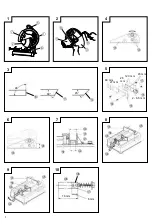
1. Dismounting the cut-off w heel (Fig. 2)
(1) Press the stopper and loosen the bolt w ith a hex.
bar w rench.
CAUTION
When the m ounting shaft for cut-off w heel cannot
be fixed w ith pressing the stopper, turn the bolt
w ith a hex. bar w rench w hile pressing the stopper.
The m ounting shaft for cut-off w heel is fixed w hen
the stopper has been low ered.
(2) Rem ove the bolt, w asher (A), and the w heel w asher
and detach the cut-off w heel.
2. M ounting the cut-off w heel
Throughly rem ove dust from the w heel w ashers
and bolt then m ount the w heel by follow ing the
dism ounting procedures in reverse order. Be sure
to attach the sub-cover at the end.
CAUTION
Confirm that the stopper w hich w as used for
installation and rem oval of the cut-off w heel has
returned to the retract position.
HOW TO OPERATE
1. Procedure for fixing the cutting material (Fig. 8
and 9)
Place the w orkpiece m aterial betw een vise (A) and
vise (B), raise the clutch and push the screw handle
to bring vise (A) lightly into contact w ith the
w orkpiece m aterial, as show n in Fig. 8.
Then, turn the clutch dow n, and securely fix the
w orkpiece m aterial in position by turning the screw
handle. When the cutting job is com pleted, turn the
screw handle 2 or 3 tim es to loosen the vise, and
rem ove the w orkpiece m aterial, as show n in
Fig. 9.
CAUTION
The w heel continues to rotate after the m achine is
sw itched off.
Never rem ove or install a w orkpiece m aterial w hile
the cut-off w heel is rotating, to avoid personal injury.
Long w orkpieces m ust be supported by blocks
nonflam m able m aterial on either side so that it be
level w ith the base top.
2. Cutting at angles (Fig. 3 and 4)
(1) The m achine perm its cutting at angles of 45° or 60°.
(2) Loosen the tw o M 10 hexagon socket head bolts on
the vice (B), then set the w orking surface on the
vice-jaw at any angles of 0°, 30°, or 45° as show n
in Fig. 4. Upon com pletion of setting, securely tighten
the tw o 10 m m bolts.
(3) When w ide m aterial is cut w ith angle, it w ill be
firm ly cam ped by fixing a steel board like Fig. 5
to the vise (B).
3. M oving the stationary vise-jaw (Fig. 6)
The vise opening is set at the m axim um of 170 m m
w hen shipped from the factory. In case an opening
of m ore than 170 m m is required, m ove the vise
to the position show n by the chain line after
unscrew ing the tw o bolts. The m axim um opening
can be set in tw o steps 205 m m and 240 m m . When
the cutting m aterial is excessively w ide, the vise can
be effectively used by repositioning the stationary
side of the vise-jaw s.
4. How to use metallic block (Fig. 7)
When the cut-off w heel has a reduced outer
diam eter, insert betw een the vise (A) and (B) a
m etallic block slightly sm aller than the dim ension
of w orkpiece being cut to use the cut-off w heel
econom ically.
M AINTENANCE AND INSPECTION
CAUTION
Be sure to sw itch off and pull off the plug from the pow er
outlet before inspection and m aintenance.
1. Replacing a cut-off w heel
When the cut-off w heel has already becom e dull
w hile continually using, the unnecessary load is got
from the m otor. Consequently, redress or replace
a dull cut-off w heel to ensure grinding efficiency.
2. Inspecting the carbon brushes (Fig. 10)
The M otor em ploys carbon brushes w hich are
consum able parts. When they becom e w orn to or
near the “ w ear lim it” , it could result in m otor trouble.
When an auto-stop carbon brush is equipped, the
m otor w ill stop autom atically. At that tim e, replace
both carbon brushes w ith new ones w hich have the
sam e carbon brush Num ber show n in the figure.
In addition, alw ays keep carbon brushes clean and
ensure that they slide freely w ithin the brush holders.
3. Inspecting the mounting screw s
Regularly inspect all m ounting screw s and ensure
that they are properly tightened. Should any of the
screw s be loose, retighten them im m ediately. Failure
to do so could result in serious hazard.
4. Lubrication
Supply oil in the follow ing oil supply points once
a m onth so as to keep the m achine w orkable for
a long tim e (See Fig. 1).
Oil supply points
䡬
Rotary part of shaft
䡬
Rotary part of vise
䡬
Slide w ay of vise (A)
5. Cleaning
Wipe off chip and w aste adhered to the m achine
w ith a cloth or the like tim e to tim e. Be careful not
to m ake the m otor portion w et w ith oil or w ater.
6. Faults in the m achine, including guards or cutter
blades, should be reported as soon as they are
discovered.

