
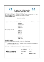


Models:
Water Source Units;
AVWW-76FKFW
AVWW-96FKFW
AVWW-114FKFW
AVWW-136FKFW
AVWW-154FKFW
AVWW-170FKFW
AVWW-190FKFW
AVWW-210FKFW
AVWW-228FKFW
AVWW-250FKFW
AVWW-268FKFW
AVWW-286FKFW
AVWW-304FKFW
AVWW-326FKFW
AVWW-344FKFW
AVWW-360FKFW
AVWW-380FKFW
AVWW-400FKFW
AVWW-418FKFW
AVWW-440FKFW
AVWW-456FKFW
AVWW-476FKFW
AVWW-494FKFW
AVWW-516FKFW
AVWW-534FKFW
AVWW-550FKFW
AVWW-570FKFW
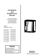
IMPORTANT:
READ AND UNDERSTAND
THIS MANUAL BEFORE
INSTALLING THIS HEAT PUMP AND
HEAT RECOVERY AIR CONDITIONER.
KEEP THIS MANUAL FOR
FUTURE REFERENCE.
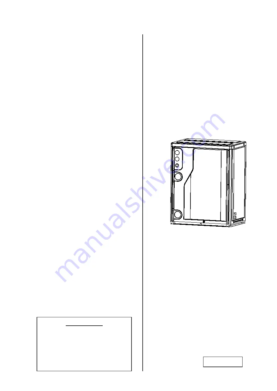
Installation
and
Maintenance
Manual
INVERTER-DRIVEN
MULTI-SPLIT SYSTEM
HEAT PUMP AND
HEAT RECOVERY
AIR CONDITIONERS
M00261Q
ORIGINAL INSTRUCTIONS
Содержание AVWW-114FKFW
Страница 2: ......