Installation OCTOPUS OS3
Release 01 02/2019
Technical support
https://hirschmann-support.belden.com
User Manual
Installation
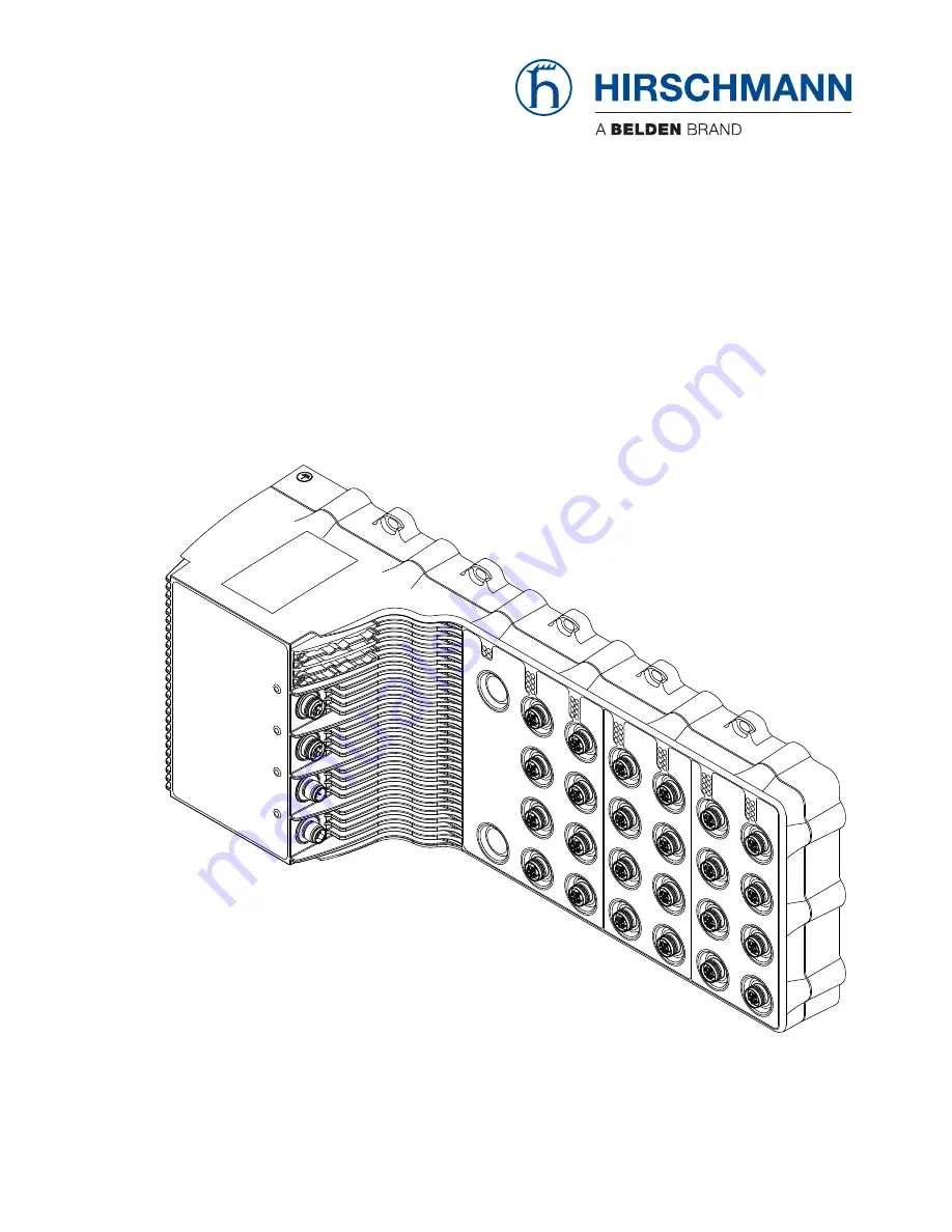
Managed Ethernet SwitchOCTOPUS OS3
Страница 1: ...Installation OCTOPUS OS3 Release 01 02 2019 Technical support https hirschmann support belden com User Manual Installation Managed Ethernet Switch OCTOPUS OS3...
Страница 2: ...ed here are binding only if they have been expressly agreed when the contract was made This document was produced by Hirschmann Automation and Control GmbH according to the best of the company s knowl...
Страница 3: ...ts 16 1 7 Display elements 17 1 7 1 Device state 17 1 7 2 Port Status 19 1 8 Management interfaces 20 1 8 1 V 24 interface external management 20 1 8 2 USB interface 20 1 9 Input output interfaces 21...
Страница 4: ...l contact 32 7 4 Power consumption power output 32 7 5 Climatic conditions during operation 33 7 6 Climatic conditions during storage 33 7 7 Dimension drawings 34 7 8 EMC and immunity 35 7 9 Network r...
Страница 5: ...e to Hirschmann for inspection National and international safety regulations Verify that the electrical installation meets local or nationally applicable safety regulations Certified usage Use the pro...
Страница 6: ...he device in such a way that it is protected against mechanical forces in the area of the power supply Device casing Only technicians authorized by the manufacturer are permitted to open the casing Ne...
Страница 7: ...trictions The connected voltage complies with the requirements for a safety extra low voltage SELV or ES1 as per IEC EN 62368 1 The connected voltage is limited by a current limitation device or a fus...
Страница 8: ...ctive s the EU conformity declaration will be at the disposal of the relevant authorities at the following address Hirschmann Automation and Control GmbH Stuttgarter Str 45 51 72654 Neckartenzlingen G...
Страница 9: ...se requirements are designed to provide sufficient protection against interference when the device is being used in a business environment The device creates and uses high frequencies and can also rad...
Страница 10: ...ion of the display and the other information that you need to install the device The following manuals are available on the Internet at https www doc hirschmann com as downloads User Manual Installati...
Страница 11: ...Installation OCTOPUS OS3 Release 01 02 2019 11 Key The symbols used in this manual have the following meanings Listing Work step Subheading...
Страница 12: ...com The Hirschmann network components help you ensure continuous communication across all levels of the company The Network Management Software Industrial HiVision provides you with options for smooth...
Страница 13: ...ture range T Extended 40 F 158 F 40 C 70 C 26 27 Supply voltage N9 Rated voltage 72 V DC 110 V DC Rated voltage range 50 4 V DC 138 V DC Connection type 5 pin M12 connector 28 29 Certificates and decl...
Страница 14: ...Signal contact 5 pin A coded M12 plug 4 Supply voltage connection 5 pin K coded M12 plug 5 24 10 100 1000 Mbit s twisted pair port 8 pin X coded M12 socket 6 LED display elements for port status 7 Slo...
Страница 15: ...find information on pin assignments for making patch cables here Pin assignments on page 16 10 100 1000 Mbit s twisted pair port This port is an 8 pin X coded M12 socket The 10 100 1000 Mbit s twisted...
Страница 16: ...ports Pin 1 TX 2 RX 3 4 GND Function 1 2 3 4 V24 1 Uin 2 3 D 4 GND 5 D Pin Function 1 2 3 4 5 ACA Function Pin 1 P 2 3 P 4 5 PE Do not use Do not use 1 2 3 4 5 Power 1 2 3 4 5 Signal Function Pin 1 Bl...
Страница 17: ...vice Figure 2 Device status location of the display elements on the device front side of the device LED Display Color Activity Meaning Power Supply voltage none Supply voltage is too low yellow lights...
Страница 18: ...om the boot parameters saved Start the device again flashes4times a period Device has detected a multiple IP address RM Ring Manager none No redundancy configured green lights up Redundancy exists fla...
Страница 19: ...ce LED Display Color Activity Meaning L D Link status none Device detects an invalid or missing link green lights up Device detects a valid link flashes 1 time a period Port is switched to stand by fl...
Страница 20: ...onnected to the front panel of the device The V 24 interface is electrically insulated from the supply voltage 1 8 2 USB interface This interface is a 5 pin A coded M12 socket with shielding The USB i...
Страница 21: ...e is not connected to a power supply The signal contact allows you to control external devices or monitor device functions In the configuration you specify how the device uses the signal contact You f...
Страница 22: ...ce ready for operation Perform the following steps to install and configure the device Checking the package contents Installing and grounding the device Connecting the supply voltage Connecting data c...
Страница 23: ...as follows You will find the drilling dimensions for mounting the device in the chapter Dimension drawings on page 34 Install the device with screws on the flat surface Completely screw the device to...
Страница 24: ...ion of the ground connection on the device see figure 4 Ground the device via 1 ground connection using a ground connection screw You find the prescribed tightening torque in chapter General data on p...
Страница 25: ...ply connector of the device You find the prescribed tightening torque in chapter General data on page 31 Enable the supply voltage WARNING ELECTRIC SHOCK Connect only a supply voltage that corresponds...
Страница 26: ...upply cables and data cables cross at a 90 angle Use SF UTP cables as per ISO IEC 11801 2002 Connect the data cables according to your requirements Seal all unused connections and ports with protectio...
Страница 27: ...face Configuration via BOOTP Configuration via DHCP Option 82 You will find more information in the Basic Configuration User Manual Default settings Ethernet ports link status is not evaluated signal...
Страница 28: ...om the device It depends on the installation conditions of the device for example the distance from other devices or other objects and the output of neighboring devices The temperature displayed in th...
Страница 29: ...ntinually working on improving and developing their software Check regularly whether there is an updated version of the software that provides you with additional benefits You find information and sof...
Страница 30: ...ble the supply voltage Disconnect the data cables Disconnect the power supply cable Disconnect the grounding Remove the screws WARNING ELECTRIC SHOCK Disconnect the grounding only after disconnecting...
Страница 31: ...ge 72 V DC 110 V DC Voltage range incl maximum tolerances 50 4 V DC 138 V DC Connection type 5 pin K coded M12 plug Tightening torque 4 5 lb in 0 51 Nm min conductor diameter AWG18 0 75 mm max conduct...
Страница 32: ...tact Connection type 5 pin A coded M12 plug Tightening torque 4 5 lb in 0 51 Nm Nominal value Imax 1 A at Umax 30 V AC Imax 1 A at Umax 60 V DC Table 7 Signal contact Device name Maximum power consump...
Страница 33: ...40 F 40 C 60 C Extended 40 F 158 F 40 C 70 C Humidity also in condensing atmospheres 10 95 Air pressure min 700 hPa 9842 ft 3000 m max 1060 hPa 1312 ft 400 m Table 9 Climatic conditions during operati...
Страница 34: ...OCTOPUS OS3 Release 01 02 2019 7 7 Dimension drawings Figure 5 Dimension drawings R 2 5 R 0 0 9 475 18 7 mm in 189 7 44 200 7 87 77 5 3 05 77 5 3 05 77 5 3 05 77 5 3 05 90 3 54 72 5 2 86 8 0 31 137 5...
Страница 35: ...dard applicationsa a EN 61131 2 CE FCC applies to all devices Railway applications trackside b b According to EN 50121 4 Railway applications on vehicles c c According to EN 50155 IEC 60068 2 6 test F...
Страница 36: ...ss A Class A EN 61000 6 4 AC and DC supply connections Fulfilled Fulfilled Fulfilled EN 55032 Telecommunication connections Class A Class A Class A EN 61000 6 4 Telecommunication connections Fulfilled...
Страница 37: ...V Conducted disturbances EN 61000 4 6 150 kHz 80 MHz 10 V 10 V Damped oscillation AC DC supply connection EN 61000 4 12 line ground EN 61000 4 12 line line Damped oscillation data line EN 61000 4 12 l...
Страница 38: ...n OCTOPUS OS3 Release 01 02 2019 7 9 Network range 10 100 1000 Mbit s twisted pair port Length of a twisted pair segment max 328 ft 100 m for Cat5e cable Table 14 Network range 10 100 1000 Mbit s twis...
Страница 39: ...rticle 1 Device 1 General safety instructions 1 Field attachable connector for the power supply M12 K coded 2 Protection screw for M12 plug plastic 26 Protection screw for M12 socket plastic Designati...
Страница 40: ...c compatibility of multimedia equipment Emission Requirements EN 62368 1 Information technology equipment Safety Part 1 General requirements EN 61000 6 2 Electromagnetic compatibility EMC Part 6 2 Gen...
Страница 41: ...n Competence Center is ahead of its competitors on three counts with its complete range of innovative services Consulting incorporates comprehensive technical advice from system evaluation through net...
Страница 42: ......