Installation BAT-F
Release 06 02/2014
Technical support
https://hirschmann-support.belden.eu.com
User Manual
InstallationOpen Dual-Band Industrial Access-Point / Client / Access-BridgeOpenBAT-Family: BAT-F
Страница 1: ...Installation BAT F Release 06 02 2014 Technical support https hirschmann support belden eu com User Manual Installation Open Dual Band Industrial Access Point Client Access Bridge OpenBAT Family BAT F...
Страница 2: ...ures described here are binding only if they have been expressly agreed when the contract was made This document was produced by Hirschmann Automation and Control GmbH according to the best of the com...
Страница 3: ...W 24 1 6 Ethernet ports 25 1 6 1 Gigabit combo port 25 1 6 2 10 100 1000 Mbit s twisted pair connection optional 28 1 7 Connections for antennas 28 1 8 Display elements 29 1 8 1 Meaning of the LEDs 29...
Страница 4: ...7 1 Connecting the power supply through a 7 8 connector 42 2 7 2 Connecting the power supply through PoE 42 2 8 Connecting data cables 43 2 8 1 Gigabit combo port 43 2 8 2 10 100 1000 Mbit s twisted...
Страница 5: ...alified personnel are properly trained Proper training as well as a practical knowledge and experience constitute the qualification This qualification is the requirement to connect to ground and to la...
Страница 6: ...uctor of the power supply The neutral conductor is on ground potential Otherwise a fuse is also located in the neutral conductor Regarding the properties of this fuse See General technical data on pag...
Страница 7: ...he electrical wires are voltage free A fuse suitable for DC voltage is located in the plus conductor of the power supply The minus conductor is on ground potential Otherwise a fuse is also located in...
Страница 8: ...cable laid inside a building exclusively In any case install this device in a switch cabinet or in an operating site with restricted access to which maintenance staff have exclusive access if 1 of the...
Страница 9: ...installation meets local or nationally applicable safety regulations CE marking The labeled devices comply with the regulations contained in the following European directive s 2011 65 EU RoHS Directi...
Страница 10: ...teristic value M Devices featuring working voltage with the characteristic value C are not specified for operation during the motor start phase LED or laser components LED or LASER components accordin...
Страница 11: ...ains Transmitter Module FCC ID U99EWLAN1 IC 4019A EWLAN1 This equipment complies with FCC and IC RSS 102 radiation exposure limits set forth for an uncontrolled environment This equipment should be in...
Страница 12: ...e antenna used for this transmitter must not be co located with any other transmitters within a host device except in accordance with FCC multi transmitter product procedures This transmitter is restr...
Страница 13: ...note This note applies to BAT F variants with the characteristic value JP Japan for country approvals which are labeled as follows Contains MIC ID 204 310014 5GHz band Devices with the characteristic...
Страница 14: ...nnas missing in this list is prohibited The 5 GHz band is restricted to indoor usage Recycling note After usage this device must be disposed of properly as electronic waste in accordance with the curr...
Страница 15: ...the enclosed CD DVD The Industrial HiVision Network Management Software provides you with additional options for smooth configuration and monitoring ActiveX control for SCADA integration Auto topology...
Страница 16: ...d 802 11n They provide a high radio output with a bandwidth of up to 450 Mbit s The devices support MIMO Multiple Input Multiple Output and Multipath The bandwidth is increased by using the multipath...
Страница 17: ...erating software inform you about You will find these manuals as PDF files on the enclosed CD DVD or you can download them from the Internet on the Hirschmann product pages www hirschmann com The Hirs...
Страница 18: ...ge DC 24 V 48 V K Power supply solely through a 7 8 connector Rated voltage range DC 60 V 250 V Rated voltage range AC 110 V 230 V 50 Hz 60 Hz W Power supply through a 7 8 connector or PoE Nominal vol...
Страница 19: ...40 F 158 F 40 C 70 C S Standard 0 C 60 C 32 F 140 F T Extended 40 F 158 F 40 C 70 C 22 Software option 1 A VPN 5 B VPN 50 C VPN 100 9 Not present 23 Software option 2 9 Not present 24 Software option...
Страница 20: ...OWDJH 1RPLQDO YROWDJH 9 HUWLILFDWLRQV QR IXUWKHU FHUWLILFDWLRQV HUWLILFDWLRQV QR IXUWKHU FHUWLILFDWLRQV QVWDOODWLRQ 2XWGRRUV WKHUQHW SRUW SLQ FRGHG 0 SOXJ IRU 0ELW V WZLVWHG SDLU SRUW WKHUQHW SRUW RPE...
Страница 21: ...2 23 24 25 26 Attribute values BAT F AU EU JP SG US W99 A C WW I 9 H 9 A B O5 T6 99 E S T A B C 9 9 D 9 Z 9 H BAT F AU EU JP SG US W99 A C WW K H 9 A B O5 T6 99 E A B C 9 9 D 9 Z 9 H BAT F AU EU JP SG...
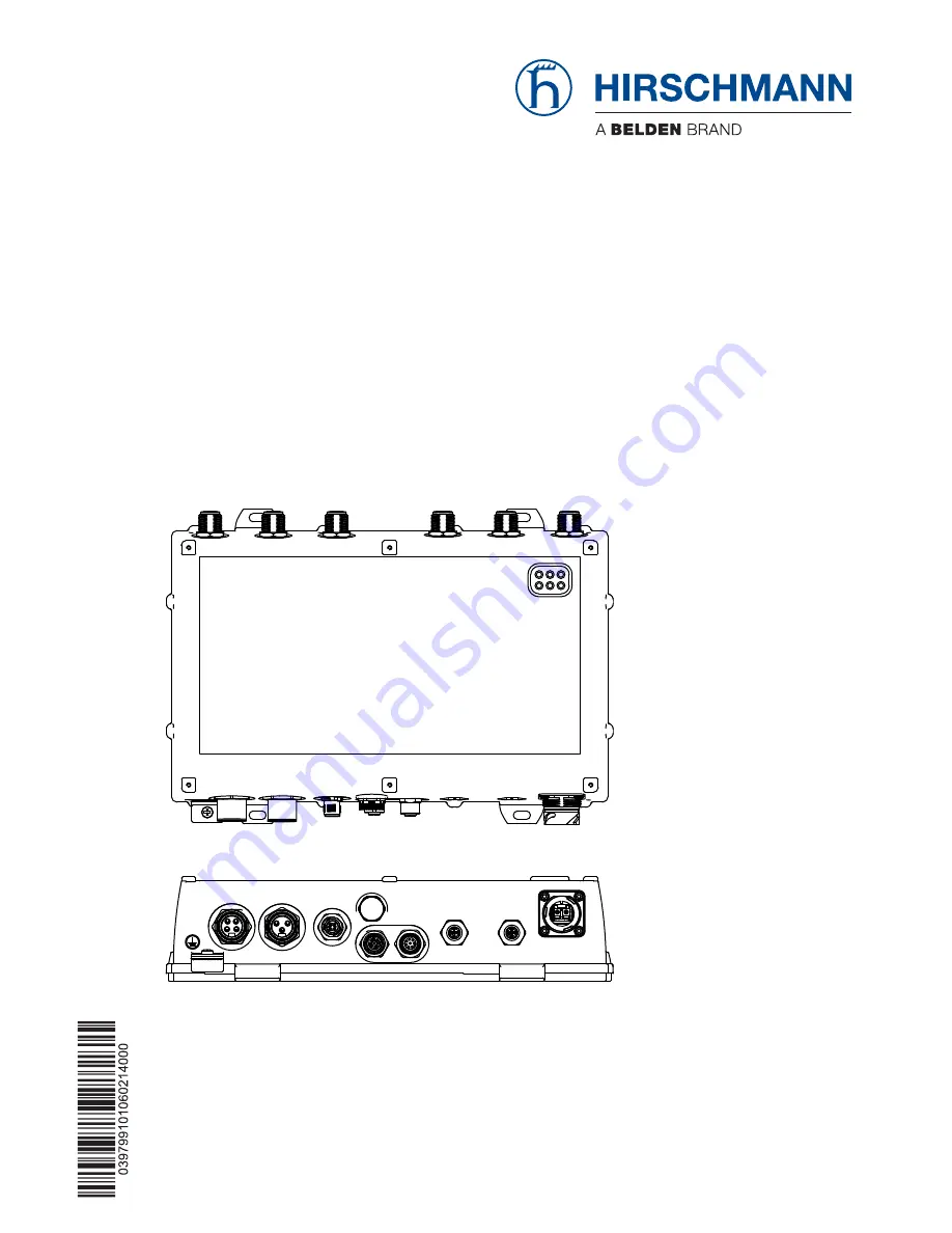
Страница 22: ...module 1 For device variants with 1 WLAN module Not present 2 alternatively depending on device variant For device variants with 2 WLAN modules 3 N socket for WLAN module 2 For device variants with 1...
Страница 23: ...p Installation characteristic value A and B The reset button below a screwable IP67 protective cap 9 Solely for device variants featuring working voltage with the characteristic value C K or W 4 pin A...
Страница 24: ...value C on page 39 1 5 2 Working voltage with the characteristic value K A 3 pin 7 8 connector is available to supply the device You will find further information under Working voltage with the charac...
Страница 25: ...rs or twisted pairs to a combo port Note Plug a connector or SFP module that you want to use for the data transmission only into the socket of the combo port 10 100 1000 Mbit s PoE PD port Note To con...
Страница 26: ...0 Mbit s PoE PD port 8 pin X coded M12 plug phantom voltage Pin Signal Function PoE PD voltage 1 MDX1 Receive path 2 MDX1 Receive path 3 MDX0 Transmission path 4 MDX0 Transmission path 5 MDX2 x pin 6...
Страница 27: ...ousing Pin Signal 10BASE T 100BASE TX 1000BASE T 1 MDX1 Receive path BI_DB 2 MDX1 Receive path BI_DB 3 MDX0 Transmission path BI_DA 4 MDX0 Transmission path BI_DA 5 MDX2 BI_DC 6 MDX2 BI_DC 7 MDX3 BI_D...
Страница 28: ...as that pertain to your application case The Hirschmann BAT Planner provides support in selecting suitable antennas You obtain the BAT planner free of charge under www hirschmann com The Antenna Guide...
Страница 29: ...off for a brief time and then lights up for considerably longer about 10x as long in the specified color Flickering means that the LED switches on and off at irregular intervals Running light means t...
Страница 30: ...formed by P1 red green flashing quickly Unprotected configuration as no password or the default password is set a red off flashing quickly Hardware error detected b red green Running light of P1 and P...
Страница 31: ...configuration of a point to point WLAN line by connecting two devices directly via the serial interface You will find more information here User Manual Configuration and Administration Guide See tabl...
Страница 32: ...the software The ACA21 M12 interface is designed as a 5 pin A coded M12 plug with shielding Pins of the M12 socket on the device Pin assignment for the connection with a cable Pins of the DB9 plug on...
Страница 33: ...find further information under Signal contact on page 41 1 11 Operation element reset button The device has a reset button Note The reset button is located behind a screwable IP67 pressure equalizatio...
Страница 34: ...ion class IP65 67 under the following conditions exclusively All the connectors and cables connected also fulfill protection class IP65 67 The locking screws seal all unused connections and ports The...
Страница 35: ...mm The head diameter is maximum 0 47 in 12 mm The diameter of a possibly used washer is maximum 0 47 in 12 mm Prepare the assembly at the installation site See Dimension drawings on page 54 Install t...
Страница 36: ...ng set The pole mounting set you obtain as an accessory See Accessories on page 68 The clamp diameter of the mast clamp included in the pole mounting set is maximum 2 56 in 65 mm For larger pole diame...
Страница 37: ...an SFP transceiver first remove the protective cap from the SFP transceiver Push the SFP transceiver with the lock closed into the socket Note For this device only use suitable SFP modules from Hirsch...
Страница 38: ...the terminators supplied into the unused sockets to avoid radio signals from one WLAN module being received by the other WLAN module Relevant for use of BAT ANT N MiMo 18N IP65 with FCC and approval...
Страница 39: ...ltage inputs are uncoupled 2 6 1 Working voltage with the characteristic value C For every working voltage to be connected perform the following steps Type and specification of the working voltage Pin...
Страница 40: ...nces 48 V 320 V 2 Plus terminal of the working voltage 3 Minus terminal of the working voltage AC voltage Rated voltage range AC 110 V 230 V 50 Hz 60 Hz 1 Protective conductor Voltage range AC incl ma...
Страница 41: ...age DC 24 V 1 Minus terminal of the working voltage Voltage range DC incl maximum tolerances 18 V 32 V 2 3 4 Plus terminal of the working voltage Table 16 Working voltage with the characteristic value...
Страница 42: ...pair cable Power over Ethernet you start the operation of the device 2 7 1 Connecting the power supply through a 7 8 connector Plug the socket into the 7 8 connector on the device Enable the working v...
Страница 43: ...ta lines according to your requirements 1000 Mbit s F O port You will find further information under 1000 Mbit s F O port on page 28 Note Make sure that you connect LH ports exclusively with LH ports...
Страница 44: ...ng documentation on the supplied CD DVD User Manual Configuration and Administration Guide User Manual Operation and Maintenance Guide 3 2 Configuring antennas Note When installing antennas observe th...
Страница 45: ...fig to start the configuration of the device This software is located on the CD DVD provided Go to the settings for Wireless LAN Enter the country in which you are installing the device see the follow...
Страница 46: ...stallation BAT F Release 06 02 2014 Subtract the cable attenuation and any losses due to over voltage protector installed devices from the antenna gain and enter the result in dB in the antenna gain f...
Страница 47: ...button for maximum 4 seconds or 11 to 15 seconds 4 2 Resetting the configuration hard reset The hard reset is used to reset the device to the factory settings You require this function for example if...
Страница 48: ...se 06 02 2014 4 3 Loading the configuration To load a configuration saved on the device press the reset button for at least 16 seconds If the device does not provide a saved configuration the device r...
Страница 49: ...the frequency of the switching operations Check the resistance of the closed relay contacts and the switching function depending on the frequency of the switching operations Hirschmann continually wo...
Страница 50: ...Disable the working voltage Pull off the power supply lines and signal lines Remove the antennas Disconnect the grounding WARNING ELECTRIC SHOCK Disconnect the grounding solely after disconnecting all...
Страница 51: ...unting tool 1 mounting side 2 barbed hooks 3 disassembly side Insert the SFP mounting tool so into the SFP transceiver that the barbed hooks point to the locking handle of the SFP transceivers Gently...
Страница 52: ...pin 7 8 connector Power failure bypass 10 ms at 20 4 V DC Overload current protection at input Non replaceable fuse Back up fuse Nominal rating Characteristic Max 6 3 A slow blow Working voltage with...
Страница 53: ...8 F 40 C 70 C b Humidity 10 95 Air pressure Up to 2000 m 795 hPa higher altitudes on request maximum 1060 hPa 1312 ft 400 m Climatic conditions during storage Ambient air temperaturec 40 F 185 F 40 C...
Страница 54: ...sion drawings Figure 4 Dimensions of device variants and distance between suspensions Figure 5 Dimensions of the device variants with impact protection 73 184 311 207 2 19 mm in 12 24 7 24 8 15 8 62 2...
Страница 55: ...Installation BAT F Release 06 02 2014 55 Figure 6 Distances of the suspension with impact protection 184 207 38 69 mm inch 7 24 1 52 8 15...
Страница 56: ...authentication for faster roaming with IEEE 802 1x a With encryptions type TKIP and WEP the device falls back on IEEE 802 11b g or IEEE 802 11a depending on frequency b With encryptions type TKIP and...
Страница 57: ...2 Mbps 16 dBm 93 dBm 18 Mbps 16 dBm 91 dBm 24 Mbps 16 dBm 88 dBm 36 Mbps 15 dBm 84 dBm 48 Mbps 13 dBm 80 dBm 54 Mbps 12 dBm 79 dBm Table 18 Receive sensitivity transmission power and data rate accordi...
Страница 58: ...73 dBm MCS15 15 dBm 72 dBm MCS16 23 dBm 87 dBm MCS17 23 dBm 90 dBm MCS18 23 dBm 86 dBm MCS19 23 dBm 82 dBm MCS20 16 dBm 79 dBm MCS21 17 dBm 75 dBm MCS22 17 dBm 73 dBm MCS23 16 dBm 72 dBm Table 21 Rec...
Страница 59: ...MCS13 15 dBm 77 dBm MCS14 15 dBm 75 dBm MCS15 14 dBm 73 dBm MCS16 21 dBm 92 dBm MCS17 21 dBm 91 dBm MCS18 21 dBm 89 dBm MCS19 21 dBm 84 dBm MCS20 16 dBm 81 dBm MCS21 15 dBm 77 dBm MCS22 14 dBm 75 dBm...
Страница 60: ...pical receive sensitivity 06Mbps 10 dBm 93 dBm 09Mbps 10 dBm 93 dBm 12Mbps 10 dBm 93 dBm 18Mbps 10 dBm 91 dBm 24Mbps 10 dBm 88 dBm 36Mbps 9 dBm 84 dBm 48Mbps 7 dBm 80 dBm 54Mbps 6 dBm 79 dBm Table 23...
Страница 61: ...86 dBm MCS11 21 dBm 82 dBm MCS12 16 dBm 79 dBm MCS13 16 dBm 75 dBm MCS14 15 dBm 73 dBm MCS15 15 dBm 72 dBm MCS16 23 dBm 87 dBm MCS17 23 dBm 90 dBm MCS18 23 dBm 86 dBm MCS19 23 dBm 82 dBm MCS20 16 dBm...
Страница 62: ...dBm 73 dBm MCS8 7 dBm 92 dBm MCS9 7 dBm 91 dBm MCS10 6 dBm 89 dBm MCS11 7 dBm 84 dBm MCS12 5 dBm 81 dBm MCS13 2 dBm 77 dBm MCS14 2 dBm 75 dBm MCS15 1 dBm 73 dBm MCS16 8 dBm 92 dBm MCS17 8 dBm 91 dBm...
Страница 63: ...61000 4 5 Voltage surges DC power line 2 kV line ground 1 kV line line AC Power Line 4 kV line ground 2 kV line line Data line shielded 4 kV line ground Data line unshielded 2 kV line ground Data lin...
Страница 64: ...Electromagnetic compatibility for radio equipment and services EN 301 489 17 Electromagnetic compatibility EMC for radio equipment and services specific conditions for 2 4 GHz broadband transmission s...
Страница 65: ...km LX LC MM 1310 nmc c With F O adapter compliant with IEEE 802 3 2002 clause 38 single mode fiber offset launch mode conditioning patch cord 50 125 m 0 10 5 dB 0 550 m 1 0 dB km 800 MHz km LX LC MM...
Страница 66: ...connection 2 Power supply plug for cable diameters of 0 24 to 0 32 in 6 to 8 mm model dependent on the characteristic value of the socket You find a power supply plug with a larger thread e g for cab...
Страница 67: ...the characteristic value of the socket You find a power supply plug with a larger thread e g for cable diameters of 0 32 to 0 39 in 8 to 10 mm in the table Other accessories See Accessories on page 68...
Страница 68: ...le on the enclosed CD DVD or as a download on the Hirschmann product pages www hirschmann com Note IP67 V1 connector housings according to IEC 61076 3 106 Variant 1 you will receive from BTR NETCOM Gm...
Страница 69: ...n 8 to 8 mm Available at Lumberg Automation 11216 Terminal cable M12 connector 8 pin on DB9 socket 942 087 001 Locking screw for M12 socket metal IP67 25 pieces 942 057 001 Locking screw for M12 plug...
Страница 70: ...vehicles Part 2 Requirements for fire behaviour of materials and components EN 50155 Railway applications Electronic equipment used on rolling stock EN 55022 Information technology equipment Radio di...
Страница 71: ...mail inet ap belden com Hirschmann Competence Center The Hirschmann Competence Center is ahead of its competitors Consulting incorporates comprehensive technical advice from system evaluation through...
Страница 72: ......