


77
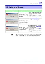
7.2 Allocation to Output Channels
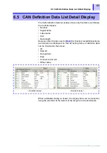
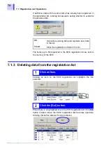
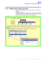
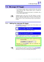
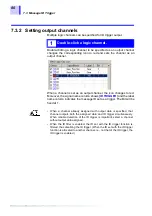
7.2.3 Setting logic output channels
Logic output channels are set the same way as for analog output
channels.
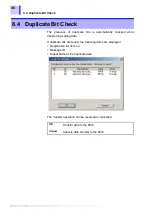
❖
When assigned data is 2 bits or larger, the data is automatically
allocated so that the most significant bit is assigned to the channel
selected, with the rest allocated to the following channel.
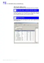
Example 1
: Data with label name [
abc
] and a data length of 5 bits assigned to Bit 1 in Ch A
is allocated as shown below.
In this example, if another signal is already allocated to 3 bits from Bit 2 to Bit 0 in Ch B, the
original signal only remains in Bit 0 in Ch B because overlapping bits are overwritten in one
bit units.
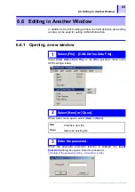
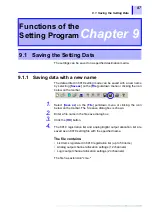
Example 2
: Dragging and dropping data with a data length of 3 bits to Bit 3 in Ch A.
3
CH A
2
1 0 3 2 1 0
CH B
CH C
1 0 3 2
3 2 1 0
4
A1 abc bit4
A0 abc bit3
B3 abc bit2
B2 abc bit1
B1 abc bit0
Содержание 8910
Страница 1: ...8910 Instruction Manual CAN ADAPTER EN Aug 2018 Revised edition 7 8910A981 07 18 08H ...
Страница 2: ......
Страница 8: ...Contents vi ...
Страница 18: ...Notes on Use 10 ...
Страница 44: ...3 5 Operation Map 36 ...
Страница 48: ...4 2 Program Setup 40 ...
Страница 56: ...5 4 Operation Flowchart 48 ...
Страница 78: ...6 6 Editing in Another Window 70 ...
Страница 90: ...7 4 Setting the ID Filter 82 ...
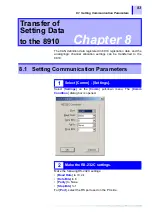
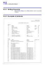
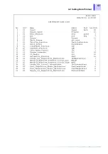
Страница 99: ...91 9 2 Setting Data Printout ...
Страница 130: ...10 2 Using the 8910 with the 8841 8842 MEMORY HiCORDER 122 ...
Страница 147: ......
Страница 148: ......
Страница 149: ......
Страница 150: ......