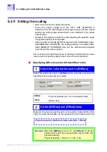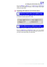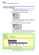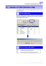
5.4 Operation Flowchart
46
5.4 Operation Flowchart
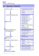
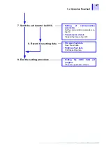
1. Prepare for setting.
2. Set the CAN definition data.
• Connecting the PC to the 8910
Connect the PC to the 8910 via the
RS-232C.
• Starting up the 8910 CAN set
program
• Setting the message ID
Set the message ID.
• Setting the data length
Set the data size.
• Setting the data start position
Set the data location.
• Setting the data pattern
Set the data pattern
(byte arrangement).
• Setting the sign
Set whether the data has a sign.
• Setting the signal name/label
name
Set the name of the data.
• Setting the scaling
Set the physical quantity of data.
3. Register the definition data
in the registration list.
4. Set the ID filter.
• Loading CAN definition data
Read the data from the file.
• Registration of definition data in
the registration list
Select the data from the definition list
and register it.
• Setting the ID filter
Set the filter ON/OFF for each input
port.
5. Assign data to output channels.
• Allocation of data to analog
channels
Set the output analog channels.
• Allocation of data to logic
channels
Set the output logic channels.
<Go to the next page>
• Selection of a message ID
Select an applicable message ID.
• Selection of output channels
Select a pulse output channel.
6. Set the ID trigger.
Содержание 8910
Страница 1: ...8910 Instruction Manual CAN ADAPTER EN Aug 2018 Revised edition 7 8910A981 07 18 08H ...
Страница 2: ......
Страница 8: ...Contents vi ...
Страница 18: ...Notes on Use 10 ...
Страница 44: ...3 5 Operation Map 36 ...
Страница 48: ...4 2 Program Setup 40 ...
Страница 56: ...5 4 Operation Flowchart 48 ...
Страница 78: ...6 6 Editing in Another Window 70 ...
Страница 90: ...7 4 Setting the ID Filter 82 ...
Страница 99: ...91 9 2 Setting Data Printout ...
Страница 130: ...10 2 Using the 8910 with the 8841 8842 MEMORY HiCORDER 122 ...
Страница 147: ......
Страница 148: ......
Страница 149: ......
Страница 150: ......

