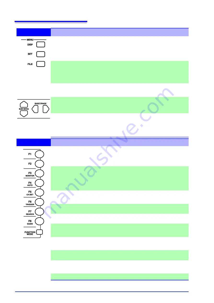
2.1 Operating Keys
14
2
MENU (Screen Select)
DISP key
Displays the Waveform screen showing recorded data.
(Setting choices can also be changed from the Waveform screen)
See
When using A/B cursors or calculation functions, waveforms and
numerical values can be displayed on the same screen.
See
SET key
Displays the Settings screens, where you can change various settings
such as measurement configuration and trigger criteria.
See
Hold this key to display the System screen.
See
FILE key
Displays the File screen where you can load settings and measure-
ment data, and manage files.
See
SUB MENU keys
Selects among setting items on the Waveform screen, or among the
Settings menu items on the Settings or System screen.
(Which Settings menu items are available depends on the currently
enabled operating function)
SHEET/PAGE
keys
Switches the sheet displayed on the Waveform screen.
When using the Memory Division function, each block can be
switched on the Waveform screen.
See
"13.2.6 Specifying SHEET/PAGE Key Operations" (p. 357)
Switches the page displayed on the Settings screen.
Switches between the folder tree and file list on the File screen.
3
F keys (Select setting contents or function)
F1 to F8 keys
These keys correspond to the setting choices displayed in the GUI
area at the right side of the screen (GUI = Graphical User Interface).
Press a key to select its corresponding choice.
“F keys” indicates all of the
F1
to
F8
keys collectively.
See
"3.3.2 To Change a Setting" (p. 63)
FUNCTION MODE
key
Alters the functional mode of the
F1
to
F8
keys.
Available functions depend on the type of display screen.
[SET]
(selection choice at screen cursor location)
[FN]
(function
displayed for F1 to F8)
[MACRO]
(simple operations)
See
Waveform Screen: "Function Modes and Settings" (p. 26),
File Screen: "Function Modes and Settings" (p. 43)
(*F1)
Displays information such as the measurement values and numerical
calculation results.
See
"8.4 Displaying Measured Values and Information" (p. 196)
(*F2)
Displays a gauge at the left side of the screen.
See
"8.5 Applying Gauges" (p. 198)
MONITOR (*F3)
Displays input levels for monitoring.
See
"8.6 Monitoring Input Levels (Level Monitor)" (p. 199)
AUTO
(*F4)
Automatically sets the timebase and voltage axis range for the input
waveform (Auto-Ranging Function).
See
"3.3.5 Automatic Range Setting (Auto-Ranging Function)" (p. 74)
CH.SET
(*F5)
Displays the CH ALL SET dialog.
Channel settings can be verified and changed.
See
"5.7 Setting Input Channels from the Waveform Screen" (p. 134)
TRIGGER
(*F6)
Applies an unconditional (manual) trigger.
See
"6.10 Triggering Manually (Manual Trigger)" (p. 165)
SEARCH
(*F7)
Displays the SEARCH dialog. Any desired waveform can be
searched.
See
"8.14 Searching a Waveform" (p. 222)
GUIDE
(*F8)
(Support planned in later version upgrade)
(*F1) to (*F8):
From the Waveform
screen, press the FUNC-
TION MODE key to
change to the FN mode,
then press one of the F1
to F8 keys. To revert to
the original functions,
press the FUNCTION
MODE key again.
Содержание 8860-50
Страница 2: ......
Страница 12: ...Contents x...
Страница 18: ...Reading this Manual 6...
Страница 24: ...1 3 Interconnection and Block Diagrams 12...
Страница 180: ...6 12 Making Trigger Settings on the Waveform Screen 168...
Страница 246: ...8 15 Inserting and Searching for Event Marks on a Waveform 234...
Страница 354: ...12 7 Print Examples 342 Print Example 4 Row Printing 1 4 steps Settings data Each step is 25 div...
Страница 356: ...12 7 Print Examples 344 A B Waveform_________________________________________________...
Страница 360: ...12 7 Print Examples 348 Event ________________________________________________________ Event mark...
Страница 406: ...14 2 External I O 394...
Страница 489: ......
Страница 490: ......


