background image

HYBRID/TROUBLE SHOOTING

3–136

DTC: P0A1D (TC17)

EN01H03ZZZ030602003020

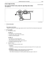
DTC: P0A1D (TC17) Abnormality in HV ECU function

INFORMATION

1.

Technical description

<Description of malfunction>

Detected an abnormality in the CAN communication circuit in the HV ECU. (DIAG CAN register stuck)

2.

DTC set condition

(1)

DTC detection condition

The starter key is set to the ON position.

HV ECU runs within 0.5 second.

(2)

Judgement criteria

When an abnormality occurs in reading or writing of the DIAG CAN controller ID/message register

3.

Reset condition

When reading and writing of the DIAG CAN controller ID/message register are normally executed

4.

Indication, warning or system control regulation when the DTC is set.

MIL: ON

HV warning light: ON

5.

Symptoms on the vehicle when the DTC is set

<Symptoms on the vehicle due to backup control (fail safe)>

<Symptoms on the vehicle due to malfunction>

The idling stop function becomes inoperative.

The regeneration function stops, which may reduce the feeling of deceleration during deceleration.

The CHG, AST, ECO, and SOC lamp may go off.

6.

Pre-inspection work

Check the battery voltage to make sure that there is no abnormality.

7.

After-inspection work

Clear the recorded DTC.

Check that no DTC is detected after test-driving the vehicle.

8.

Estimated failure factors

Malfunction of HV ECU

Содержание 195h Series

Страница 1: ... in this manual are based upon the latest product information available at the time of printing Hino Motors Sales U S A Inc reserves the right to make changes at any time without prior notice Please note that the publications below have also been prepared as relevant workshop manuals for the components and sys tems in these vehicles Manual Name Pub No Chassis Workshop Manual S1 LXJE03A S1 LXJE03A ...

Страница 2: ...e this chart to the appropriate chapter numbers for servicing your particular vehicle CHAPTER MANUAL No S7 LXJE03C 4 7 U S A S7 LXJE04C 4 7 CANADA MODELS HINO 155 155h 195 195h Production Code XFC710 XFC720 XFC740 XJC700 XJC710 XJC720 XJC740 HYBRID 3 001 ...

Страница 3: ...SUSPENSION BODY CONSTRUCTION INDEX TROUBLE SHOOTING GROUP 1 2 SUSPENSION WORKSHOP MANUAL All rights reserved This manual may not be reproduced or copied in whole in part with out the written consent of Hino Motors Ltd BODY INSIDE ACCESSORY BODY OUTSIDE ACCESSORY AIR BAG AND SEAT BELT HEATER AND AIR CONDITIONER GENERAL INTRODUCTION ...

Страница 4: ...CONTROL SYSTEM INDEX TROUBLE SHOOTING GROUP 2 2 ELECTRICAL ...

Страница 5: ...C6B 3 217 DTC P0BCA TC68 3 221 DTC P0C73 TC80 3 227 DTC P3000 TC42 3 234 DTC P3001 TC41 3 243 DTC P3001 TC43 3 246 DTC P3001 TC44 3 249 DTC P3001 TC45 3 252 DTC P3001 TC46 3 255 DTC P3001 TC47 3 259 DTC P3001 TC4A 3 263 DTC P3001 TC4B 3 267 DTC P3001 TC4C 3 270 DTC P3009 TC49 3 273 DTC P3128 TC7D 3 289 DTC P3129 TC7C 3 301 DTC P314C TC82 3 306 DTC P314D TC81 3 311 DTC P324B TC62 3 323 DTC P324C TC...

Страница 6: ...22 3 732 DTC P0AEE TC23 3 735 DTC P0AEF TC24 3 738 DTC P0AF0 TC25 3 742 DTC P0BEA TCB3 3 746 DTC P0BEA TCB4 3 749 DTC P0BEB TC9A 3 752 DTC P0BEC TC9B 3 755 DTC P0BEE TCB5 3 758 DTC P0BEE TCB6 3 761 DTC P0BEF TC9C 3 764 DTC P0BF0 TC9D 3 767 DTC P3126 TC12 3 770 DTC U0073 TC91 3 783 DTC U0074 TC3E 3 788 DTC U0293 TC31 3 792 BATTERY ECU 3 801 DIAGNOSIS CODE TABLE 3 801 LIST OF FREEZE FRAME DATA 3 804...

Страница 7: ...P3014 3 1054 DTC P3015 3 1059 DTC P3016 3 1064 DTC P3017 3 1069 DTC P3018 3 1074 DTC P3019 3 1079 DTC P301B 3 1084 DTC P3020 3 1087 DTC P3021 3 1092 DTC P3022 3 1097 DTC P3023 3 1102 DTC P3024 3 1107 DTC P3025 3 1112 DTC P3026 3 1117 DTC P3027 3 1122 DTC P3028 3 1127 DTC P3029 3 1132 DTC P302F 3 1137 DTC P3065 3 1142 DTC P308A 3 1147 DTC U0074 3 1152 DTC U0293 3 1156 ...

Страница 8: ...WARNING LIGHT ENGINE ECU VEHICLE CONTROL ECU CLUTCH ECU MIL HV ECU OR COMMUNICATION FUNCTION PERFORM ALARMING ONLY WHEN THE FUNCTION FAILS INVERTER MALFUNCTION INFORMATION MIL ON REQUEST MALFUNCTION INFORMATION MIL ON REQUEST MALFUNCTION INFORMATION MIL ON REQUEST MIL ON REQUEST HV ECU READ CODE AND DIAGNOSE READ CODE AND DIAGNOSE READ CODE AND DIAGNOSE SERVICE TOOL HYBRID CONTROL SYSTEM CAN SIGNA...

Страница 9: ...urn on or turn off MIL 2 When a malfunction relevant to emission occurs in the HV system or vehicle control ECU the MIL light ON request is sent from the HV ECU to the engine ECU using CAN 3 HV battery ECU inverter and vehicle control ECU send the MIL light ON request to the engine ECU using CAN via HV ECU LIGHT ON OR LIGHT OFF HV WARNING LIGHT HV ECU MALFUNCTION INFORMATION HV BATTERY ECU INVERTE...

Страница 10: ...function is recovered control is switched from failsafe control to normal control however the Confirmed diagnosis code is not deleted Code name Definition of diagnosis code HV warning light MIL Effect on vehicle Pending diagnosis code Diagnosis code that is being detected malfunc tion is not confirmed Light OFF Light OFF Normal control Confirmed diagnosis code Diagnosis code in which the malfuncti...

Страница 11: ...ction in 1DCY 1 For the malfunction in which the Confirmed malfunction is confirmed in DCY the Pending malfunction is not confirmed COMPLETION OF DCY 1 COMPLETION OF DCY 2 DETECTION OF MALFUNCTION CONFIRMATION DETECTION OF MALFUNCTION CONFIRMATION LIGHT ON LIGHT ON DCY VEHICLE CONDITION PENDING MALFUNCTION CONFIRMED MALFUNCTION HV WARNING LIGHT MIL SHTS03ZZZ0300005 CONFIRMATION LIGHT ON LIGHT ON C...

Страница 12: ...condition is not satisfied in 1DCY Instant deletion Confirmed diagnosis code None Instant deletion Permanent diagnosis code This code is deleted when condition to be judged normal is satisfied in 3DCY 1 This code is deleted after performing the predetermined operation when condition to be judged normal is sat isfied and malfunction detection con dition is not satisfied in 1DCY after deleting the d...

Страница 13: ...ETION OF DCY 5 DETECTION OF MALFUNCTION DETECTION OF MALFUNCTION DCY VEHICLE CONDITION PENDING MALFUNCTION CONFIRMED MALFUNCTION PERMANENT MALFUNCTION HV WARNING LIGHT MIL NORMAL JUDGMENT 1 NORMAL JUDGMENT 2 NORMAL JUDGMENT 3 NORMAL JUDGMENT DCY 1 NORMAL JUDGMENT DCY 2 NORMAL JUDGMENT DCY 3 SHTS03ZZZ0300008 CONFIRMATION DELETION DELETION DELETION DELETION OF THE MALFUNCTION CODE USING THE SERVICE ...

Страница 14: ...ff when the diagnosis code is deleted at b When the HV warning light turns off it is possible to check that there is no malfunction in the HV system Condition to be judged normal for the malfunction occurred in the above steps d to g must be satisfied Condition to be judged normal varies depending on malfunction 2 Procedure for deleting the Permanent diagnosis code in 3DCY a Turn the starter key O...

Страница 15: ...ary noise due to partial fitting of the connector if parts are returned to normal without repairing or replacing parts using the diagnostic chart The service tool or trouble shooting tool described in the trouble shooting chart indicates the genuine Hino ser vice tool If the starter key is turned ON in the state that connectors etc are disconnected while performing the trouble shooting chart the m...

Страница 16: ...d high voltage circuit is acti vated when the starter key is turned to ON CAUTION Since any failure may occur when the starter key is turned to ON with the service plug removed never turn the starter key to ON unless otherwise instructed in this document 2 All wire harness connectors for the high voltage circuit are orange colored Further HIGH VOLTAGE caution label is attached to high voltage comp...

Страница 17: ...condition of high voltage terminals and connector conditions again before connecting the service plug 9 Do not reserve the hybrid battery 10 Do not disassemble the hybrid battery CAUTION High voltage is applied to the hybrid battery even when the ser vice plug is disconnected Further high alkaline electrolyte is used 11 Make sure to use the insulated tools Recommended tools FACON s Facom quality i...

Страница 18: ...HYBRID TROUBLE SHOOTING 3 14 SHTS03ZZZ0300012 ...

Страница 19: ...4 8 11 12 13 14 15 16 17 18 19 2 3 4 5 6 7 8 9 20 24 23 25 26 27 28 29 21 22 30 1 10 1 2 3 4 1 2 3 4 5 6 7 8 9 10 11 30 31 12131415 1617181920 2122232425 26272829 3233343536 37383940 7 8 9 10 1112 3 4 13 14 15 16 17 18 19 20 21 22 23 24 1 2 5 6 1819 20 21 22 23 24 25 26 7 8 9 1011121314151617 1 2 3 4 5 6 BATTERY ECU CAN A B F G J C DIAG CAN INVERTER COOLING WATER PUMP BATTERY ECU TEMPERATURE MONIT...

Страница 20: ...1 2 3 4 GRAY BLACK WHITE RELAY BLOCK SIDE BLACK BLACK BLACK BLACK WHITE WHITE BLACK BLACK 1 2 3 4 5 6 7 8 9 10 11 12 13 14 15 16 4 3 2 1 8 7 6 5 12 11 10 9 16 15 14 13 RELAY BLOCK SIDE COMPONENT SIDE COMPONENT SIDE 3 5 L N 2 1 3 5 2 1 1 2 INVERTER START RELAY L N HV BATTERY START RELAY O J C CTRL CAN P PCU HARNESS 16 PIN R HV BATTERY COOLING FAN S SMR DRIVE SERVICE PLUG SWITCH T X PCU HARNESS 24 P...

Страница 21: ... BATT OUT F BATT IN D BATT OUT I J H G 10 12 13 14 15 16 17 18 19 20 2 3 4 5 6 7 8 9 21 24 11 23 25 26 27 28 29 22 30 1 1 21 2 22 3 23 4 24 5 25 6 26 7 27 8 28 9 29 30 10 31 11 32 12 33 13 34 14 35 15 36 16 37 17 38 18 39 19 40 20 METER 1 d 1 A RESOLVER B ROTATION MACHINE TEMPERATURE SENSOR C D E F G H HIGH VOLTAGE J B IN BATTERY PACK INVERTER HIGH VOLTAGE I J SERVICE PLUG a STARTER SWITCH b AT EC...

Страница 22: ... 15 36 16 37 17 38 18 39 19 40 20 5 1 3 2 4 6 7 8 9 1314 24 151617181920 212223 25262728293031323334 16 15 14 13 12 11 10 9 8 7 6 5 4 3 2 1 h BATT m BATT p INV 3 1 2 5 q INV k DDC I DDC 101112 e f ABS ECU CLUTCH ECU k l m n p q HIGH VOLTAGE J B IN ECU BOX r IG1 1 RELAY t NEUTRAL SWITCH h DLC3 1 10 5 4 3 2 8 9 6 7 SHTS03ZZZ0300016 ...

Страница 23: ...VICE PLUG 288V HV BATTERY CURRENT SENSOR GND L 1 L L x PCI_B_2 20A PCI_B_20A x L 3 n p J B l 2 5 WATER PUMP RADIATOR FAN HV BATTERY START RELAY F F E F F E E 4 1 3 3 2 R R P P R 3 A 1 A 2 A 13 A 18 A 19 A 12 9 P 13 P 14 4 1 2 1 11 R P 2 12 P 15 P 6 P 7 P 2 3 4 5 1 P 16 N 1 N x N N 3 1 2 3 2 5 1 2 3 4 5 6 7 8 9 12 11 10 14 13 15 16 18 19 20 21 22 23 24 25 m q J B k P P P P HV BATTERY COOLING FAN KE...

Страница 24: ... 24 D 12 D 14 D 13 D 15 D 27 D 3 Y 8 Y 4 Y ROTATION MACHINE THERMISTER ROTATION MACHINE 16 X W1 V1 U1 CN4 40 CON3 CN4 39 CON2 CN3 38 CON1 CN4 16 ILK1 CN4 5 ILKO INVERTER PCU INTERNAL CIRCUIT HV ECU CAN J C CONTROL CAN J C DIAG c c ABS ECU 20 H 29 Y 1 R2 Y 2 S1 Y 5 S2 Y 6 RESOLVER S3 Y 10 S4 F F GND B ON Y 11 SLD3 Y 9 19 J 21 J 22 J G h h h h h DLC3 15 5 6 3 4 7 8 1 2 f f X x x x X CLUTCH ECU 13 23...

Страница 25: ... week month Running condition Road surface state When starting During acceleration During steady running During deceleration During braking During stoppage During parking During turning During ABS operation Others Vehicle speed km h Shift position display Lighting of warning light Brake operation Frequency of occurrence A C status 1 2 3 4 5 at operation 6 R Engine status Flat horizonal road Upward...

Страница 26: ...ty in power supply voltage 71 Control power supply voltage reduction HV system stop Since the hybrid system stops the following symp tom occur The engine may not start running However the engine starts up by the starter for starter equipped vehicles Idling stop is not working Lowering the speed during deceleration may decrease to deactivate the regenera tion function 1 P060B Abnormality in A D con...

Страница 27: ... HV water pump drive signal Low abnormal ity 7F Disconnection or GND short circuit of the HV water pump drive signal cir cuit Behavior of vehicle does not vary 1 P0A07 HV water pump drive signal High abnormal ity 7E HV water pump drive signal cir cuit power sup ply positive side shorted Behavior of vehicle does not vary 1 P0A0F Engine system abnormality 31 Engine misfire The engine does not start ...

Страница 28: ...eed during deceleration may decrease to deactivate the regenera tion function 1 P0A7E Abnormality in high tempera ture of HV bat tery 48 Abnormally high tempera ture of the HV battery Idling stop is not working Lowering the speed during deceleration may decrease to deactivate the regenera tion function 1 P0A82 Abnormality in function of HV battery cooling fan 67 Abnormality in the HV battery cooli...

Страница 29: ...ality in HV battery cooling fan revolving num ber signal High 68 HV battery cooling fan speed signal circuit power supply positive side shorted Behavior of vehicle does not vary 1 P0C73 Abnormality in HV water pump function 80 Abnormality in the HV water pump function Behavior of vehicle does not vary 2 P3000 Abnormality in status of HV battery ECU IG signal 42 Abnormality in the HV battery ECU IG...

Страница 30: ...ine starts up by the starter for starter equipped vehicles Idling stop is not working Lowering the speed during deceleration may decrease to deactivate the regenera tion function 1 P3001 Abnormality in HV battery line 46 Request for stopping dis charge of the HV battery The engine may not start running However the engine starts up by the starter for starter equipped vehicles Idling stop is not wor...

Страница 31: ...for stopping charge The engine may not start running However the engine starts up by the starter for starter equipped vehicles Idling stop is not working Lowering the speed during deceleration may decrease to deactivate the regenera tion function 1 P3009 Abnormality in leakage 49 Electrical leak age Behavior of vehicle does not vary 1 P3128 Abnormality in HV radiator fan revolution num ber Low 7D ...

Страница 32: ...ay Low 64 GND short cir cuit of the HV battery ECU start relay exci tation circuit Idling stop is not working Lowering the speed during deceleration may decrease to deactivate the regenera tion function 1 P33B2 Abnormality in HV battery ECU start relay High 63 The HV battery ECU start relay excitation cir cuit discon nected or power supply positive side shorted Idling stop is not working Lowering ...

Страница 33: ...V battery ECU CAN communi cation blackout Idling stop is not working Lowering the speed during deceleration may decrease to deactivate the regenera tion function 1 U0121 ABS ECU CAN communica tion blackout 24 ABS ECU CAN communica tion blackout Idling stop is not working 1 U0155 Meter ECU CAN communica tion blackout 25 Meter ECU CAN communica tion blackout Idling stop is not working 1 U110A Vehicl...

Страница 34: ... request mode Represents the operation request to the engine 0 No request 1 Rotational request 2 Rota tional restriction 3 Torque limiting Torque instruction 4 0 4 Required engine torque limiting value Ratio of limiting request torque to the engine to standard engine torque 128 127 Specified value of motor torque Represents a torque command value to the inverter 32 768 32 767 Nm Effective motor to...

Страница 35: ...st brake switch CAN reception Represents the retarder lever signal input status ON 1 OFF 0 0 1 HV control mode information Represents the operating condition of the HV system 0 OFF 1 Engine startup 2 At acceleration by motor 3 Deceleration by motor retarder 4 Deceleration by motor or foot brake 5 Battery charging 6 Engine stop 7 Forced battery charging 8 At manufacturing inspection 9 At EV 10 At g...

Страница 36: ...ooling FAN drive request Duty HV battery cooling FAN drive request Duty 0 100 HV battery cooling FAN drive request revolution HV battery cooling FAN drive request revolution 0 10 000 r min HV battery cooling FAN revolu tion HV battery cooling FAN revolution HINT Even if the HV battery cooling FAN drive request revolution is 0 r min 0 100 r min appears 0 10 000 r min HV battery cooling FAN revolu t...

Страница 37: ... HV battery current Represents the HV battery DC current 500 500 A Power supply voltage Represents the HV ECU power supply voltage 0 40 V HV battery capacity SOC Represents the HV battery capacity SOC 0 100 Maximum temperature of the HV battery Represents the maximum temperature of the HV battery 128 127 C Minimum temperature of the HV battery Represents the minimum temperature the HV battery 128 ...

Страница 38: ...ange 5 AT Others 6 0 255 Clutch state CAN reception Clutch state Engaged 0 partial clutch 1 disengaged 2 unknown 3 0 3 Shift transmission condition CAN reception Shift transmission condition OFF 0 UP 1 DOWN 2 Changing gear 3 HINT The indication of UP means Charging gear 0 3 Vehicle driving mode Vehicle driving mode Normal 0 ECO 1 PWR 2 0 2 System required torque System required torque 32 768 32 76...

Страница 39: ...ump drive request revo lution HV water pump drive request revolution 0 10 000 r min HV water pump revolution HV water pump revolution HINT Even if the HV water pump drive request revolu tion is 0 r min approximately 0 480 r min appears 0 10 000 r min HV system coolant temperature sensor voltage HV system coolant temperature sensor voltage 0 5 V Item Description Display range Unit ...

Страница 40: ...ance of the terminal is required on the common inspection chart do not determine the terminal as NG and proceed to measurement of the next terminal 1 CHART FOR INSPECTION OF THE SIGNAL LINE AT THE PCU LOWER SIDE WIRE HARNESS FOR SHORT CIR CUIT 1 Set the starter key to the LOCK position and remove the PCU harness 24 pin connector and the PCU harness 16 pin connector 2 Measure resistance between the...

Страница 41: ...ctors 1st to 16th except 10th Standard value 10 k or more NO YES 1 Set the starter key to the LOCK position 2 Disconnect the following connectors Inverter start relay HV battery start relay Inverter cooling radiator fan connector Inverter cooling water pump connector Coolant temperature sensor connector Inverter connector 2 Inspection of the signal line to the PCU harness 12 pin connector at the P...

Страница 42: ...connectors 1st to 5th except 4th 5 Measure resistance between the connector terminal specified in the trouble shooting chart and the inverter cooling radiator fan con nector PCU lower harness side Target connectors 1st to 3rd 6 Measure resistance between the connector terminal specified in the trouble shooting chart and the inverter cooling water pump connector PCU lower harness side Target connec...

Страница 43: ...U lower harness side Target connectors 1st and 2nd 8 Measure resistance between the connector terminal specified in the trouble shooting chart and the inverter connector PCU lower harness side Target connectors 8th and 9th Standard value 10 k or more NO YES TARGET CONNECTORS SHTS03ZZZ0300028 TARGET CONNECTORS SHTS03ZZZ0300029 Common inspection NG Common inspection OK ...

Страница 44: ...onnector Battery ECU CAN connector 3 Measure resistance between the connector terminal specified in the trouble shooting chart and the PCU harness 16 pin connector PCU upper harness side Target connectors 1st to 16th except 10th Standard value 10 k or more NO YES 1 Inspection of the signal line to the PCU harness 16 pin connector at the PCU upper side wire harness for short circuit TARGET CONNECTO...

Страница 45: ...ning is 5 or more The accelerator sensor shows no abnormality 2 Judgement criteria The signal input of vehicle speed sensor remains 0 Hz for 10 seconds or more 3 Reset condition The signal input of vehicle speed sensor remains 3 mph or more for 10 seconds or more 4 Indication warning or system control regulation when the DTC is set MIL ON HV warning light ON 5 Symptoms on the vehicle when the DTC ...

Страница 46: ...Check that no DTC is detected after test driving the vehicle 8 Estimated failure factors Disconnection or short circuit of harness Improper contact or fitting of connector Malfunction of vehicle speed sensor Malfunction of HV ECU Malfunction of ABS ECU Malfunction of meter ECU ...

Страница 47: ... the ABS ECU vehicle side connector and the terminal of combination meter 40P vehicle side connector NO YES 1 Inspecting the ABS ECU HINO DX SHTS03ZZZ0300032 Is any DTC detected from the ABS Perform troubleshooting for each DTC of ABS ECU Go to step 2 2 Inspecting the continuity of vehicle wire harness between ABS ECU and the combination meter SHTS03ZZZ0300033 Measurement conditions Tester connect...

Страница 48: ...vehicle wire harness between the combination meter and the PCU harness vehicle side connector SHTS03ZZZ0300034 Measurement conditions Tester connections Standard values Starter key LOCK Combination meter 40P vehi cle side connec tor PCU harness 24P vehicle side connector 23rd terminal 18th terminal Less than 1 Is the measured value within the range of standard value Go to step 4 Repair or replace ...

Страница 49: ...PCU wire harness lower side SHTS03ZZZ0300035 Measurement conditions Tester connections Standard values Starter key LOCK PCU harness 24P lower side con nector HV ECU3 connector 18th terminal 24th terminal Less than 1 Is the measured value within the range of standard value Go to step 5 Replace the PCU wire harness lower side 5 Inspecting the PCU wire harness lower side for short circuit VEHICLE GND...

Страница 50: ...or inspect the signal line of PCU wire harness lower side for short circuit See Inspecting the PCU harness signal line for short cir cuit NO YES 6 Inspecting the engine ECU HINO DX SHTS03ZZZ0300037 Is any DTC detected from the engine ECU Inspect the combination meter Go to step 7 7 Inspecting the PCU wire harness signal line for short circuit Measurement conditions Tester connections Standard valu...

Страница 51: ... malfunction history 5 Perform a test run For 1 minutes at the vehicle speed of 10 km h or more 6 In Fault Information on the diagnosis tool screen check if P0500 51 is detected NO YES 8 Reproduction check HINO DX SHTS03ZZZ0300038 Is DTC P0500 51 detected Replace the HV ECU The inspection is completed If no repair or parts replacement is performed there may be an improper contact due to connector ...

Страница 52: ...s Starter key LOCK Tester connections ABS ECU vehicle side connector Combination meter 40P vehi cle side connector 22nd terminal 22nd terminal Standard values Less than 1 The mea sured value is within the range of stan dard value Go to YES The mea sured value is not within the range of stan dard value Go to NO Go to step 3 Repair or replace the vehicle wire harness between the ABS ECU and the comb...

Страница 53: ...the electrical tester mea sure the resistance between the lower side connector 18th terminal of PCU harness 24P and the ground Measurement conditions Starter key LOCK Tester connections PCU harness 24P lower side connector 18th terminal 24th terminal 18th terminal GND Standard values 10 k or more The mea sured value is within the range of stan dard value Go to YES The mea sured value is not within...

Страница 54: ...ness lower side Go to step 8 8 Reproduction check HINO DX 1 Connect all the connectors that have been disconnected to restore the system 2 Connect the diagnosis tool HINO DX to the vehicle 3 Set the starter key to the ON position 4 Clear the malfunction history 5 Perform a test run For 1 min utes at the vehicle speed of 10 km h or more 6 In Fault Information on the diagnosis tool screen check if P...

Страница 55: ...ore for 10 seconds or more 3 Reset condition The signal input of vehicle speed sensor remains less than 112 mph for 10 seconds or more 4 Indication warning or system control regulation when the DTC is set MIL ON HV warning light ON 5 Symptoms on the vehicle when the DTC is set Symptoms on the vehicle due to backup control fail safe Symptoms on the vehicle due to malfunction The idling stop functio...

Страница 56: ...G 3 52 8 Estimated failure factors Disconnection or short circuit of harness Improper contact or fitting of connector Malfunction of vehicle speed sensor Malfunction of HV ECU Malfunction of ABS ECU Malfunction of meter ECU ...
Страница 57: ...rminal of PCU harness 24P lower side connector inspect the signal line of PCU wire harness lower side for short circuit See Inspecting the PCU harness signal line for short cir cuit NO YES 1 Inspecting the ABS ECU HINO DX SHTS03ZZZ0300040 Is any DTC detected from the ABS Perform troubleshooting for each DTC of ABS ECU Go to step 2 2 Inspecting the signal line of PCU wire harness lower side for sho...

Страница 58: ...on the diagnosis tool screen check if P0501 5B is detected NO YES 3 Inspecting the engine ECU HINO DX SHTS03ZZZ0300041 Measurement conditions Measured item Standard values Starter key ON Drive at the vehicle speed of 20 km h Vehicle speed The monitored vehicle speed is approximately the same as the driv ing speed Is the measured value within the range of standard value Go to step 4 Inspect the veh...

Страница 59: ... signal line of PCU wire harness lower side for short circuit See Inspect ing the PCU harness signal line for short circuit Measurement conditions Starter key LOCK Tester connections PCU harness 24P lower side connector 18th terminal Each signal line Standard values 10 k or more Defect is found Go to YES Defect is not found Go to NO Replace the PCU wire har ness lower side Go to step 3 3 Inspectin...

Страница 60: ...s at the vehicle speed of 10 km h or more 6 In Fault Information on the diagnosis tool screen check if P0501 5B is detected DTC P0501 5B is detected Go to YES DTC P0501 5B is not detected Go to NO Replace the HV ECU The inspec tion is com pleted If no repair or parts replacement is performed there may be an improper contact due to connector dis connection P0501 TC5B Abnormality in characteristics ...

Страница 61: ...r system control regulation when the DTC is set MIL OFF HV warning light ON 5 Symptoms on the vehicle when the DTC is set Symptoms on the vehicle due to backup control fail safe Symptoms on the vehicle due to malfunction The hybrid system stops causing the following phenomena The engine may become unable to start Note however that vehicles equipped with a starter will be started with the starter I...

Страница 62: ...HYBRID TROUBLE SHOOTING 3 58 8 Estimated failure factors Capacity reduction of 12 V battery Disconnection or short circuit of harness Improper contact or fitting of connector Malfunction of HV ECU ...
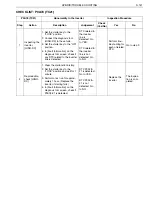
Страница 63: ...ctor 3 Using the electrical tester measure the voltage between the vehi cle side connector terminals of PCU harness 24P NO YES 1 Reading the DTC HINO DX SHTS03ZZZ0300044 Is DTC P060B B2 detected Perform troubleshooting for each of related DTC Go to step 2 2 Inspecting the vehicle wire harness SHTS03ZZZ0300045 Measurement conditions Tester connections Standard values Starter key LOCK PCU harness 24...

Страница 64: ...short cir cuit NO YES 3 Inspecting the PCU wire harness lower side SHTS03ZZZ0300046 Measurement conditions Tester connections Standard values Starter key LOCK HV ECU3 connec tor 1st terminal 5th terminal 10 16 V Is the measured value within the range of standard value Go to step 4 Replace the PCU wire harness lower side 4 Inspecting the signal line of PCU wire harness lower side for short circuit ...

Страница 65: ...nitor on the diagnosis tool screen and monitor Power supply voltage of HV ECU NO YES 5 Inspecting the signal line of PCU wire harness upper side for short circuit Measurement conditions Tester connections Standard values Starter key LOCK PCU harness 16P upper side con nector 16th terminal Each signal line 10 k or more Is any defect found Replace the PCU wire harness upper side Go to step 6 6 Inspe...

Страница 66: ...to the ON position and wait for 1 minute 3 In Fault Information on the diagnosis tool screen check if DTC P0562 71 is detected NO YES 7 Reproduction check HINO DX SHTS03ZZZ0300048 Is DTC P0562 71 detected Re inspect the 12 V battery and power supply circuit The inspection is completed ...

Страница 67: ... the vehicle side connector termi nals of PCU harness 24P Measurement conditions Starter key LOCK Tester connections PCU harness 24P vehicle side connector 2nd terminal 16th terminal Standard values 10 16 V The mea sured value is within the range of stan dard value Go to YES The mea sured value is not within the range of stan dard value Go to NO Go to step 3 Inspect the power supply circuit HV 10 ...

Страница 68: ...e signal line of PCU wire harness upper side for short circuit See Inspecting the PCU harness signal line for short circuit Measurement conditions Starter key ON Tester connections PCU harness 16P upper side connector 16th terminal Each signal line Standard values 10 k or more Defect is found Go to YES Defect is not found Go to NO Replace the PCU wire har ness upper side Go to step 6 6 Inspecting ...

Страница 69: ... Fault Information on the diagnosis tool screen check if DTC P0562 71 is detected DTC P0562 71 is detected Go to YES DTC P0562 71 is not detected Go to NO Re inspect the 12 V battery and power supply circuit The inspec tion is com pleted P0562 TC71 Abnormality in power supply voltage Inspection Procedure Step Action Description Judgement Check Yes No Yes No ...

Страница 70: ...es successively 4 Indication warning or system control regulation when the DTC is set MIL ON HV warning light ON 5 Symptoms on the vehicle when the DTC is set Symptoms on the vehicle due to backup control fail safe Symptoms on the vehicle due to malfunction The idling stop function becomes inoperative The regeneration function stops which may reduce the feeling of deceleration during deceleration ...

Страница 71: ...o the ON position 4 Clear the malfunction history 5 Start the engine and keep it idling for 1 minute 6 In Fault Information on the diagnosis tool screen check if P060B B2 is detected NO YES 1 Reproduction check HINO DX SHTS03ZZZ0300049 Is DTC P060B B2 detected Replace the HV ECU The inspection is completed The abnormal ity may have been caused by a temporary factor such as noise ...

Страница 72: ...ct the diagnosis tool HINO DX to the vehicle 3 Set the starter key to the ON position 4 Clear the malfunction history 5 Start the engine and keep it idling for 1 minute 6 In Fault Information on the diagnosis tool screen check if P060B B2 is detected DTC P060B B2 is detected Go to YES DTC P060B B2 is not detected Go to NO Replace the HV ECU The inspec tion is com pleted The abnormality may have be...

Страница 73: ...00 r min or more The motor revolution sensor shows no abnormality 2 Judgement criteria The starter signal remains ON for 20 seconds or more 3 Reset condition The starter signal remains OFF for 0 1 second or more 4 Indication warning or system control regulation when the DTC is set MIL ON HV warning light ON 5 Symptoms on the vehicle when the DTC is set Symptoms on the vehicle due to backup control...

Страница 74: ... work Clear the recorded DTC Check that no DTC is detected after test driving the vehicle 8 Estimated failure factors Disconnection or short circuit of harness Improper contact or fitting of connector Malfunction of starter key Malfunction of HV ECU ...

Страница 75: ...ound NO YES 1 Inspecting the neutral switch 1 SHTS03ZZZ0300051 Measurement conditions Tester connections Standard values Starter key ON Shift lever N position Neutral switch connector 6th terminal 10th terminal Less than 3 Is the measured value within the range of standard value Go to step 2 Replace the neutral switch 2 Inspecting the neutral switch 2 VEHICLE GND SHTS03ZZZ0300052 Measurement condi...

Страница 76: ... vehicle wire harness for short circuit 1 starter key signal circuit VEHICLE GND SHTS03ZZZ0300053 Measurement conditions Tester connections Standard values Starter key ON Starter key vehi cle side connector 6th terminal GND Less than 1 V Is the measured value within the range of standard value Go to step 4 Repair or replace the wire harness Starter key signal circuit 4 Inspecting the key cylinder ...

Страница 77: ...ness for short circuit 2 starter key signal circuit VEHICLE GND SHTS03ZZZ0300055 Measurement conditions Tester connections Standard values Starter key ON PCU harness 24P vehicle side con nector 12th terminal GND Less than 1 V Is the measured value within the range of standard value Go to step 6 Repair or replace the wire harness Starter key signal circuit 6 Inspecting the PCU wire harness lower si...

Страница 78: ...he engine speed remain at 25 km h or more and 1500 r min or more respectively for 30 seconds or more 6 In Fault Information on the diagnosis tool screen check if P0617 59 is detected NO YES 7 Inspecting the signal line of PCU wire harness lower side for short circuit Measurement conditions Tester connections Standard values Starter key LOCK PCU harness 24P lower side con nector 12th terminal Each ...

Страница 79: ... switch connector 6th terminal 10th terminal Standard values Less than 3 The mea sured value is within the range of stan dard value Go to YES The mea sured value is not within the range of stan dard value Go to NO Go to step 2 Replace the neutral switch 2 Inspecting the neutral switch 2 1 Using the electrical tester mea sure the resistance between each terminal of neutral switch connector and the ...

Страница 80: ...rminal of key cylinder connector and the ground Measurement conditions Starter key ON Tester connections Key cylinder connector 6th terminal GND Standard values Less than 1 V The mea sured value is within the range of stan dard value Go to YES The mea sured value is not within the range of stan dard value Go to NO Go to step 5 Replace the key cylinder 5 Inspecting the vehicle wire harness for shor...

Страница 81: ...it See Inspect ing the PCU harness signal line for short circuit Measurement conditions Starter key LOCK Tester connections PCU harness 24P lower side connector 12th terminal Each signal line Standard values 10 k or more Defect is found Go to YES Defect is not found Go to NO Replace the PCU wire har ness lower side Go to step 8 8 Reproduction check HINO DX 1 Connect all the connectors that have be...

Страница 82: ...PROM 3 Reset condition Successful access to EEPROM 4 Indication warning or system control regulation when the DTC is set MIL ON HV warning light ON 5 Symptoms on the vehicle when the DTC is set Symptoms on the vehicle due to backup control fail safe Symptoms on the vehicle due to malfunction Recording of malfunction code DTC may become unavailable 6 Pre inspection work Check the battery voltage to...

Страница 83: ...YES 1 Clear the malfunction history 2 Set the starter key to the ON position and wait for 1 minute 3 In Fault Information on the diagnosis tool screen check if P062F B3 is detected NO YES 1 Reading the DTC HINO DX SHTS03ZZZ0300058 Is DTC P0562 71 detected Perform troubleshooting for each of related DTC Go to step 2 2 Reproduction check HINO DX SHTS03ZZZ0300059 Is DTC P062F B3 detected Replace the ...

Страница 84: ...DTC P0562 71 other than P062F B3 is detected DTC P0562 71 is detected Go to YES DTC P0562 71 is not detected Go to NO Perform trou bleshooting for each of related DTC Go to step 2 2 Reproduction check HINO DX 1 Clear the malfunction history 2 Set the starter key to the ON position and wait for 1 minute 3 In Fault Information on the diagnosis tool screen check if P062F B3 is detected DTC P062F B3 i...

Страница 85: ...ication that receiving from AT ECU is unavailable and that the communication has been disrupted Notification of abnormality in electric oil pump for the clutch Notification of clutch disengagement abnormality Notification of clutch slip abnormality Notification of clutch revolution alignment abnormality Notification that the HV damper friction material is worn ABS ECU CAN H2 CAN L2 HV PCU HV ECU I...

Страница 86: ...fication of clutch slip abnormality Notification of clutch revolution alignment abnormality Notification that the HV damper friction material is worn 4 Indication warning or system control regulation when the DTC is set MIL OFF HV warning light ON 5 Symptoms on the vehicle when the DTC is set Symptoms on the vehicle due to backup control fail safe Symptoms on the vehicle due to malfunction The idl...

Страница 87: ...DX to the vehicle 3 Set the starter key to the ON position 4 In Fault Information on the diagnosis tool screen check if any DTC other than P0810 9C is detected NO YES 1 Reading the DTC HINO DX SHTS03ZZZ0300061 Is any DTC other than P0810 9C detected Perform troubleshooting for each of related DTC Perform troubleshooting of the clutch ECU ...

Страница 88: ...t the starter key to the LOCK position 2 Connect the diagnosis tool HINO DX to the vehicle 3 Set the starter key to the ON position 4 In Fault Information on the diagnosis tool screen check if any DTC other than P0810 9C is detected DTC other than P0810 9C is detected Go to YES DTC other than P0810 9C is not detected Go to NO Perform trou bleshooting for each of related DTC Perform trou bleshootin...

Страница 89: ...ation that the clutch ECU starter key signal is stuck 3 Reset condition When the notification that there is none of the following abnormality is received from the clutch ECU Notification that the electric oil pump power supply relay for the clutch is stuck to ON Notification that the clutch ECU power supply is stuck Notification that the clutch ECU starter key signal is stuck ABS ECU CAN H2 CAN L2...

Страница 90: ...cle due to backup control fail safe Symptoms on the vehicle due to malfunction The idling stop function may become inoperative 6 Pre inspection work Check the battery voltage to make sure that there is no abnormality 7 After inspection work Clear the recorded DTC Check that any DTC will not be detected after test driving the vehicle 8 Estimated failure factors Malfunctioning of clutch system ...

Страница 91: ...DX to the vehicle 3 Set the starter key to the ON position 4 In Fault Information on the diagnosis tool screen check if any DTC other than P0810 9D is detected NO YES 1 Reading the DTC HINO DX SHTS03ZZZ0300063 Is any DTC other than P0810 9D detected Perform troubleshooting for each of related DTC Perform troubleshooting of the clutch ECU ...

Страница 92: ...t the starter key to the LOCK position 2 Connect the diagnosis tool HINO DX to the vehicle 3 Set the starter key to the ON position 4 In Fault Information on the diagnosis tool screen check if any DTC other than P0810 9D is detected DTC other than P0810 9D is detected Go to YES DTC other than P0810 9D is not detected Go to NO Perform trou bleshooting for each of related DTC Perform trou bleshootin...

Страница 93: ...um of motor current for 20 seconds is 200 000 A2 or more The motor current sensor shows no abnormality The output of inverter start relay is ON 2 Judgement criteria The difference in the inverter coolant temperature Max Min for 20 seconds is less than 0 5 C 32 9 F 3 Reset condition The difference in the inverter coolant temperature Max Min for 20 seconds is 0 5 C 32 9 F or more 4 Indication warnin...

Страница 94: ...the recorded DTC Check that no DTC is detected after test driving the vehicle 8 Estimated failure factors Disconnection or short circuit of harness Malfunction of inverter cooling circuit Malfunction of inverter coolant temperature sensor Malfunction of HV ECU ...
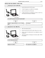
Страница 95: ... height from the coolant level to the filling port NO YES 1 Inspecting the coolant line route Is any defect found Repair or replace the defective part After repair replacement perform the inspec tion again Go to step 2 2 Inspecting the coolant level Is the coolant level about 10 mm from the filling port Go to step 3 Add coolant See Adding coolant After adding coolant perform the inspection again ...

Страница 96: ...emperature sensor 3 Using the electrical tester measure the resistance between the terminals of coolant temperature sensor connector NO YES 3 Reading the DTC HINO DX SHTS03ZZZ0300065 Is any DTC other than P0A01 7B detected Perform troubleshooting for each of related DTC Go to step 4 4 Inspecting the coolant temperature sensor SHTS03ZZZ0300066 Measurement conditions Tester connections Standard valu...

Страница 97: ...or short circuit See Inspecting the PCU harness signal line for short cir cuit NO YES 5 Inspecting the signal line of PCU wire harness lower side for short circuit Measurement conditions Tester connections Standard values Starter key LOCK Coolant tempera ture sensor con nector 2nd terminal Each signal line 10 k or more Is any defect found Replace the PCU wire harness lower side Go to step 6 ...

Страница 98: ...iagnosis tool screen measure HV sys tem coolant temperature NO YES 6 Reproduction check HINO DX SHTS03ZZZ0300067 Measurement conditions Measured item Standard values Starter key ON HV system coolant temperature Equivalent to ambient tempera ture Is the measured value within the range of standard value Replace the HV ECU The inspection is completed If no repair or parts replacement is per formed th...

Страница 99: ... ant level to the filling port Coolant level is about 10 mm from the filling port Go to YES Coolant level is not about 10 mm from the filling port Go to NO Go to step 3 Add coolant See Adding coolant After adding coolant per form the inspection again 3 Reading the DTC HINO DX 1 Set the starter key to the LOCK position 2 Connect the diagnosis tool HINO DX to the vehicle 3 Set the starter key to the...

Страница 100: ... of stan dard value Go to NO Go to step 5 Replace the coolant tem perature sen sor 5 Inspecting the signal line of PCU wire har ness lower side for short circuit 1 Set the starter key to the LOCK position 2 For the 2nd terminal of coolant temperature sensor connector inspect the signal line of PCU wire harness lower side for short circuit See Inspecting the PCU harness signal line for short circui...

Страница 101: ... Starter key ON Measured item HV system coolant temperature Standard values Equivalent to ambient tempera ture The mea sured value is within the range of stan dard value Go to YES The mea sured value is not within the range of stan dard value Go to NO Replace the HV ECU The inspec tion is com pleted If no repair or parts replace ment is per formed there may be an improper con tact due to connector...

Страница 102: ...ns less than 0 2 V for 10 seconds or more 3 Reset condition The voltage of inverter coolant temperature sensor remains at 0 5 V or more for 10 seconds or more 4 Indication warning or system control regulation when the DTC is set MIL ON HV warning light ON 5 Symptoms on the vehicle when the DTC is set Symptoms on the vehicle due to backup control fail safe Symptoms on the vehicle due to malfunction...

Страница 103: ...D TROUBLE SHOOTING 3 99 8 Estimated failure factors Disconnection or short circuit of harness Improper contact or fitting of connector Malfunction of inverter coolant temperature sensor Malfunction of HV ECU ...

Страница 104: ...perature sensor connector and the HV ECU1 connec tor terminal NO YES 1 Inspecting the continuity of PCU wire harness lower side SHTS03ZZZ0300069 Measurement conditions Tester connections Standard values Starter key LOCK Coolant tempera ture sensor con nector HV ECU1 connector 1st terminal 30th terminal 2nd terminal 29th terminal Less than 1 Is the measured value within the range of standard value ...

Страница 105: ...ditions Tester connections Standard values Starter key LOCK Coolant tempera ture sensor con nector 1st terminal GND 2nd terminal GND 10 k or more Is the measured value within the range of standard value Go to step 3 Replace the PCU wire harness lower side 3 Inspecting the PCU wire harness lower side for short circuit 2 SHTS03ZZZ0300071 Measurement conditions Tester connections Standard values Star...

Страница 106: ...Measurement conditions Tester connections Standard values Starter key LOCK Coolant tempera ture sensor connector sen sor side 1st terminal 2nd terminal 0 C 32 F 5 3 k 6 2 k 20 C 68 F 2 3 k 2 6 k 30 C 86 F 1 5k 1 8 k Is the measured value within the range of standard value Go to step 5 Replace the coolant temperature sensor 5 Inspecting the signal line of PCU wire harness lower side for short circu...

Страница 107: ...iagnosis tool screen measure HV sys tem coolant temperature NO YES 6 Reproduction check HINO DX SHTS03ZZZ0300073 Measurement conditions Measured item Standard values Starter key ON HV system coolant temperature Equivalent to ambient tempera ture Is the measured value within the range of standard value Replace the HV ECU The inspection is completed If no repair or parts replacement is per formed th...

Страница 108: ...e 2 Inspecting the PCU wire har ness lower side for short circuit 1 1 Using the electrical tester mea sure the resistance between each terminal of coolant tem perature sensor connector and the ground Measurement conditions Starter key LOCK Tester connections Coolant temperature sensor con nector 1st terminal GND 2nd terminal GND Standard values 10 k or more The mea sured value is within the range ...

Страница 109: ...ey LOCK Tester connections Coolant temperature sensor con nector 2nd terminal Each signal line Standard values 10 k or more Defect is found Go to YES Defect is not found Go to NO Replace the PCU wire har ness lower side Go to step 6 6 Reproduction check HINO DX 1 Connect all the connectors that have been disconnected to restore the system 2 Connect the diagnosis tool HINO DX to the vehicle 3 Set t...

Страница 110: ...e speed remains at 600 r min or more for 60 seconds or more The vehicle speed remains at 12 4 mph or more for 30 seconds or more 2 Judgement criteria The voltage of inverter coolant temperature sensor remains above 4 8 V for 10 seconds or more 3 Reset condition The voltage of inverter coolant temperature sensor remains at 4 5 V or less for 10 seconds or more 4 Indication warning or system control ...

Страница 111: ...the recorded DTC Check that no DTC is detected after test driving the vehicle 8 Estimated failure factors Disconnection or short circuit of harness Improper contact or fitting of connector Malfunction of inverter coolant temperature sensor Malfunction of HV ECU ...
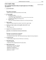
Страница 112: ...perature sensor connector and the HV ECU1 connec tor terminal NO YES 1 Inspecting the continuity of PCU wire harness lower side SHTS03ZZZ0300075 Measurement conditions Tester connections Standard values Starter key LOCK Coolant tempera ture sensor con nector HV ECU1 connector 1st terminal 30th terminal 2nd terminal 29th terminal Less than 1 Is the measured value within the range of standard value ...

Страница 113: ...easurement conditions Tester connections Standard values Starter key LOCK Coolant tempera ture sensor con nector sensor side 1st terminal 2nd terminal 0 C 32 F 5 3 k 6 2 k 20 C 68 F 2 3 k 2 6 k 30 C 86 F 1 5 k 1 8 k Is the measured value within the range of standard value Go to step 3 Replace the coolant temperature sensor 3 Inspecting the signal line of PCU wire harness lower side for short circu...

Страница 114: ...gnosis tool screen measure HV sys tem coolant temperature NO YES 4 Reproduction check HINO DX SHTS03ZZZ0300077 Measurement conditions Tester connections Standard values Starter key ON HV system coolant temperature Equivalent to ambient tempera ture Is the measured value within the range of standard value Replace the HV ECU The inspection is completed If no repair or parts replacement is per formed...

Страница 115: ...olant tem perature sen sor 1 Using the electrical tester mea sure the resistance of coolant temperature sensor Measurement conditions Starter key LOCK Tester connections Coolant temperature sensor con nector sensor side 1st terminal 2nd terminal Standard values 0 C 32 F 5 3 k 6 2 k 20 C 68 F 2 3 k 2 6 k 30 C 86 F 1 5 k 1 8 k The mea sured value is within the range of stan dard value Go to YES The ...

Страница 116: ... conditions Starter key ON Tester connections HV system coolant temperature Standard values Equivalent to ambient tempera ture The mea sured value is within the range of stan dard value Go to YES The mea sured value is not within the range of stan dard value Go to NO Replace the HV ECU The inspec tion is com pleted If no repair or parts replace ment is per formed there may be an improper con tact ...

Страница 117: ...s met continuously for 0 5 second or more Input signal for monitoring HV water pump drive signal is 0 Hz Input signal for monitoring HV water pump drive signal is less than 0 2 V 3 Reset condition Input signal for monitoring HV water pump drive signal remains at 1 Hz or more for 5 seconds or more 4 Indication warning or system control regulation when the DTC is set MIL ON HV warning light ON 5 Sym...

Страница 118: ...n work Clear the recorded DTC Check that no DTC is detected after test driving the vehicle 8 Estimated failure factors Disconnection or short circuit of harness Improper connector contact or fitting Malfunction of HV water pump Malfunction of HV ECU ...
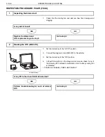
Страница 119: ...reen select HV water pump drive duty value 2 Run the inverter cooling pump at a duty value of 90 to check that the cooling fan is rotating NO YES 1 Reading the DTC HINO DX SHTS03ZZZ0300079 Is DTC P324B 62 or P324C 61 detected Perform troubleshooting for each of related DTC Go to step 2 2 Checking the activation of inverter cooling pump HINO DX SHTS03ZZZ0300080 Measurement conditions Measured item ...

Страница 120: ... 24P vehicle side connector and the ground NO YES 3 Inspecting the voltage of vehicle wire harness VEHICLE GND SHTS03ZZZ0300081 Measurement conditions Tester connections Standard values Starter key LOCK PCU harness 24P vehicle side con nector 3rd terminal GND 9 V or more Is the measured value within the range of standard value Go to step 4 Inspect the power supply circuit PCU B2 20A fuse and wire ...

Страница 121: ...the 1st and 2nd terminals of inverter start relay and measure the resistance between the 3rd and 5th terminals With voltage applied NO YES 4 Inspecting the inverter start relay 3 5 1 2 SHTS03ZZZ0300082 Measurement conditions Tester connections Standard values Starter key LOCK Inverter start relay 3rd terminal 5th terminal Without voltage 10 k or more With voltage less than 1 Is the measured value ...

Страница 122: ...sing the electrical tester measure the voltage between the con nector terminals of inverter cooling pump NO YES 5 Inspecting the voltage of PCU wire harness lower side SHTS03ZZZ0300083 Measurement conditions Tester connections Standard values Starter key ON Inverter cooling pump connector 1st terminal 4th terminal 9 V or more Is the measured value within the range of standard value Go to step 6 Re...

Страница 123: ...de SHTS03ZZZ0300084 Measurement conditions Tester connections Standard values Starter key LOCK Inverter cooling pump connector HV ECU2 connec tor 3rd terminal 17th terminal Less than 1 Is the measured value within the range of standard value Go to step 7 Replace the PCU wire harness lower side 7 Inspecting the PCU wire harness lower side for short circuit VEHICLE GND SHTS03ZZZ0300085 Measurement c...

Страница 124: ...story 5 Set the starter key to the ON position and wait for 1 minute 6 In Fault Information on the diagnosis tool screen check if P0A06 7F is detected NO YES 8 Inspecting the signal line of PCU wire harness lower side for short circuit Measurement conditions Tester connections Standard values Starter key LOCK Inverter cooling pump connector 3rd terminal Each signal line 10 k or more Is any defect ...

Страница 125: ... the inverter cooling pump at a duty value of 90 to check that the cooling fan is rotating Measurement conditions Starter key ON Measured item HV water pump drive duty value Standard values The cooling fan is running rotat ing Cooling fan is running Go to YES Cooling fan is not run ning Go to NO Go to step 6 Go to step 3 3 Inspecting the voltage of vehicle wire harness 1 Set the starter key to the...

Страница 126: ...within the range of stan dard value Go to NO Go to step 5 Replace the inverter start relay 5 Inspecting the voltage of PCU wire har ness lower side 1 Set the starter key to the LOCK position 2 Connect the PCU harness 24P connector and the inverter start relay 3 Disconnect the inverter cooling pump connector 4 Set the starter key to the ON position 5 Using the electrical tester mea sure the voltage...

Страница 127: ...ND Measurement conditions Starter key LOCK Tester connections Inverter cooling pump connector 3rd terminal GND Standard values 10 k or more The mea sured value is within the range of stan dard value Go to YES The mea sured value is not within the range of stan dard value Go to NO Go to step 8 Replace the PCU wire har ness lower side 8 Inspecting the signal line of PCU wire har ness lower side for ...

Страница 128: ...on 4 Clear the malfunction history 5 Set the starter key to the ON position and wait for 1 minute 6 In Fault Information on the diagnosis tool screen check if P0A06 7F is detected DTC P0A06 7F is detected Go to YES DTC P0A06 7F is not detected Go to NO Replace the HV ECU The inspec tion is com pleted P0A06 TC7F HV water pump drive signal Low abnormality Inspection Procedure Step Action Description...

Страница 129: ...is set to the ON position The control power supply voltage is 10 V or more The requested drive duty of HV water pump is above 0 The output of inverter start relay is ON 2 Judgement criteria When one of the following conditions is met Condition 1 Input signal for monitoring HV water pump drive signal remains above 4 6 V for 0 1 second or more Condition 2 The following conditions are met continuousl...

Страница 130: ...tion when the DTC is set MIL ON HV warning light ON 5 Symptoms on the vehicle when the DTC is set Symptoms on the vehicle due to backup control fail safe Symptoms on the vehicle due to malfunction 6 Pre inspection work Check the battery voltage to make sure that there is no abnormality 7 After inspection work Clear the recorded DTC Check that no DTC is detected after test driving the vehicle 8 Est...

Страница 131: ... ON position 4 Clear the malfunction history 5 Set the starter key to the LOCK position and wait for 1 minute 6 Set the starter key to the ON position and wait for 1 minute 7 In Fault Information on the diagnosis tool screen check if P0A07 7E is detected NO YES 1 Inspecting the signal line of PCU wire harness lower side for short circuit Measurement conditions Tester connections Standard values St...

Страница 132: ...s Inverter cooling pump connector 3rd terminal Each signal line Standard values 10 k or more Defect is found Go to YES Defect is not found Go to NO Replace the PCU wire har ness lower side Replace the inverter cool ing pump After replace ment go to step 2 2 Reproduction check HINO DX 1 Connect all the connectors that have been disconnected to restore the system 2 Connect the diagnosis tool HINO DX...

Страница 133: ... The engine coolant temperature or HV battery minimum temperature remains below 10 C 14 F for 8 seconds or more 3 Reset condition V control mode information is not When starting the engine The engine speed remains at 650 r min or more for 1 second or more 4 Indication warning or system control regulation when the DTC is set MIL OFF HV warning light OFF 5 Symptoms on the vehicle when the DTC is set...

Страница 134: ... tool screen check if any engine system DTC is detected NO YES 1 Check the fuel meter in the combination meter to make sure that the fuel level is Lo level or above NO YES 1 Inspecting the engine ECU HINO DX SHTS03ZZZ0300089 Is any DTC detected from the engine ECU Perform troubleshooting for each DTC of engine ECU Go to step 2 2 Inspecting the fuel level Is the fuel level at Lo level or above Go t...

Страница 135: ...e to read the HV battery temperature 2 Continue cranking for 5 seconds if HV battery minimum tempera ture is 10 C 14 F or more and for 8 seconds if below 10 C 14 F to check that the engine starts NO YES 3 Reproduction check HINO DX SHTS03ZZZ0300090 Did the engine start The inspection is completed Inspect the engine ECU ...

Страница 136: ...u bleshooting for each DTC of engine ECU Go to step 2 2 Inspecting the fuel level 1 Check the fuel meter in the combination meter to make sure that the fuel level is Lo level or above Fuel level is Lo level or above Go to YES Fuel level is not Lo level or above Go to NO Go to step 3 Fill the fuel and go to step 3 3 Reproduction check HINO DX 1 In the Data Monitor on the diagnosis tool screen selec...

Страница 137: ...nd writing of the control CAN controller ID message register are normally executed 4 Indication warning or system control regulation when the DTC is set MIL ON Diag lamp ON 5 Symptoms on the vehicle when the DTC is set Symptoms on the vehicle due to backup control fail safe Symptoms on the vehicle due to malfunction The idling stop function becomes inoperative The regeneration function stops which...

Страница 138: ...ar the malfunction history 5 Set the starter key to the LOCK position and wait for 1 minute 6 Set the starter key to the ON position 7 In Fault Information on the diagnosis tool screen check if P0A1D 12 is detected NO YES 1 Reproduction check HINO DX SHTS03ZZZ0300091 Is DTC P0A1D 12 detected Replace the HV ECU The inspection is completed Temporary actuation of protection function due to external n...

Страница 139: ...HINO DX to the vehicle 3 Set the starter key to the ON position 4 Clear the malfunction history 5 Set the starter key to the LOCK position and wait for 1 minute 6 Set the starter key to the ON position 7 In Fault Information on the diagnosis tool screen check if P0A1D 12 is detected DTC P0A1D 12 is detected Go to YES DTC P0A1D 12 is not detected Go to NO Replace the HV ECU The inspec tion is com p...

Страница 140: ...iting of the DIAG CAN controller ID message register are normally executed 4 Indication warning or system control regulation when the DTC is set MIL ON HV warning light ON 5 Symptoms on the vehicle when the DTC is set Symptoms on the vehicle due to backup control fail safe Symptoms on the vehicle due to malfunction The idling stop function becomes inoperative The regeneration function stops which ...

Страница 141: ...rter key to the LOCK position and wait for 1 minute 6 Set the starter key to the ON position 7 In Fault Information on the diagnosis tool screen check if P0A1D 17 is detected NO YES 1 Reproduction check HINO DX SHTS03ZZZ0300092 Is DTC P0A1D 17 detected Replace the HV ECU Take the same steps when communication with the diagnosis tool is not available The inspection is completed Temporary actuation ...

Страница 142: ... key to the ON position 4 Clear the malfunction history 5 Set the starter key to the LOCK position and wait for 1 minute 6 Set the starter key to the ON position 7 In Fault Information on the diagnosis tool screen check if P0A1D 17 is detected DTC P0A1D 17 is detected Go to YES DTC P0A1D 17 is not detected Go to NO Replace the HV ECU Take the same steps when commu nication with the diagnosis tool ...

Страница 143: ...mmunication 4 Indication warning or system control regulation when the DTC is set MIL OFF HV warning light ON 5 Symptoms on the vehicle when the DTC is set Symptoms on the vehicle due to backup control fail safe Symptoms on the vehicle due to malfunction The idling stop function becomes inoperative Note however that vehicles equipped with a starter will be started with the starter Idling stop may ...

Страница 144: ...nction history 2 Set the starter key to the LOCK position and wait for 1 minute 3 Perform a test run for approximately 1 hour Replace the inverter if starting fails 4 In Fault Information on the diagnosis tool screen check if P0A78 21 is detected NO YES 1 Inspecting the inverter HINO DX SHTS03ZZZ0300093 Is any DTC related to the inverter line detected Perform troubleshooting for each of related DT...

Страница 145: ... inverter line is detected DTC related to the inverter line is detected Go to YES DTC related to the inverter line is not detected Go to NO Perform trou bleshooting for each of related DTC Go to step 2 2 Reproduction check HINO DX 1 Clear the malfunction history 2 Set the starter key to the LOCK position and wait for 1 minute 3 Perform a test run for approxi mately 1 hour Replace the inverter if s...

Страница 146: ...munication 4 Indication warning or system control regulation when the DTC is set MIL OFF HV warning light ON 5 Symptoms on the vehicle when the DTC is set Symptoms on the vehicle due to backup control fail safe Symptoms on the vehicle due to malfunction The engine may become unable to start Note however that vehicles equipped with a starter will be started with the starter Idling stop may become u...

Страница 147: ...nction history 2 Set the starter key to the LOCK position and wait for 1 minute 3 Perform a test run for approximately 1 hour Replace the inverter if starting fails 4 In Fault Information on the diagnosis tool screen check if P0A78 22 is detected NO YES 1 Inspecting the inverter HINO DX SHTS03ZZZ0300095 Is any DTC related to the inverter line detected Perform troubleshooting for each of related DT...

Страница 148: ... inverter line is detected DTC related to the inverter line is detected Go to YES DTC related to the inverter line is not detected Go to NO Perform trou bleshooting for each of related DTC Go to step 2 2 Reproduction check HINO DX 1 Clear the malfunction history 2 Set the starter key to the LOCK position and wait for 1 minute 3 Perform a test run for approxi mately 1 hour Replace the inverter if s...

Страница 149: ...s to be within the standard range 4 Indication warning or system control regulation when the DTC is set MIL ON HV warning light ON 5 Symptoms on the vehicle when the DTC is set Symptoms on the vehicle due to backup control fail safe Symptoms on the vehicle due to malfunction The idling stop function becomes inoperative The regeneration function stops which may reduce the feeling of deceleration du...

Страница 150: ...e ON position 4 In Fault Information on the diagnosis tool screen check if any of the following DTC related to malfunction of HV battery cooling fan is detected P0A84 66 P0A65 65 P0BCA 68 P0A82 67 NO YES 1 Inspecting the blower duct Is any defect found Replace the blower duct After replacement go to step 2 Go to step 2 2 Reading the DTC HINO DX SHTS03ZZZ0300097 Is any DTC other than P0A7E 48 detec...

Страница 151: ...e of 90 to check that the cooling fan is rotating NO YES 3 Inspecting the HV battery ECU HINO DX SHTS03ZZZ0300098 Is any DTC related to the HV battery temperature sensor detected Perform troubleshooting for each of related DTC Go to step 4 4 Inspecting the operation of HV battery cooling fan HINO DX SHTS03ZZZ0300099 Measurement conditions Measured item Standard values Starter key ON HV battery coo...

Страница 152: ... 48 is detected NO YES 5 Inspecting the HV battery temperature sensor HINO DX SHTS03ZZZ0300100 Measurement conditions Measured item Standard values Starter key ON After cooling idling state Maximum temper ature of HV battery Less than 80 C 176 F Is the measured value within the range of standard value Go to step 6 Replace the HV battery ECU After replacement go to step 6 6 Reproduction check HINO ...

Страница 153: ...r than P0A7E 48 is not detected Go to NO Perform trou bleshooting for each of related DTC Go to step 3 3 Inspecting the HV battery ECU HINO DX 1 Select Fault Information on the diagnosis tool screen check if any DTC related to the HV battery temperature sensor is detected in the HV battery ECU DTC related to the HV battery temperature sensor is detected Go to YES DTC related to the HV battery temp...

Страница 154: ...ured value is not within the range of stan dard value Go to NO Go to step 6 Replace the HV battery ECU After replace ment go to step 6 6 Reproduction check HINO DX 1 Restore the system 2 Clear the malfunction history 3 Perform a test run for approxi mately 1 hour 4 In Fault Information on the diagnosis tool screen check if P0A7E 48 is detected DTC P0A7E 48 is detected Go to YES DTC P0A7E 48 is not...

Страница 155: ...ly for 10 seconds or more The number of revolution of the HV battery cooling fan is higher than the upper limit The number of revolution of the HV battery cooling fan is lower than the lower limit For the upper and lower limits see below Lower limit HV battery cooling fan drive duty of 20 252 0 r min HV battery cooling fan drive duty of 30 595 0 r min HV battery cooling fan drive duty of 40 892 0 ...

Страница 156: ... min HV battery cooling fan drive duty of 50 1150 0 r min HV battery cooling fan drive duty of 60 1391 0 r min HV battery cooling fan drive duty of 70 1609 0 r min HV battery cooling fan drive duty of 80 1802 0 r min HV battery cooling fan drive duty of 90 1976 0 r min Upper limit HV battery cooling fan drive duty of 20 1416 7 r min HV battery cooling fan drive duty of 30 1886 3 r min HV battery c...

Страница 157: ...HYBRID TROUBLE SHOOTING 3 153 8 Estimated failure factors Disconnection or short circuit of harness Improper connector connection or fitting Malfunction of HV battery cooling fan Malfunction of HV ECU ...
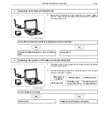
Страница 158: ...to the ON position 4 In Fault Information on the diagnosis tool screen check if any of the following DTC related to malfunction of HV battery cooling fan is detected P0A84 66 P0A65 65 P0BCA 68 NO YES 1 Inspecting the blower duct Is any defect found Replace the blower duct After replacement go to step 2 Go to step 2 2 Reading the DTC HINO DX SHTS03ZZZ0300103 Is any DTC other than P0A82 67 detected ...

Страница 159: ...at each duty value NO YES 3 Inspecting the operation of HV battery cooling fan HINO DX SHTS03ZZZ0300104 Measurement conditions Measured item Standard values Starter key ON HV battery cool ing fan duty value The cooling fan is running rotating Is the cooling fan running Go to step 4 Replace the HV battery cooling fan 4 Checking the number of revolutions of HV battery cooling fan HINO DX SHTS03ZZZ03...

Страница 160: ...harness lower side SHTS03ZZZ0300106 Measurement conditions Tester connections Standard values Starter key LOCK HV ECU1 connec tor PCU harness 16P lower side connector 24th terminal 12th terminal Less than 1 Is the measured value within the range of standard value Go to step 6 Replace the PCU wire harness lower side 6 Inspecting the PCU wire harness lower side for short circuit VEHICLE GND SHTS03ZZ...

Страница 161: ... the signal line of PCU wire harness lower side for short circuit Measurement conditions Tester connections Standard values Starter key LOCK PCU harness 16P lower side con nector 12th terminal Each signal line 10 k or more Is any defect found Replace the PCU wire harness lower side Go to step 8 8 Inspecting the continuity of PCU wire harness upper side SHTS03ZZZ0300108 Measurement conditions Teste...

Страница 162: ...signal line for short cir cuit NO YES 9 Inspecting the signal line of PCU wire harness upper side for short circuit Measurement conditions Tester connections Standard values Starter key LOCK PCU harness 16P upper side con nector 12th terminal Each signal line 10 k or more Is any defect found Replace the PCU wire harness upper side Replace the HV battery cooling fan After replacement go to step 10 ...

Страница 163: ... min ute 6 Run the HV battery cooling fan at the duty value of 90 for 1 min ute 7 Set the starter key to the LOCK position and wait for 1 minute 8 Set the starter key to the ON position 9 Run the HV battery cooling fan at the duty value of 20 for 1 min ute 10 Run the HV battery cooling fan at the duty value of 90 for 1 min ute 11 In Fault Information on the diagnosis tool screen check if P0A82 67 ...

Страница 164: ...iagnosis tool screen check if any of the following DTC related to malfunction of HV battery cooling fan is detected P0A84 66 P0A65 65 P0BCA 68 DTC other than P0A82 67 is detected Go to YES DTC other than P0A82 67 is not detected Go to NO Perform trou bleshooting for each of related DTC Go to step 3 3 Inspecting the operation of HV battery cooling fan HINO DX 1 From Activation Test on the diagnosis...

Страница 165: ...r mea sure the resistance between the HV ECU1 connector and the lower side connector termi nal of PCU harness 16P Measurement conditions Starter key LOCK Tester connections HV ECU1 connector PCU har ness 16P lower side connector 24th terminal 12th terminal Standard values Less than 1 The mea sured value is within the range of stan dard value Go to YES The mea sured value is not within the range of...

Страница 166: ...ey LOCK Tester connections PCU harness 16P upper side connector HV battery cooling fan connector 12th terminal 2nd terminal Standard values Less than 1 The mea sured value is within the range of stan dard value Go to YES The mea sured value is not within the range of stan dard value Go to NO Go to step 9 Replace the PCU wire har ness upper side 9 Inspecting the signal line of PCU wire har ness upp...

Страница 167: ...uty value of 90 for 1 minute 7 Set the starter key to the LOCK position and wait for 1 minute 8 Set the starter key to the ON position 9 Run the HV battery cooling fan at the duty value of 20 for 1 minute 10 Run the HV battery cooling fan at the duty value of 90 for 1 minute 11 In Fault Information on the diagnosis tool screen check if P0A82 67 is detected DTC P0A82 67 is detected Go to YES DTC P0...

Страница 168: ... battery ECU start relay is ON 2 Judgement criteria The following conditions are met continuously for 0 5 second or more Input signal for monitoring HV battery cooling fan drive signal is 0 Hz Input signal for monitoring HV battery cooling fan drive signal is less than 0 2V 3 Reset condition Input signal for monitoring HV battery cooling fan drive signal remains at 1 Hz or more for 5 seconds or mo...

Страница 169: ...ion 6 Pre inspection work Check the battery voltage to make sure that there is no abnormality 7 After inspection work Clear the recorded DTC Check that no DTC is detected after test driving the vehicle 8 Estimated failure factors Disconnection or short circuit of harness Improper connector connection or fitting Malfunction of HV battery cooling fan Malfunction of HV ECU ...

Страница 170: ...starter key to the ON position 4 Using the electrical tester measure the voltage between the 1st terminal of PCU harness 24P vehicle side connector and the ground NO YES 1 Reading the DTC HINO DX SHTS03ZZZ0300111 Is any DTC other than P0A84 66 detected Perform troubleshooting for each of related DTC Go to step 2 2 Inspecting the voltage of vehicle wire harness VEHICLE GND SHTS03ZZZ0300112 Measurem...

Страница 171: ...e 1st and 2nd terminals of HV battery start relay and measure the resistance between the 3rd and 5th terminals With voltage applied NO YES 3 Inspecting the HV battery start relay 3 5 1 2 SHTS03ZZZ0300113 Measurement conditions Tester connections Standard values Starter key LOCK HV battery start relay 3rd terminal 5th terminal Without voltage 10 k or more With voltage less than 1 Is the measured va...

Страница 172: ...asure the voltage between the lower side connector terminals of PCU harness 16P NO YES 4 Inspecting the voltage of PCU wire harness lower side SHTS03ZZZ0300114 Measurement conditions Tester connections Standard values Starter key ON PCU harness 16P lower side con nector 9th terminal 15th terminal 9 V or more Is the measured value within the range of standard value Go to step 5 Replace the PCU wire...

Страница 173: ...lower side SHTS03ZZZ0300115 Measurement conditions Tester connections Standard values Starter key LOCK PCU harness 16P lower side con nector HV ECU2 connector 11th terminal 18th terminal Less than 1 Is the measured value within the range of standard value Go to step 6 Replace the PCU wire harness lower side 6 Inspecting the PCU wire harness lower side for short circuit VEHICLE GND SHTS03ZZZ0300116...

Страница 174: ...e con nector terminals of HV battery cooling fan NO YES 7 Inspecting the signal line of PCU wire harness lower side for short circuit Measurement conditions Tester connections Standard values Starter key LOCK PCU harness 16P lower side con nector 11th terminal Each signal line 10 k or more Is any defect found Replace the PCU wire harness lower side Go to step 8 8 Inspecting the voltage of PCU wire...

Страница 175: ...the ON position 5 Clear the malfunction history 6 Set the starter key to the LOCK position and wait for 1 minute 7 Set the starter key to the ON position 8 In Fault Information on the diagnosis tool screen check if P0A84 66 is detected NO YES 9 Inspecting the signal line of PCU wire harness upper side for short circuit Measurement conditions Tester connections Standard values Starter key LOCK PCU ...

Страница 176: ...her than P0A84 66 is not detected Go to NO Perform trou bleshooting for each of related DTC Go to step 2 2 Inspecting the voltage of vehicle wire harness 1 Set the starter key to the LOCK position 2 Disconnect the PCU harness 24P connector 3 Set the starter key to the ON position 4 Using the electrical tester mea sure the voltage between the 1st terminal of PCU harness 24P vehicle side connector a...

Страница 177: ...ed value is not within the range of stan dard value Go to NO Go to step 4 Replace the HV battery start relay 4 Inspecting the voltage of PCU wire har ness lower side 1 Connect the PCU harness 24P connector and the HV battery start relay 2 Disconnect the PCU harness 16P connector 3 Set the starter key to the ON position 4 Using the electrical tester mea sure the voltage between the lower side conne...

Страница 178: ... PCU harness 16P and the ground Measurement conditions Starter key LOCK Tester connections PCU harness 16P lower side connector 11th terminal GND Standard values 10 k or more The mea sured value is within the range of stan dard value Go to YES The mea sured value is not within the range of stan dard value Go to NO Go to step 7 Replace the PCU wire har ness lower side 7 Inspecting the signal line o...

Страница 179: ...o to step 9 Replace the PCU wire har ness upper side 9 Inspecting the signal line of PCU wire har ness upper side for short circuit 1 Set the starter key to the LOCK position 2 Disconnect the PCU harness 16P connector 3 For the 11th terminal of PCU upper side wire harness con nector inspect the signal line of PCU wire harness upper side for short circuit See Inspect ing the PCU harness signal line...

Страница 180: ...lear the malfunction history 6 Set the starter key to the LOCK position and wait for 1 minute 7 Set the starter key to the ON position 8 In Fault Information on the diagnosis tool screen check if P0A84 66 is detected DTC P0A84 66 is detected Go to YES DTC P0A84 66 is not detected Go to NO Replace the HV ECU The inspec tion is com pleted P0A84 TC66 Abnormality in HV battery cooling fan drive signal...

Страница 181: ...Condition B The starter key is set to the ON position The control power supply voltage is 10 V or more 2 Judgement criteria When one of the following conditions is met Condition A Input signal for monitoring HV battery cooling fan drive signal remains higher than 3 6 V for 0 1 second or more Condition B The following conditions are met continuously for 0 5 second or more Input signal for monitorin...

Страница 182: ...DTC is set MIL ON HV warning light ON 5 Symptoms on the vehicle when the DTC is set Symptoms on the vehicle due to backup control fail safe Symptoms on the vehicle due to malfunction 6 Pre inspection work Check the battery voltage to make sure that there is no abnormality 7 After inspection work Clear the recorded DTC Check that no DTC is detected after test driving the vehicle 8 Estimated failure...

Страница 183: ...ct the signal line of PCU wire harness lower side for short circuit See Inspecting the PCU harness signal line for short cir cuit NO YES 1 Inspecting the signal line of PCU wire harness lower side for short circuit Measurement conditions Tester connections Standard values Starter key LOCK PCU harness 16P lower side con nector 11th terminal Each signal line 10 k or more Is any defect found Replace ...

Страница 184: ...tion history 6 Set the starter key to the LOCK position and wait for 1 minute 7 Set the starter key to the ON position 8 In Fault Information on the diagnosis tool screen check if P0A85 65 is detected NO YES 2 Inspecting the signal line of PCU wire harness upper side for short circuit Measurement conditions Tester connections Standard values Starter key LOCK PCU harness 16P upper side con nector 1...

Страница 185: ...key LOCK Tester connections PCU harness 16P lower side connector 11th terminal Each signal line Standard values 10 k or more Defect is found Go to YES Defect is not found Go to NO Replace the PCU wire har ness lower side Go to step 2 2 Inspecting the signal line of PCU wire har ness upper side for short circuit 1 For the 11th terminal of PCU harness 16P upper side con nector inspect the signal lin...

Страница 186: ...ear the malfunction history 6 Set the starter key to the LOCK position and wait for 1 minute 7 Set the starter key to the ON position 8 In Fault Information on the diagnosis tool screen check if P0A85 65 is detected DTC P0A85 65 is detected Go to YES DTC P0A85 65 is not detected Go to NO Replace the HV ECU The inspec tion is com pleted P0A85 TC65 Abnormality in HV battery cooling fan drive signal ...

Страница 187: ...e motor torque is higher than 100 Nm No SMR OFF is requested No GATE is requested SMR 1 is OFF SMR 2 is ON SMR 3 is ON 2 Judgement criteria The following condition occurs twice during 1 DCY The difference between the requested torque and the effective torque remains larger than 100 Nm for 3 sec onds 3 Reset condition The difference between the requested torque and the effective torque remains at 1...

Страница 188: ...tarted with the starter Idling stop is not available The regeneration function stops which may reduce the feeling of deceleration during deceleration 6 Pre inspection work Check the battery voltage to make sure that there is no abnormality 7 After inspection work Clear the recorded DTC Check that no DTC is detected after test driving the vehicle 8 Estimated failure factors Disconnection or short c...

Страница 189: ...k if any DTC related to the inverter line is detected NO YES 1 Set the starter key to the LOCK position 2 Disconnect the service plug and wait for 7 minutes or more NO YES 1 Inspecting the inverter HINO DX SHTS03ZZZ0300122 Is any DTC related to the inverter line detected Perform troubleshooting for each of related DTC Go to step 2 2 Preparation for inspection Is the inspection preparation complete...

Страница 190: ...specting the continuity of three phase cable 1 W V U SHTS03ZZZ0300123 Measurement conditions Tester connections Standard values Starter key LOCK Three phase cable U terminal U terminal V terminal V terminal W terminal W terminal Less than 1 Is the measured value within the range of standard value Go to step 4 When the central terminal block is pro vided Go to step 7 When no central terminal block ...

Страница 191: ...n resistance of three phase cable 1 W V U SHTS03ZZZ0300124 Measurement conditions Tester connections Standard values Starter key LOCK Three phase cable U terminal V terminal V terminal W terminal W terminal U terminal 10 M or more Is the measured value within the range of standard value Go to step 5 When the central terminal block is pro vided Go to step 8 When no central terminal block is pro vid...

Страница 192: ...orm a test run Repeat the following cycle 10 times or more Stop the vehicle Acceleration to 40 km h Deceleration Stop the vehicle 6 In Fault Information on the diagnosis tool screen check if P0A90 2A is detected NO YES 5 Inspecting the resistance between the HV motor phases SHTS03ZZZ0300125 Measurement conditions Tester connections Standard values Starter key LOCK 8 hours after the vehicle has sto...

Страница 193: ...otor side NO YES 7 Inspecting the continuity of three phase cable 2 W V U SHTS03ZZZ0300127 Measurement conditions Tester connections Standard values Starter key LOCK Three phase cable on the HV motor side U terminal U terminal V terminal V terminal W terminal W terminal Less than 1 Is the measured value within the range of standard value Replace the three phase cable on the inverter side Replace t...

Страница 194: ...ted to avoid contact NO YES 8 Inspecting the insulation resistance of three phase cable 2 W V U SHTS03ZZZ0300128 Measurement conditions Tester connections Standard values Starter key LOCK Three phase cable on the HV motor side U terminal V terminal V terminal W terminal W terminal U terminal 10 M or more Is the measured value within the range of standard value Replace the three phase cable on the ...

Страница 195: ...t the service plug and wait for 7 minutes or more Inspection preparation is completed Go to YES Inspection preparation is not com pleted Go to NO Go to step 3 Perform the inspection preparation again 3 Inspecting the continuity of three phase cable 1 1 Disconnect the three phase cable U V and W terminals from the inverter and HV motor 2 Using the electrical tester mea sure the resistance between t...

Страница 196: ... ter minal block is provided Replace the three phase cable 5 Inspecting the resistance between the HV motor phases 1 Using the electrical tester mea sure the resistance between the HV motor terminals HINT If the motor temperature is too high the resistance will change largely Therefore measure the resistance at least 8 hours after the vehicle has stopped Measurement conditions Starter key LOCK 8 h...

Страница 197: ... pleted 7 Inspecting the continuity of three phase cable 2 1 Disconnect the three phase cable U V and W terminals from the relay terminal block 2 Using the electrical tester mea sure the resistance between the terminals of both ends of the three phase cable on the HV motor side Measurement conditions Starter key LOCK Tester connections Three phase cable on the HV motor side U terminal U terminal V...

Страница 198: ...ns Starter key LOCK 8 hours after the vehicle has stopped Tester connections Three phase cable on the HV motor side U terminal V terminal V terminal W terminal W terminal U terminal Standard values 10 M or more The mea sured value is within the range of stan dard value Go to YES The mea sured value is not within the range of stan dard value Go to NO Replace the three phase cable on the inverter si...

Страница 199: ...HV battery current sensor shows no abnormality The HV battery voltage detection circuit has no abnormality GATE is ON The output of inverter start relay is ON No SMR OFF is requested No GATE is requested SMR 1 is OFF SMR 2 is ON SMR 3 is ON 2 Judgement criteria The state in which one of the following conditions is met continuously for 3 seconds or more occurs twice in 1 DCY Charging power generate...

Страница 200: ... HV warning light ON 5 Symptoms on the vehicle when the DTC is set Symptoms on the vehicle due to backup control fail safe Symptoms on the vehicle due to malfunction 6 Pre inspection work Check the battery voltage to make sure that there is no abnormality 7 After inspection work Clear the recorded DTC Check that no DTC is detected after test driving the vehicle 8 Estimated failure factors Malfunct...

Страница 201: ... inverter line is detected NO YES 1 In Fault Information on the diagnosis tool screen check if any DTC related to the HV battery line is detected NO YES 1 Inspecting the inverter HINO DX SHTS03ZZZ0300130 Is any DTC related to the inverter line detected Perform troubleshooting for each of related DTC Go to step 2 2 Inspecting the HV battery ECU HINO DX SHTS03ZZZ0300131 Is any DTC related to the HV ...

Страница 202: ...r measure the insulation resistance between each terminal of high voltage J B in the battery pack and the ground NO YES 3 Preparation for inspection Is the inspection preparation completed Go to step 4 Perform the inspection preparation again 4 Inspecting the HV battery BATT IN 4 BATT IN 3 SHTS03ZZZ0300132 Measurement conditions Tester connections Standard values Starter key LOCK High voltage J B ...

Страница 203: ...rminal of frame wire and the ground NO YES 5 Inspecting the service plug 1 2 1 SHTS03ZZZ0300133 Measurement conditions Tester connections Standard values Starter key LOCK Frame wire 1st terminal GND 2nd terminal GND 10 M or more Is the measured value within the range of standard value Go to step 6 Replacing the frame wire with a service plug socket 6 Inspecting the service plug 2 2 1 SHTS03ZZZ0300...

Страница 204: ...ation resistance of high voltage J B in the battery pack BATT OUT 6 BATT IN 4 BATT OUT 5 BATT IN 3 SHTS03ZZZ0300135 Measurement conditions Tester connections Standard values Starter key LOCK High voltage J B in the battery pack 3rd terminal 4th terminal 5th terminal 6th terminal 3rd terminal 6th terminal 4th terminal 5th terminal 3rd terminal GND 4th terminal GND 5th terminal GND 6th terminal GND ...

Страница 205: ...etween the terminals of frame wire and the ground NO YES 8 Inspecting the insulation resistance of frame wire to the high voltage J B 9 10 SHTS03ZZZ0300136 Measurement conditions Tester connections Standard values Starter key LOCK Frame wire 9th terminal 10th terminal 9th terminal GND 10th terminal GND 10 M or more Is the measured value within the range of standard value Go to step 9 Replace the f...

Страница 206: ...e J B in the ECU box and the ground NO YES 9 Inspecting the insulation resistance of high voltage J B in the ECU box 9 BATT 10 BATT SHTS03ZZZ0300137 Measurement conditions Tester connections Standard values Starter key LOCK High voltage J B in the ECU box 9th terminal 10th terminal 9th terminal GND 10th terminal GND 10 M or more Is the measured value within the range of standard value Go to step 1...

Страница 207: ...S 10 Inspecting the insulation resistance of frame wire between the high voltage J B in the ECU box and the inverter 15 16 SHTS03ZZZ0300138 Measurement conditions Tester connections Standard values Starter key LOCK Frame wire 15th terminal 16th terminal 15th terminal GND 16th terminal GND 10 M or more Is the measured value within the range of standard value Replace the HV battery pack After replac...

Страница 208: ... or more Stop the vehicle Acceleration to 40 km h Deceleration Stop the vehicle 6 After the vehicle has stopped set the starter key to the LOCK position and wait for 1 minute 7 Perform a test run Repeat the following cycle 10 times or more Stop the vehicle Acceleration to 40 km h Deceleration Stop the vehicle 8 In Fault Information on the diagnosis tool screen check if P0A92 29 is detected NO YES ...

Страница 209: ...y line is not detected Go to NO Perform trou bleshooting for each of related DTC Go to step 3 3 Preparation for inspection 1 Set the starter key to the LOCK position 2 Disconnect the service plug and wait for 7 minutes or more 3 Disconnect the 16 P and 22 P connectors of HV battery ECU Inspection preparation is completed Go to YES Inspection preparation is not com pleted Go to NO Go to step 4 Perf...

Страница 210: ...d value Go to NO Go to step 6 Replacing the frame wire with a service plug socket 6 Inspecting the service plug 2 1 Connect the 1st and 2nd termi nals to the HV battery and then install the frame wire 2 Using the electrical tester mea sure the insulation resistance between each terminal of frame wire and the ground Measurement conditions Starter key LOCK Tester connections Frame wire 1st terminal ...

Страница 211: ...tan dard value Go to YES The mea sured value is not within the range of stan dard value Go to NO Go to step 8 Replace the high voltage J B in the bat tery pack 8 Inspecting the insulation resistance of frame wire to the high volt age J B 1 Disconnect the 9th and 10th terminals from the high voltage J B in the ECU box and then remove the frame wire 2 Using the electrical tester mea sure the insulat...

Страница 212: ... step 10 Replace the high voltage J B in the ECU box 10 Inspecting the insulation resistance of frame wire between the high voltage J B in the ECU box and the inverter 1 Disconnect the 15th and 16th terminals from the inverter and then remove the frame wire 2 Using the electrical tester mea sure the insulation resistance between the terminals of frame wire and the ground Measurement conditions Sta...

Страница 213: ...km h Deceleration Stop the vehi cle 6 After the vehicle has stopped set the starter key to the LOCK position and wait for 1 minute 7 Perform a test run Repeat the following cycle 10 times or more Stop the vehicle Acceleration to 40 km h Deceleration Stop the vehi cle 8 In Fault Information on the diagnosis tool screen check if P0A92 29 is detected DTC P0A92 29 is detected Go to YES DTC P0A92 29 is...

Страница 214: ...olant temperature remains at 70 C 158 F or less for 15 seconds or more 4 Indication warning or system control regulation when the DTC is set MIL ON HV warning light ON 5 Symptoms on the vehicle when the DTC is set Symptoms on the vehicle due to backup control fail safe Symptoms on the vehicle due to malfunction The idling stop function becomes inoperative The regeneration function stops which may ...

Страница 215: ...s Disconnection or short circuit of harness Improper contact or fitting of connector Malfunction of inverter cooling circuit Malfunction of inverter coolant temperature sensor Malfunction of HV water pump Malfunction of HV radiator fan Malfunction of HV ECU ...
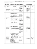
Страница 216: ...e height from the coolant level to the filling port NO YES 1 Inspecting the coolant system route Is any defect found Repair or replace the defective part After repair replacement perform the inspec tion again Go to step 2 2 Inspecting the coolant level Is the coolant level about 10 mm from the filling port Go to step 3 Add coolant See Adding coolant After adding coolant perform the inspection agai...

Страница 217: ...temperature sensor 3 Using the electrical tester measure the resistance between the terminals of coolant temperature sensor connector NO YES 3 Reading the DTC HINO DX SHTS03ZZZ0300141 Is any DTC other than P0A93 7A detected Perform troubleshooting for each of related DTC Go to step 4 4 Inspecting the coolant temperature sensor SHTS03ZZZ0300142 Measurement conditions Tester connections Standard val...

Страница 218: ...ition 4 Clear the malfunction history 5 Perform a test run for approximately 30 minutes 6 In Fault Information on the diagnosis tool screen check if P0A93 7A is detected NO YES 5 Inspecting the signal line of PCU wire harness lower side for short circuit Measurement conditions Tester connections Standard values Starter key LOCK Coolant tempera ture sensor con nector 2nd terminal Each signal line 1...

Страница 219: ... the filling port Coolant level is about 10 mm from the filling port Go to YES Coolant level is not about 10 mm from the filling port Go to NO Go to step 3 Add coolant See Adding coolant After adding coolant per form the inspection again 3 Reading the DTC HINO DX 1 Set the starter key to the LOCK position 2 Connect the diagnosis tool HINO DX to the vehicle 3 Set the starter key to the ON position ...

Страница 220: ... sensor connector inspect the signal line of PCU wire harness lower side for short circuit See Inspecting the PCU harness signal line for short circuit Measurement conditions Starter key LOCK Tester connections Coolant temperature sensor con nector 2nd terminal Each signal line Standard values 10 k or more Defect is found Go to YES Defect is not found Go to NO Replace the PCU wire har ness lower s...

Страница 221: ...mains at 12 4 mph or more for 30 seconds or more The square sum of HV battery current for 1800 seconds is 200 000 A2 or more 2 Judgement criteria The HV battery temperature remains less than 30 C 22 F for 10 seconds or more 3 Reset condition The HV battery temperature remains at 30 C 22 F or more for 10 seconds or more 4 Indication warning or system control regulation when the DTC is set MIL ON HV...

Страница 222: ... inverter line is detected NO YES 1 In Fault Information on the diagnosis tool screen check if any DTC related to the HV battery line is detected NO YES 1 Inspecting the inverter HINO DX SHTS03ZZZ0300144 Is any DTC related to the inverter line detected Perform troubleshooting for each of related DTC Go to step 2 2 Inspecting the HV battery ECU HINO DX SHTS03ZZZ0300145 Is any DTC related to the HV ...

Страница 223: ...INO DX SHTS03ZZZ0300146 Measurement conditions Tester connections Standard values Starter key ON HV battery mini mum temperature HV battery mini mum temperature 30 C 22 F or more Is the measured value within the range of standard value The inspection is completed An abnormally low temperature of HV bat tery may occur due to the outside tempera ture Replace the battery ECU ...

Страница 224: ... DX 1 In Fault Information on the diagnosis tool screen check if any DTC related to the HV bat tery line is detected DTC related to the HV battery line is detected Go to YES DTC related to the HV battery line is not detected Go to NO Perform trou bleshooting for each of related DTC Go to step 3 3 Inspecting the HV battery temperature HINO DX 1 Select Data Monitor on the diagnosis tool screen and m...

Страница 225: ...e is 10 V or more 2 Judgement criteria The HV battery cooling fan revolving number voltage remains more than 4 8 V for 1 second or more 3 Reset condition The HV battery cooling fan revolving number voltage remains at 4 8 V or less for 1 second or more 4 Indication warning or system control regulation when the DTC is set MIL ON HV warning light ON 5 Symptoms on the vehicle when the DTC is set Sympt...

Страница 226: ...ere is no abnormality 7 After inspection work Clear the recorded DTC Check that no DTC is detected after test driving the vehicle 8 Estimated failure factors Disconnection or short circuit of harness Improper connector connection or fitting Malfunction of HV battery cooling fan Malfunction of HV ECU ...

Страница 227: ...r side connector inspect the signal line of PCU wire harness lower side for short circuit See Inspecting the PCU harness signal line for short cir cuit NO YES 1 Reading the DTC HINO DX SHTS03ZZZ0300148 Is DTC P060B B2 detected Perform troubleshooting for each of related DTC Go to step 2 2 Inspecting the signal line of PCU wire harness lower side for short circuit Measurement conditions Tester conn...

Страница 228: ...er key to the LOCK position and wait for 1 minute 5 Set the starter key to the ON position 6 In Fault Information on the diagnosis tool screen check if P0BCA 68 is detected NO YES 3 Inspecting the signal line of PCU wire harness upper side for short circuit Measurement conditions Tester connections Standard values Starter key LOCK PCU harness 16P upper side con nector 12th terminal Each signal lin...

Страница 229: ...wire harness lower side for short circuit See Inspect ing the PCU harness signal line for short circuit Measurement conditions Starter key LOCK Tester connections PCU harness 16P lower side connector 12th terminal Each signal line Standard values 10 k or more Defect is found Go to YES Defect is not found Go to NO Replace the PCU wire har ness lower side Go to step 3 3 Inspecting the signal line of...

Страница 230: ...the LOCK position and wait for 1 minute 5 Set the starter key to the ON position 6 In Fault Information on the diagnosis tool screen check if P0BCA 68 is detected DTC P0BCA 68 is detected Go to YES DTC P0BCA 68 is not detected Go to NO Replace the HV ECU The inspec tion is com pleted P0BCA TC68 Abnormality in HV battery cooling fan revolving number signal High Inspection Procedure Step Action Desc...

Страница 231: ...trol supply voltage is 10 V or more The drive duty of HV water pump is 61 or less The drive duty of HV water pump is 40 or more The output of inverter start relay is ON The vehicle speed remains at 12 4 mph for 30 seconds or more The engine intake air temperature sensor shows no abnormality The engine intake air temperature is 10 C 14 F or more The HV system coolant temperature is 20 C 4 F or more...

Страница 232: ...mit The number of revolutions of the HV water pump is higher than or equal to the lower limit For upper and lower limits see below Lower limit When HV water pump drive duty is 40 1273 0 r min When HV water pump drive duty is 50 1806 0 r min When HV water pump drive duty is 61 2319 7 r min Upper limit When HV water pump drive duty is 40 2473 2 r min When HV water pump drive duty is 50 3206 0 r min ...

Страница 233: ...DTC is detected P314C 82 P314D 81 P324B 62 P324C 61 P0A06 7F P0A07 7E NO YES 1 Check the coolant system route radiator inverter and hose for any damage or water leakage NO YES 1 Reading the DTC HINO DX SHTS03ZZZ0300151 Is any DTC other than P0C73 80 detected Perform troubleshooting for each of related DTC Go to step 2 2 Inspecting the coolant system route Is any defect found Repair or replace the ...

Страница 234: ...t circuit See Inspecting the PCU harness signal line for short circuit NO YES 3 Inspecting the coolant level Is the coolant level about 10 mm from the filling port Go to step 4 Add coolant See Adding coolant After adding coolant perform the inspection again 4 Inspecting the signal line of PCU wire harness lower side for short circuit 1 Measurement conditions Tester connections Standard values Star...

Страница 235: ...the LOCK position and wait for 1 minute 6 Perform a test run For 1 minutes at the vehicle speed of 30 km h or more 7 Set the starter key to the ON position 8 In Fault Information on the diagnosis tool screen check if P0C73 80 is detected NO YES 5 Inspecting the signal line of PCU wire harness lower side for short circuit 2 Measurement conditions Tester connections Standard values Starter key LOCK ...

Страница 236: ...ective part After repair replacement perform the inspection again Go to step 3 3 Inspecting the coolant level Remove the radiator cap and check the height from the coolant level to the filling port Coolant level is about 10 mm from the filling port Go to YES Coolant level is not about 10 mm from the filling port Go to NO Go to step 4 Add coolant See Adding coolant After adding coolant per form the...

Страница 237: ...ol ing pump After replace ment go to step 6 6 Reproduction check HINO DX 1 Connect all the connectors that have been disconnected to restore the system 2 Set the starter key to the ON position 3 Clear the malfunction history 4 Perform a test run For 1 min utes at the vehicle speed of 30 km h or more 5 Set the starter key to the LOCK position and wait for 1 minute 6 Perform a test run For 1 min ute...

Страница 238: ...The control power supply voltage is 10 V or more The output of HV battery ECU start relay is ON 2 Judgement criteria The output of HV battery ECU start relay and the IG2 status of CAN data remain unmatched for 2 seconds or more 3 Reset condition The output of HV battery ECU start relay and the IG2 status of CAN data are matched 4 Indication warning or system control regulation when the DTC is set ...

Страница 239: ...function stops reducing the feeling of deceleration during deceleration 6 Pre inspection work Check the battery voltage to make sure that there is no abnormality 7 After inspection work Clear the recorded DTC Check that any DTC will not be detected after test driving the vehicle 8 Estimated failure factors Disconnection or short circuit of harness Improper connector connection or fitting Malfuncti...

Страница 240: ...et the starter key to the ON position 4 Using the electrical tester measure the voltage between the vehi cle side connector terminals of PCU harness 24P NO YES 1 Reading the DTC HINO DX SHTS03ZZZ0300154 Is DTC P33B1 64 or P33B2 63 detected Perform troubleshooting for each of related DTC Go to step 2 2 Inspecting the power supply of vehicle wire harness SHTS03ZZZ0300155 Measurement conditions Teste...

Страница 241: ...e 1st and 2nd terminals of HV battery start relay and measure the resistance between the 3rd and 5th terminals With voltage applied NO YES 3 Inspecting the HV battery start relay 3 5 1 2 SHTS03ZZZ0300156 Measurement conditions Tester connections Standard values Starter key LOCK HV battery start relay 3rd terminal 5th terminal Without voltage 10 k or more With voltage less than 1 Is the measured va...

Страница 242: ...r measure the voltage between the lower side connector terminals of PCU harness 16P NO YES 4 Inspecting the PCU wire harness lower side SHTS03ZZZ0300157 Measurement conditions Tester connections Standard values Starter key ON PCU harness 16P lower side con nector 14th terminal 16th terminal 9 V or more Is the measured value within the range of standard value Go to step 5 Replace the PCU wire harne...

Страница 243: ... measure the voltage between the bat tery ECU 26P connector terminals NO YES 5 Inspecting the PCU wire harness upper side SHTS03ZZZ0300158 Measurement conditions Tester connections Standard values Starter key ON Battery ECU 26P connector 2nd terminal 12th terminal 13th terminal 12th terminal 9 V or more Is the measured value within the range of standard value Replace the HV battery ECU Replace the...

Страница 244: ... 64 or P33B2 63 is not detected Go to NO Perform trou bleshooting for each of related DTC Go to step 2 2 Inspecting the power supply of vehicle wire harness 1 Set the starter key to the LOCK position 2 Disconnect the PCU harness 24P connector 3 Set the starter key to the ON position 4 Using the electrical tester mea sure the voltage between the vehicle side connector termi nals of PCU harness 24P ...

Страница 245: ...e mea sured value is not within the range of stan dard value Go to NO Go to step 4 Replace the HV battery start relay 4 Inspecting the PCU wire har ness lower side 1 Connect the HV battery start relay and PCU harness 24P connectors 2 Disconnect the PCU harness 16P connector 3 Set the starter key to the ON position 4 Using the electrical tester mea sure the voltage between the lower side connector ...

Страница 246: ...nector terminals Measurement conditions Starter key ON Tester connections Battery ECU 26P connector 2nd terminal 12th terminal 13th terminal 12th terminal Standard values 9 V or more The mea sured value is within the range of stan dard value Go to YES The mea sured value is not within the range of stan dard value Go to NO Replace the HV battery ECU Replace the PCU wire har ness upper side P3000 TC...

Страница 247: ...trol regulation when the DTC is set MIL OFF HV warning light ON 5 Symptoms on the vehicle when the DTC is set Symptoms on the vehicle due to backup control fail safe Symptoms on the vehicle due to malfunction The engine may become unable to start Note however that vehicles equipped with a starter will be started with the starter Idling stop may become unavailable The regeneration function stops wh...

Страница 248: ...N position and wait for 1 minute 4 In Fault Information on the diagnosis tool screen check if any of the following DTC is detected P3001 41 P3001 43 P3001 44 P3001 45 P3001 4B P3001 4C NO YES 1 Inspecting the HV battery ECU HINO DX SHTS03ZZZ0300159 Is any DTC related to the HV battery line detected Perform troubleshooting for each of related DTC If communication between the diagnosis tool and the ...

Страница 249: ...detected Go to NO Perform trou bleshooting for each of related DTC If communica tion between the diagnosis tool and the HV battery ECU is not available replace the HV battery ECU Go to step 2 2 Reproduction check HINO DX 1 Clear the malfunction history 2 Set the starter key to the LOCK position and wait for 1 minute 3 Set the starter key to the ON position and wait for 1 minute 4 In Fault Informat...

Страница 250: ...esult HV battery ECU CAN received data BTER2 1 abnormality in current detection line 3 Reset condition HV battery ECU CAN received data BTER0 0 HV battery ECU CAN received data BTER1 0 HV battery ECU CAN received data BTER2 0 4 Indication warning or system control regulation when the DTC is set MIL OFF HV warning light ON 5 Symptoms on the vehicle when the DTC is set Symptoms on the vehicle due to...

Страница 251: ...N position and wait for 1 minute 4 In Fault Information on the diagnosis tool screen check if any of the following DTC is detected P3001 41 P3001 43 P3001 44 P3001 45 P3001 4B P3001 4C NO YES 1 Inspecting the HV battery ECU HINO DX SHTS03ZZZ0300161 Is any DTC related to the HV battery line detected Perform troubleshooting for each of related DTC If communication between the diagnosis tool and the ...

Страница 252: ...detected Go to NO Perform trou bleshooting for each of related DTC If communica tion between the diagnosis tool and the HV battery ECU is not available replace the HV battery ECU Go to step 2 2 Reproduction check HINO DX 1 Clear the malfunction history 2 Set the starter key to the LOCK position and wait for 1 minute 3 Set the starter key to the ON position and wait for 1 minute 4 In Fault Informat...

Страница 253: ...lation when the DTC is set MIL OFF HV warning light ON 5 Symptoms on the vehicle when the DTC is set Symptoms on the vehicle due to backup control fail safe Symptoms on the vehicle due to malfunction The engine may become unable to start Note however that vehicles equipped with a starter will be started with the starter Idling stop may become unavailable The regeneration function stops which may r...

Страница 254: ...N position and wait for 1 minute 4 In Fault Information on the diagnosis tool screen check if any of the following DTC is detected P3001 41 P3001 43 P3001 44 P3001 45 P3001 4B P3001 4C NO YES 1 Inspecting the HV battery ECU HINO DX SHTS03ZZZ0300163 Is any DTC related to the HV battery line detected Perform troubleshooting for each of related DTC If communication between the diagnosis tool and the ...

Страница 255: ...detected Go to NO Perform trou bleshooting for each of related DTC If communica tion between the diagnosis tool and the HV battery ECU is not available replace the HV battery ECU Go to step 2 2 Reproduction check HINO DX 1 Clear the malfunction history 2 Set the starter key to the LOCK position and wait for 1 minute 3 Set the starter key to the ON position and wait for 1 minute 4 In Fault Informat...

Страница 256: ...em control regulation when the DTC is set MIL OFF HV warning light ON 5 Symptoms on the vehicle when the DTC is set Symptoms on the vehicle due to backup control fail safe Symptoms on the vehicle due to malfunction The engine may become unable to start Note however that vehicles equipped with a starter will be started with the starter Idling stop may become unavailable The regeneration function st...

Страница 257: ...N position and wait for 1 minute 4 In Fault Information on the diagnosis tool screen check if any of the following DTC is detected P3001 41 P3001 43 P3001 44 P3001 45 P3001 4B P3001 4C NO YES 1 Inspecting the HV battery ECU HINO DX SHTS03ZZZ0300165 Is any DTC related to the HV battery line detected Perform troubleshooting for each of related DTC If communication between the diagnosis tool and the ...

Страница 258: ...detected Go to NO Perform trou bleshooting for each of related DTC If communica tion between the diagnosis tool and the HV battery ECU is not available replace the HV battery ECU Go to step 2 2 Reproduction check HINO DX 1 Clear the malfunction history 2 Set the starter key to the LOCK position and wait for 1 minute 3 Set the starter key to the ON position and wait for 1 minute 4 In Fault Informat...

Страница 259: ... control regulation when the DTC is set MIL OFF HV warning light ON 5 Symptoms on the vehicle when the DTC is set Symptoms on the vehicle due to backup control fail safe Symptoms on the vehicle due to malfunction The engine may become unable to start Note however that vehicles equipped with a starter will be started with the starter Idling stop may become unavailable The regeneration function stop...

Страница 260: ...ng is detected P3001 46 P3001 47 P3001 4A NO YES 1 In Fault Information on the diagnosis tool screen check if any DTC related to the inverter line is detected NO YES 1 Reading the DTC HINO DX SHTS03ZZZ0300167 Is any DTC other than P3001 46 P3001 47 or P3001 4A detected Perform troubleshooting for each of related DTC Go to step 2 2 Inspecting the inverter HINO DX SHTS03ZZZ0300168 Is any DTC related...

Страница 261: ...up stop the vehicle Acceleration to 40 km h Deceleration Stop the vehicle 3 In Fault Information on the diagnosis tool screen check if DTC P3001 46 is detected NO YES 3 Inspecting the HV battery ECU HINO DX SHTS03ZZZ0300169 Is any DTC related to the HV battery line detected Perform troubleshooting for each of related DTC Go to step 4 4 Reproduction check HINO DX SHTS03ZZZ0300170 Is DTC P3001 46 de...

Страница 262: ...elated to the inverter line is detected DTC related to the inverter line is detected Go to YES DTC related to the inverter line is not detected Go to NO Perform trou bleshooting for each of related DTC Go to step 3 3 Inspecting the HV battery ECU HINO DX 1 In Fault Information on the diagnosis tool screen check if any DTC related to the HV bat tery line is detected DTC related to the HV battery li...

Страница 263: ...ol regulation when the DTC is set MIL OFF HV warning light ON 5 Symptoms on the vehicle when the DTC is set Symptoms on the vehicle due to backup control fail safe Symptoms on the vehicle due to malfunction The engine may become unable to start Note however that vehicles equipped with a starter will be started with the starter Idling stop may become unavailable The regeneration function stops whic...

Страница 264: ...ng is detected P3001 46 P3001 47 P3001 4A NO YES 1 In Fault Information on the diagnosis tool screen check if any DTC related to the inverter line is detected NO YES 1 Reading the DTC HINO DX SHTS03ZZZ0300171 Is any DTC other than P3001 46 P3001 47 or P3001 4A detected Perform troubleshooting for each of related DTC Go to step 2 2 Inspecting the inverter HINO DX SHTS03ZZZ0300172 Is any DTC related...

Страница 265: ...up stop the vehicle Acceleration to 40 km h Deceleration Stop the vehicle 3 In Fault Information on the diagnosis tool screen check if DTC P3001 47 is detected NO YES 3 Inspecting the HV battery ECU HINO DX SHTS03ZZZ0300173 Is any DTC related to the HV battery line detected Perform troubleshooting for each of related DTC Go to step 4 4 Reproduction check HINO DX SHTS03ZZZ0300174 Is DTC P3001 47 de...

Страница 266: ...elated to the inverter line is detected DTC related to the inverter line is detected Go to YES DTC related to the inverter line is not detected Go to NO Perform trou bleshooting for each of related DTC Go to step 3 3 Inspecting the HV battery ECU HINO DX 1 In Fault Information on the diagnosis tool screen check if any DTC related to the HV bat tery line is detected DTC related to the HV battery li...

Страница 267: ...l regulation when the DTC is set MIL OFF HV warning light ON 5 Symptoms on the vehicle when the DTC is set Symptoms on the vehicle due to backup control fail safe Symptoms on the vehicle due to malfunction The engine may become unable to start Note however that vehicles equipped with a starter will be started with the starter Idling stop may become unavailable The regeneration function stops which...

Страница 268: ...ng is detected P3001 46 P3001 47 P3001 4A NO YES 1 In Fault Information on the diagnosis tool screen check if any DTC related to the inverter line is detected NO YES 1 Reading the DTC HINO DX SHTS03ZZZ0300175 Is any DTC other than P3001 46 P3001 47 or P3001 4A detected Perform troubleshooting for each of related DTC Go to step 2 2 Inspecting the inverter HINO DX SHTS03ZZZ0300176 Is any DTC related...

Страница 269: ...up stop the vehicle Acceleration to 40 km h Deceleration Stop the vehicle 3 In Fault Information on the diagnosis tool screen check if DTC P3001 4A is detected NO YES 3 Inspecting the HV battery ECU HINO DX SHTS03ZZZ0300177 Is any DTC related to the HV battery line detected Perform troubleshooting for each of related DTC Go to step 4 4 Reproduction check HINO DX SHTS03ZZZ0300178 Is DTC P3001 4A de...

Страница 270: ...elated to the inverter line is detected DTC related to the inverter line is detected Go to YES DTC related to the inverter line is not detected Go to NO Perform trou bleshooting for each of related DTC Go to step 3 3 Inspecting the HV battery ECU HINO DX 1 In Fault Information on the diagnosis tool screen check if any DTC related to the HV bat tery line is detected DTC related to the HV battery li...

Страница 271: ... control regulation when the DTC is set MIL OFF HV warning light ON 5 Symptoms on the vehicle when the DTC is set Symptoms on the vehicle due to backup control fail safe Symptoms on the vehicle due to malfunction The engine may become unable to start Note however that vehicles equipped with a starter will be started with the starter Idling stop may become unavailable The regeneration function stop...

Страница 272: ...N position and wait for 1 minute 4 In Fault Information on the diagnosis tool screen check if any of the following DTC is detected P3001 41 P3001 43 P3001 44 P3001 45 P3001 4B P3001 4C NO YES 1 Inspecting the HV battery ECU HINO DX SHTS03ZZZ0300179 Is any DTC related to the HV battery line detected Perform troubleshooting for each of related DTC If communication between the diagnosis tool and the ...

Страница 273: ...detected Go to NO Perform trou bleshooting for each of related DTC If communica tion between the diagnosis tool and the HV battery ECU is not available replace the HV battery ECU Go to step 2 2 Reproduction check HINO DX 1 Clear the malfunction history 2 Set the starter key to the LOCK position and wait for 1 minute 3 Set the starter key to the ON position and wait for 1 minute 4 In Fault Informat...

Страница 274: ...ing or system control regulation when the DTC is set MIL OFF HV warning light ON 5 Symptoms on the vehicle when the DTC is set Symptoms on the vehicle due to backup control fail safe Symptoms on the vehicle due to malfunction The engine may become unable to start Note however that vehicles equipped with a starter will be started with the starter Idling stop may become unavailable The regeneration ...

Страница 275: ...N position and wait for 1 minute 4 In Fault Information on the diagnosis tool screen check if any of the following DTC is detected P3001 41 P3001 43 P3001 44 P3001 45 P3001 4B P3001 4C NO YES 1 Inspecting the HV battery ECU HINO DX SHTS03ZZZ0300181 Is any DTC related to the HV battery line detected Perform troubleshooting for each of related DTC If communication between the diagnosis tool and the ...

Страница 276: ...detected Go to NO Perform trou bleshooting for each of related DTC If communica tion between the diagnosis tool and the HV battery ECU is not available replace the HV battery ECU Go to step 2 2 Reproduction check HINO DX 1 Clear the malfunction history 2 Set the starter key to the LOCK position and wait for 1 minute 3 Set the starter key to the ON position and wait for 1 minute 4 In Fault Informat...

Страница 277: ...condition After return to normal 4 Indication warning or system control regulation when the DTC is set MIL OFF HV warning light OFF 5 Symptoms on the vehicle when the DTC is set Symptoms on the vehicle due to backup control fail safe Symptoms on the vehicle due to malfunction 6 Pre inspection work Check the battery voltage to make sure that there is no abnormality 17 U P N W V 18 19 15 16 13 14 24...

Страница 278: ...Clear the recorded DTC Check that no DTC is detected after test driving the vehicle 8 Estimated failure factors Disconnection or short circuit of harness Improper connector connection or fitting Malfunction of high voltage circuit Malfunction of HV battery ...

Страница 279: ...ectrical tester measure the insulation resistance between the terminals of high voltage J B in the battery pack and the ground NO YES 1 Preparation for inspection Is the inspection preparation completed Go to step 2 Perform the inspection preparation again 2 Inspection of HV battery BATT IN 4 BATT IN 3 SHTS03ZZZ0300184 Measurement conditions Tester connections Standard values Starter key LOCK High...

Страница 280: ...d the ground NO YES 3 Inspecting the service plug 1 2 1 SHTS03ZZZ0300185 Measurement conditions Tester connections Standard values Starter key LOCK Frame wire 1st terminal GND 2nd terminal GND 10 M or more Is the measured value within the range of standard value Go to step 4 Replacing the frame wire with the service plug socket 4 Inspecting the service plug 2 2 1 SHTS03ZZZ0300186 Measurement condi...

Страница 281: ...ry pack and the ground NO YES 5 Inspecting the insulation resistance of high voltage J B in the battery pack BATT OUT 6 BATT IN 4 BATT OUT 5 BATT IN 3 SHTS03ZZZ0300187 Measurement conditions Tester connections Standard values Starter key LOCK High voltage J B in the battery pack 3rd terminal GND 4th terminal GND 5th terminal GND 6th terminal GND 10 M or more Is the measured value within the range ...

Страница 282: ...und NO YES 6 Inspecting the insulation resistance of frame wire to the high voltage J B 9 10 SHTS03ZZZ0300188 Measurement conditions Tester connections Standard values Starter key LOCK Frame wire 9th terminal GND 10th terminal GND 10 M or more Is the measured value within the range of standard value Go to step 7 Replace the frame wire 7 Inspecting the insulation resistance of high voltage J B in t...

Страница 283: ...als of frame wire and the ground NO YES 8 Inspecting the insulation resistance of frame wire between the high voltage J B in the ECU box and the inverter 15 16 SHTS03ZZZ0300190 Measurement conditions Tester connections Standard values Starter key LOCK Frame wire 15th terminal GND 16th terminal GND 10 M or more Is the measured value within the range of standard value Go to step 9 Replace the frame ...

Страница 284: ...of inverter and the ground NO YES 9 Inspecting the insulation resistance of inverter 19 17 18 15 16 MEGGER VEHICLE GND SHTS03ZZZ0300191 Measurement conditions Tester connections Standard values Starter key LOCK Inverter 15th terminal GND 16th terminal GND 17th terminal GND 18th terminal GND 19th terminal GND 3 M or more Is the measured value within the range of standard value Go to step 10 Replace...

Страница 285: ... Inspecting the insulation resistance of frame wire between the inverter and the relay terminal block U V W 20 21 22 SHTS03ZZZ0300192 Measurement conditions Tester connections Standard values Starter key LOCK Frame wire 20th terminal GND 21st terminal GND 22nd terminal GND 10 M or more Is the measured value within the range of standard value Go to step 11 For vehicles with no relay terminal block ...

Страница 286: ... block Measurement conditions Tester connections Standard values Starter key LOCK Relay terminal block 20th terminal GND 21st terminal GND 22nd terminal GND 10 M or more Is the measured value within the range of standard value Go to step 12 Replace the relay terminal block 12 Inspecting the insulation resistance of frame wire between the inverter and the HV motor U V W 23 24 25 SHTS03ZZZ0300193 Me...

Страница 287: ...lfunction history 6 Perform a test run For 30 minutes or more 7 In Fault Information on the diagnosis tool screen check if P3009 49 is detected NO YES 13 Inspecting the insulation resistance of HV motor 25 24 23 SHTS03ZZZ0300194 Measurement conditions Tester connections Standard values Starter key LOCK HV motor 23rd terminal GND 24th terminal GND 25th terminal GND 5 M or more Is the measured value...

Страница 288: ...ttery pack and the ground Measurement conditions Starter key LOCK Tester connections High voltage J B in battery pack BATT IN 3 terminal GND BATT IN 4 terminal GND Standard values 10 M or more The mea sured value is within the range of stan dard value Go to YES The mea sured value is not within the range of stan dard value Go to NO Go to step 5 Go to step 3 3 Inspecting the service plug 1 1 Discon...

Страница 289: ...conditions Starter key LOCK Tester connections High voltage J B in the battery pack 3rd terminal GND 4th terminal GND 5th terminal GND 6th terminal GND Standard values 10 M or more The mea sured value is within the range of stan dard value Go to YES The mea sured value is not within the range of stan dard value Go to NO Go to step 6 Replace the high voltage J B in the bat tery pack 6 Inspecting th...

Страница 290: ... tester mea sure the insulation resistance between the terminals of frame wire and the ground Measurement conditions Starter key LOCK Tester connections Frame wire 15th terminal GND 16th terminal GND Standard values 10 M or more The mea sured value is within the range of stan dard value Go to YES The mea sured value is not within the range of stan dard value Go to NO Go to step 9 Replace the frame...

Страница 291: ...ls and the ground Measurement conditions Starter key LOCK Tester connections Relay terminal block 20th terminal GND 21st terminal GND 22nd terminal GND Standard values 10 M or more The mea sured value is within the range of stan dard value Go to YES The mea sured value is not within the range of stan dard value Go to NO Go to step 12 Replace the relay terminal block 12 Inspecting the insulation re...

Страница 292: ...O Go to step 14 Replace the HV motor 14 Reproduction check HINO DX 1 Connect all the cables and con nectors that have been discon nected to restore the system 2 Set the starter key to the LOCK position 3 Connect the diagnosis tool HINO DX to the vehicle 4 Set the starter key to the ON position 5 Clear the malfunction history 6 Perform a test run For 30 min utes or more 7 In Fault Information on th...

Страница 293: ...e number of revolutions of the HV radiator fan remains less than 2500 r min for 10 seconds or more 3 Reset condition The number of revolutions of the HV radiator fan remains 2500 r min or more for 10 seconds or more 4 Indication warning or system control regulation when the DTC is set MIL ON HV warning light ON 5 Symptoms on the vehicle when the DTC is set Symptoms on the vehicle due to backup con...

Страница 294: ...ork Clear the recorded DTC Check that no DTC is detected after test driving the vehicle 8 Estimated failure factors Disconnection or short circuit of harness Improper connector connection or fitting Malfunction of HV radiator fan Malfunction of HV ECU ...
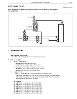
Страница 295: ...24B 62 P324C 61 NO YES 1 Check that the HV radiator and the inverter cooling radiator fan have no damage or clogging NO YES 1 Set the starter key to the ON position 2 Check that the inverter cooling radiator fan is running NO YES 1 Reading the DTC HINO DX SHTS03ZZZ0300197 Is DTC P324B 62 or P324C 61 detected Perform troubleshooting for each of related DTC Go to step 2 2 Inspecting the HV radiator ...

Страница 296: ...erminal of PCU harness 24P vehicle side connector and the ground NO YES 4 Inspecting the voltage of vehicle wire harness VEHICLE GND SHTS03ZZZ0300198 Measurement conditions Tester connections Standard values Starter key ON PCU harness 24P vehicle side con nector 3rd terminal GND 9 V or more Is the measured value within the range of standard value Go to step 5 Inspect the power supply circuit PCI B...

Страница 297: ...the 1st and 2nd terminals of inverter start relay and measure the resistance between the 3rd and 5th terminals With voltage applied NO YES 5 Inspecting the inverter start relay 3 5 1 2 SHTS03ZZZ0300199 Measurement conditions Tester connections Standard values Starter key LOCK Inverter start relay 3rd terminal 5th terminal Without voltage 10 k or more With voltage less than 1 Is the measured value ...

Страница 298: ...r measure the voltage between the con nector terminals of inverter cooling radiator fan NO YES 6 Inspecting the voltage of PCU wire harness lower side SHTS03ZZZ0300200 Measurement conditions Tester connections Standard values Starter key ON Inverter cooling radiator fan con nector 1st terminal 2nd terminal 9 V or more Is the measured value within the range of standard value Go to step 7 Replace th...

Страница 299: ...ower side SHTS03ZZZ0300201 Measurement conditions Tester connections Standard values Starter key LOCK Inverter cooling radiator fan con nector to HV ECU1 connector 3rd terminal 25th terminal Less than 1 Is the measured value within the range of standard value Go to step 8 Replace the PCU wire harness lower side 8 Inspecting the PCU wire harness lower side for short circuit VEHICLE GND SHTS03ZZZ030...

Страница 300: ...and wait for 1 minute 7 Set the starter key to the LOCK position and wait for 1 minute 8 Set the starter key to the ON position and wait for 1 minute 9 In Fault Information on the diagnosis tool screen check if P3128 7D is detected NO YES 9 Inspecting the signal line of PCU wire harness lower side for short circuit Measurement conditions Tester connections Standard values Starter key LOCK Inverter...

Страница 301: ... is found Go to YES Defect is not found Go to NO Repair clean or replace the defective part Go to step 3 3 Checking the inverter cool ing radiator fan 1 Set the starter key to the ON position 2 Check that the inverter cooling radiator fan is running Inverter cool ing radiator fan is running Go to YES Inverter cool ing radiator fan is not running Go to NO Go to step 7 Go to step 4 4 Inspecting the ...

Страница 302: ...ot within the range of stan dard value Go to NO Go to step 6 Replace the inverter start relay 6 Inspecting the voltage of PCU wire har ness lower side 1 Connect the PCU harness 24P connector and the inverter start relay 2 Disconnect the connector of inverter cooling radiator fan 3 Set the starter key to the ON position 4 Using the electrical tester mea sure the voltage between the connector termin...

Страница 303: ...connector and the ground Measurement conditions Starter key LOCK Tester connections Inverter cooling radiator fan con nector 3rd terminal GND Standard values 10 k or more The mea sured value is within the range of stan dard value Go to YES The mea sured value is not within the range of stan dard value Go to NO Go to step 9 Replace the PCU wire har ness lower side 9 Inspecting the signal line of PC...

Страница 304: ...arter key to the ON position and wait for 1 minute 7 Set the starter key to the LOCK position and wait for 1 minute 8 Set the starter key to the ON position and wait for 1 minute 9 In Fault Information on the diagnosis tool screen check if P3128 7D is detected DTC P3128 7D is detected Go to YES DTC P3128 7D is not detected Go to NO Replace the HV ECU The inspec tion is com pleted P3128 TC7D Abnorm...

Страница 305: ...teria The number of revolutions of the HV radiator fan remains less than 4500 r min for 10 seconds or more 3 Reset condition The number of revolutions of the HV radiator fan remains 4500 r min or more for 10 seconds 4 Indication warning or system control regulation when the DTC is set MIL ON HV warning light ON 5 Symptoms on the vehicle when the DTC is set Symptoms on the vehicle due to backup con...

Страница 306: ...ork Clear the recorded DTC Check that no DTC is detected after test driving the vehicle 8 Estimated failure factors Disconnection or short circuit of harness Improper connector connection or fitting Malfunction of HV radiator fan Malfunction of HV ECU ...

Страница 307: ...or short circuit See Inspecting the PCU harness signal line for short cir cuit NO YES 1 Inspecting the inverter cooling radiator fan Is any defect found Replace the inverter cooling radiator fan Go to step 2 2 Inspecting the signal line of PCU wire harness lower side for short circuit Measurement conditions Tester connections Standard values Starter key LOCK Inverter cooling radiator fan con necto...

Страница 308: ...position 5 Clear the malfunction history 6 Set the starter key to the ON position and wait for 1 minute 7 Set the starter key to the LOCK position and wait for 1 minute 8 Set the starter key to the ON position and wait for 1 minute 9 In Fault Information on the diagnosis tool screen check if P3129 7C is detected NO YES 3 Reproduction check HINO DX SHTS03ZZZ0300205 Is DTC P3129 7C detected Replace ...

Страница 309: ...ircuit Measurement conditions Starter key LOCK Tester connections Inverter cooling radiator fan con nector 3rd terminal Each signal line Standard values 10 k or more Defect is found Go to YES Defect is not found Go to NO Replace the PCU wire har ness lower side Replace the inverter cool ing radiator fan After replace ment go to step 3 3 Reproduction check HINO DX 1 Connect all the connectors that ...

Страница 310: ...re met continuously for 1 second or more The HV water pump revolution number signal is 0 Hz The HV water pump revolution number signal is OFF 3 Reset condition The HV water pump revolution number signal remains higher than 1 Hz for 5 seconds or more 4 Indication warning or system control regulation when the DTC is set MIL ON HV warning light ON 5 Symptoms on the vehicle when the DTC is set Symptom...

Страница 311: ...work Clear the recorded DTC Check that no DTC is detected after test driving the vehicle 8 Estimated failure factors Disconnection or short circuit of harness Improper contact or fitting of connector Malfunction of HV water pump Malfunction of HV ECU ...

Страница 312: ... NO YES 1 Inspecting the PCU wire harness lower side for short circuit VEHICLE GND SHTS03ZZZ0300207 Measurement conditions Tester connections Standard values Starter key LOCK Inverter cooling pump connector 2nd terminal GND 10 k or more Is the measured value within the range of standard value Go to step 2 Replace the PCU wire harness lower side 2 Inspecting the signal line of PCU wire harness lowe...

Страница 313: ...e vehicle 3 Set the starter key to the ON position 4 Clear the malfunction history 5 Set the starter key to the ON position and wait for 1 minute 6 In Fault Information on the diagnosis tool screen check if P314C 82 is detected NO YES 3 Reproduction check HINO DX SHTS03ZZZ0300208 Is DTC P314C 82 detected Replace the HV ECU The inspection is completed ...

Страница 314: ...ne of PCU wire har ness lower side for short circuit 1 For the 2nd terminal of inverter cooling pump connector inspect the signal line of PCU wire harness lower side for short circuit See Inspecting the PCU harness signal line for short circuit Measurement conditions Starter key LOCK Tester connections Inverter cooling pump connector 2nd terminal Each signal line Standard values 10 k or more Defec...

Страница 315: ...e met continuously for 1 second or more The HV water pump revolution number signal is 0 Hz The HV water pump revolution number signal is ON 3 Reset condition The HV water pump revolution number signal remains higher than 1 Hz for 5 seconds or more 4 Indication warning or system control regulation when the DTC is set MIL ON HV warning light ON 5 Symptoms on the vehicle when the DTC is set Symptoms ...

Страница 316: ...work Clear the recorded DTC Check that no DTC is detected after test driving the vehicle 8 Estimated failure factors Disconnection or short circuit of harness Improper contact or fitting of connector Malfunction of HV water pump Malfunction of HV ECU ...

Страница 317: ...for any damage or water leakage NO YES 1 Remove the radiator cap and check the height from the coolant level to the filling port NO YES 1 Reading the DTC HINO DX SHTS03ZZZ0300210 Is DTC P324B 62 or P324C 61 detected Perform troubleshooting for each of related DTC Go to step 2 2 Inspecting the coolant system route Is any defect found Repair or replace the defective part Go to step 3 3 Inspecting th...

Страница 318: ... Checking the activation of inverter cooling pump HINO DX SHTS03ZZZ0300211 Measurement conditions Measured item Standard values Starter key ON HV water pump drive duty value Activation of water pump Is the activation of water pump confirmed Go to step 8 Go to step 5 5 Inspecting the vehicle wire harness VEHICLE GND SHTS03ZZZ0300212 Measurement conditions Tester connections Standard values Starter ...

Страница 319: ... the 1st and 2nd terminals of inverter start relay and measure the resistance between the 3rd and 5th terminals With voltage applied NO YES 6 Inspecting the inverter start relay 3 5 1 2 SHTS03ZZZ0300213 Measurement conditions Tester connections Standard values Starter key ON Inverter start relay 3rd terminal 5th terminal Without voltage 10 k or more With voltage less than 1 Is the measured value w...

Страница 320: ...ter measure the voltage between the con nector terminals of inverter cooling pump NO YES 7 Inspecting the voltage of PCU wire harness lower side SHTS03ZZZ0300214 Measurement conditions Tester connections Standard values Starter key ON Inverter cooling pump connector 1st terminal 4th terminal 9 V or more Is the measured value within the range of standard value Go to step 8 Replace the PCU wire harn...

Страница 321: ...of PCU wire harness lower side SHTS03ZZZ0300215 Measurement conditions Tester connections Standard values Starter key LOCK Inverter cooling pump connector HV ECU1 connec tor 2nd terminal 26th terminal Less than 1 Is the measured value within the range of standard value Go to step 9 Replace the PCU wire harness lower side 9 Inspecting the signal line of PCU wire harness lower side for short circuit...

Страница 322: ...r key to the ON position 3 Clear the malfunction history 4 Set the starter key to the ON position and wait for 1 minute 5 In Fault Information on the diagnosis tool screen check if P314D 81 is detected NO YES 10 Reproduction check HINO DX SHTS03ZZZ0300216 Is DTC P314D 81 detected Replace the HV ECU The inspection is completed ...

Страница 323: ... is found Go to YES Defect is not found Go to NO Repair or replace the defective part Go to step 3 3 Inspecting the coolant level 1 Remove the radiator cap and check the height from the cool ant level to the filling port Coolant level is about 10 mm from the filling port Go to YES Coolant level is not about 10 mm from the filling port Go to NO Go to step 4 Add coolant See Adding coolant After addi...

Страница 324: ...e LOCK position 2 Remove the inverter start relay 3 Using the electrical tester mea sure the resistance between the 3rd and 5th terminals of inverter start relay With no voltage applied 4 Apply the voltage of 12 V between the 1st and 2nd termi nals of inverter start relay and measure the resistance between the 3rd and 5th termi nals With voltage applied Measurement conditions Starter key ON Tester...

Страница 325: ...or and the HV ECU1 con nector terminal Measurement conditions Starter key LOCK Tester connections Inverter cooling pump connector HV ECU1 connector 2nd terminal 26th terminal Standard values Less than 1 The mea sured value is within the range of stan dard value Go to YES The mea sured value is not within the range of stan dard value Go to NO Go to step 9 Replace the PCU wire har ness lower side 9 ...

Страница 326: ... 4 Set the starter key to the ON position and wait for 1 minute 5 In Fault Information on the diagnosis tool screen check if P314D 81 is detected DTC P314D 81 is detected Go to YES DTC P314D 81 is not detected Go to NO Replace the HV ECU The inspec tion is com pleted P314D TC81 Abnormality in HV water pump revolution number signal High Inspection Procedure Step Action Description Judgement Check Y...

Страница 327: ...usly for 0 1 second or more The output of inverter start relay is ON The feedback signal of inverter start relay is OFF 3 Reset condition The following conditions are met continuously for 0 1 second or more The output of inverter start relay is ON The feedback signal of inverter start relay is ON Once the abnormality is confirmed after the HV ECU is actuated next 4 Indication warning or system con...

Страница 328: ...dling stop is not available The regeneration function stops which may reduce the feeling of deceleration during deceleration 6 Pre inspection work Check the battery voltage to make sure that there is no abnormality 7 After inspection work Clear the recorded DTC Check that no DTC is detected after test driving the vehicle 8 Estimated failure factors Disconnection or short circuit of harness Imprope...

Страница 329: ...1 Inspecting the inverter start relay 3 5 1 2 SHTS03ZZZ0300218 Measurement conditions Tester connections Standard values Starter key LOCK Inverter start relay relay side 1st terminal 2nd terminal 95 125 Is the measured value within the range of standard value Go to step 2 Replace the inverter start relay 2 Inspecting the PCU wire harness lower side for short circuit VEHICLE GND SHTS03ZZZ0300219 Me...

Страница 330: ...See Inspecting the PCU harness signal line for short cir cuit NO YES 3 Inspecting the signal line of PCU wire harness lower side for short circuit Measurement conditions Tester connections Standard values Starter key LOCK Inverter start relay connector 1st terminal Each signal line 10 k or more Is any defect found Replace the PCU wire harness lower side Replace the HV ECU ...

Страница 331: ... and inverter connectors 2 Using the electrical tester mea sure the resistance between the inverter start relay connec tor relay block and the ground Measurement conditions Starter key LOCK Tester connections Inverter start relay connector 1st terminal GND Standard values 10 k or more The mea sured value is within the range of stan dard value Go to YES The mea sured value is not within the range o...

Страница 332: ...ons are met continuously for 0 1 second or more The output of inverter start relay is OFF The feedback signal of inverter start relay is ON 3 Reset condition The following conditions are met continuously for 0 1 second or more The output of inverter start relay is OFF The feedback signal of inverter start relay is OFF Once the abnormality is confirmed after the HV ECU is actuated next 4 Indication...

Страница 333: ...dling stop is not available The regeneration function stops which may reduce the feeling of deceleration during deceleration 6 Pre inspection work Check the battery voltage to make sure that there is no abnormality 7 After inspection work Clear the recorded DTC Check that no DTC is detected after test driving the vehicle 8 Estimated failure factors Disconnection or short circuit of harness Imprope...

Страница 334: ...ctrical tester measure the resistance between the inverter start relay terminals NO YES 1 Inspecting the inverter start relay 3 5 1 2 SHTS03ZZZ0300221 Measurement conditions Tester connections Standard values Inverter start relay relay side 1st terminal 2nd terminal 95 125 Is the measured value within the range of standard value Go to step 2 Replace the inverter start relay ...

Страница 335: ... the ground NO YES 2 Inspecting the continuity of PCU wire harness lower side VEHICLE GND SHTS03ZZZ0300222 Measurement conditions Tester connections Standard values Starter key LOCK Inverter start relay connector HV ECU2 connector 1st terminal 1st terminal Inverter start relay connector 2nd terminal GND Less than 1 Is the measured value within the range of standard value Go to step 3 Replace the P...

Страница 336: ...See Inspecting the PCU harness signal line for short cir cuit NO YES 3 Inspecting the signal line of PCU wire harness lower side for short circuit Measurement conditions Tester connections Standard values Starter key LOCK Inverter start relay connector 1st terminal Each signal line 10 k or more Is any defect found Replace the PCU wire harness lower side Replace the HV ECU ...

Страница 337: ...the resistance from the inverter start relay connector relay block to the HV ECU2 connector terminal and to the ground Measurement conditions Starter key LOCK Tester connections Inverter start relay connector HV ECU2 connector 1st terminal 1st terminal Inverter start relay connector 2nd terminal GND Standard values Less than 1 The mea sured value is within the range of stan dard value Go to YES Th...

Страница 338: ...s are met continuously for 0 1 second or more The output of HV battery ECU start relay is ON The feedback signal of HV battery ECU start relay is OFF 3 Reset condition The following conditions are met continuously for 0 1 second or more The output of HV battery ECU start relay is ON The feedback signal of HV battery ECU start relay is ON Once the abnormality is confirmed after the HV ECU is actuat...

Страница 339: ...stops which may reduce the feeling of deceleration during deceleration 6 Pre inspection work Check the battery voltage to make sure that there is no abnormality 7 After inspection work Clear the recorded DTC Check that any DTC is not detected after test driving the vehicle 8 Estimated failure factors Disconnection or short circuit of harness Improper connector connection or fitting Malfunction of ...

Страница 340: ...V battery start relay 3 5 1 2 SHTS03ZZZ0300224 Measurement conditions Tester connections Standard values HV battery start relay relay side 1st terminal 2nd terminal 95 125 Is the measured value within the range of standard value Go to step 2 Replace the HV battery start relay 2 Inspecting the PCU wire harness lower side for short circuit VEHICLE GND SHTS03ZZZ0300225 Measurement conditions Tester c...

Страница 341: ...for short circuit See Inspecting the PCU harness signal line for short circuit NO YES 3 Inspecting the signal line of PCU wire harness lower side for short circuit Measurement conditions Tester connections Standard values Starter key LOCK HV battery start relay connector 1st terminal Each signal line 10 k or more Is any defect found Replace the PCU wire harness lower side Replace the HV ECU ...

Страница 342: ...ester mea sure the resistance between the HV battery start relay con nector relay block and the ground Measurement conditions Starter key LOCK Tester connections HV battery start relay connector 1st terminal Ground Standard values 10 k or more The mea sured value is within the range of stan dard value Go to YES The mea sured value is not within the range of stan dard value Go to NO Go to step 3 Re...

Страница 343: ...following conditions are met continuously for 0 1 second or more The output of HV battery ECU start relay is OFF The feedback signal of HV battery ECU start relay is ON 3 Reset condition The following conditions are met continuously for 0 1 second or more The output of HV battery ECU start relay is OFF The feedback signal of HV battery ECU start relay is OFF Once the abnormality is confirmed after...

Страница 344: ...n stops which may reduce the feeling of deceleration during deceleration 6 Pre inspection work Check the battery voltage to make sure that there is no abnormality 7 After inspection work Clear the recorded DTC Check that no DTC is detected after test driving the vehicle 8 Estimated failure factors Disconnection or short circuit of harness Improper connector connection or fitting Malfunction of HV ...

Страница 345: ...ical tester measure the resistance between the HV battery start relay terminals NO YES 1 Inspecting the HV battery start relay 3 5 1 2 SHTS03ZZZ0300227 Measurement conditions Tester connections Standard values HV battery start relay relay side 1st terminal 2nd terminal 95 125 Is the measured value within the range of standard value Go to step 2 Replace the HV battery start relay ...

Страница 346: ...und NO YES 2 Inspecting the continuity of PCU wire harness lower side VEHICLE GND SHTS03ZZZ0300228 Measurement conditions Tester connections Standard values Starter key LOCK HV battery start relay connector HV ECU2 connec tor 1st terminal 2nd terminal HV battery start relay connector 2nd terminal GND Less than 1 Is the measured value within the range of standard value Go to step 3 Replace the PCU ...

Страница 347: ...See Inspecting the PCU harness signal line for short circuit NO YES 3 Inspecting the signal line of PCU wire harness lower side for short circuit Measurement conditions Tester connections Standard values Starter key LOCK HV battery start relay connector 1st terminal Each signal line 10 k or more Is any defect found Replace the PCU wire harness lower side Replace the HV ECU ...

Страница 348: ... resistance from the HV battery start relay connector relay block to the HV ECU2 connector terminal and to the ground Measurement conditions Starter key LOCK Tester connections HV battery start relay connector HV ECU2 connector 1st terminal 2nd terminal HV battery start relay connector 2nd terminal GND Standard values Less than 1 The mea sured value is within the range of stan dard value Go to YES...

Страница 349: ...ore in total If normal time continues for 5 seconds the accumulated time shall be reset 3 Reset condition A state in which no control CAN bus off is detected continues for 0 5 second or more Once the abnormality is confirmed the following conditions are included HV ECU runs within 0 5 second 4 Indication warning or system control regulation when the DTC is set MIL ON HV warning light ON ABS ECU CA...

Страница 350: ...reduce the feeling of deceleration during deceleration The CHG AST ECO and SOC lamp go off 6 Pre inspection work Check the battery voltage to make sure that there is no abnormality 7 After inspection work Clear the recorded DTC Check that no DTC is detected after test driving the vehicle 8 Estimated failure factors Disconnection or short circuit of harness Improper connector connection or fitting ...

Страница 351: ...U and inverter 5 Set the starter key to the LOCK position and wait for approxi mately 1 minute 6 Set the starter key to the ON position 7 In Fault Information on the diagnosis tool screen check if U0073 11 is detected NO YES 1 Implementation of common inspection items Is any defect found Repair or replace the malfunctioning part detected by the common inspection items Go to step 2 2 Reproduction c...

Страница 352: ...he diagnosis tool screen check if DTC U0073 91 is detected in the inverter NO YES 3 Inspecting the inverter HINO DX SHTS03ZZZ0300231 Is DTC U0073 91 detected Refer to the CONTROL CAN COMMUNICA TION LINE HYBRID in the chapter CON TROL SYSTEM Replace the HV ECU ...

Страница 353: ... to the vehicle 3 Set the starter key to the ON position 4 Clear the malfunction history of the HV ECU and inverter 5 Set the starter key to the LOCK position and wait for approximately 1 minute 6 Set the starter key to the ON position 7 In Fault Information on the diagnosis tool screen check if U0073 11 is detected DTC U0073 11 is detected Go to YES DTC U0073 11 is not detected Go to NO Go to ste...

Страница 354: ... 3 Reset condition A state in which no DIAG CAN bus off is detected continues for 0 5 second or more Once the abnormality is confirmed the following conditions are included HV ECU runs within 0 5 second 9 8 CANN VCS ECU Engine ECU CANP 5 4 L H L H L H L H CANL CANH 4 3 16 5 17 6 15 14 J C CAN 2 Telematics information 17 6 2 13 4 15 J C CAN1 22P Diagnosis connector DLC ATM ECU Clutch ECU CAN H CAN ...

Страница 355: ...ction becomes inoperative The regeneration function stops which may reduce the feeling of deceleration during deceleration 6 Pre inspection work Check the battery voltage to make sure that there is no abnormality 7 After inspection work Clear the recorded DTC Check that no DTC is detected after test driving the vehicle 8 Estimated failure factors Disconnection or short circuit of harness Improper ...

Страница 356: ...sition and wait for approxi mately 1 minute 6 Set the starter key to the ON position 7 In Fault Information on the diagnosis tool screen check if U0074 16 is detected NO YES 1 Implementation of common inspection items Is any defect found Repair or replace the malfunctioning part detected by the common inspection items Go to step 2 2 Reproduction check HINO DX SHTS03ZZZ0300233 Is DTC U0074 16 detec...

Страница 357: ...on items Go to step 2 2 Reproduction check HINO DX 1 Set the starter key to the LOCK position 2 Connect the diagnosis tool HINO DX to the vehicle 3 Set the starter key to the ON position 4 Clear the malfunction history 5 Set the starter key to the LOCK position and wait for approximately 1 minute 6 Set the starter key to the ON position 7 In Fault Information on the diagnosis tool screen check if ...

Страница 358: ...frames from the engine ECU are normally received twice 4 Indication warning or system control regulation when the DTC is set MIL ON HV warning light ON 9 8 CANN VCS ECU Engine ECU CANP 5 4 L H L H L H L H CANL CANH 4 3 16 5 17 6 15 14 J C CAN 2 Telematics information 17 6 2 13 4 15 J C CAN1 22P Diagnosis connector DLC ATM ECU Clutch ECU CAN H CAN L CAN H CAN L CAN H CAN L CAN H CAN L DCU CAL 1 CAH...

Страница 359: ...ng of deceleration during deceleration 6 Pre inspection work Check the battery voltage to make sure that there is no abnormality 7 After inspection work Clear the recorded DTC Check that no DTC is detected after test driving the vehicle 8 Estimated failure factors Temporary communication blackout due to noise Disconnection or short circuit of harness Improper connector connection or fitting Malfun...

Страница 360: ...sition and wait for approxi mately 1 minute 6 Set the starter key to the ON position 7 In Fault Information on the diagnosis tool screen check if U0100 13 is detected NO YES 1 Implementation of common inspection items Is any defect found Repair or replace the malfunctioning part detected by the common inspection items Go to step 2 2 Reproduction check HINO DX SHTS03ZZZ0300235 Is DTC U0100 13 detec...

Страница 361: ... Go to step 2 2 Reproduction check HINO DX 1 Set the starter key to the LOCK position 2 Connect the diagnosis tool HINO DX to the vehicle 3 Set the starter key to the ON position 4 Clear the malfunction history 5 Set the starter key to the LOCK position and wait for approximately 1 minute 6 Set the starter key to the ON position 7 In Fault Information on the diagnosis tool screen check if U0100 13...

Страница 362: ... state in which no CAN frame is received from the AT ECU continues for 0 7 seconds or more 3 Reset condition When all frames from the AT ECU are normally received twice 4 Indication warning or system control regulation when the DTC is set MIL OFF HV warning light ON ABS ECU CAN H2 CAN L2 HV PCU HV ECU Inverter 7 6 CA1 CA1 3 2 CA2 CA2 9 18 7 19 8 20 J C CAN2 9 18 7 19 8 20 J C CAN1 AT ECU Clutch EC...

Страница 363: ...ng of deceleration during deceleration 6 Pre inspection work Check the battery voltage to make sure that there is no abnormality 7 After inspection work Clear the recorded DTC Check that no DTC is detected after test driving the vehicle 8 Estimated failure factors Temporary communication blackout due to noise Disconnection or short circuit of harness Improper connector connection or fitting Malfun...

Страница 364: ... vehicle control ECU 5 Set the starter key to the LOCK position and wait for approxi mately 1 minute 6 Set the starter key to the ON position 7 In Fault Information on the diagnosis tool screen check if U0101 18 is detected NO YES 1 Implementation of common inspection items Is any defect found Repair or replace the malfunctioning part detected by the common inspection items Go to step 2 2 Reproduc...

Страница 365: ...CU CAN communication blackout U0121 ABS ECU CAN communication blackout U0110 Inverter CAN communication blackout U0155 Meter CAN communication blackout NO YES 3 Inspecting the HV ECU HINO DX SHTS03ZZZ0300238 Is DTC U0073 11 detected Perform troubleshooting for each of related DTC Perform troubleshooting of U0073 11 Step 2 and onward Go to step 4 4 Reading the DTC HINO DX Are all communication blac...

Страница 366: ... check if DTC U0101 AT ECU communication blackout is detected in the vehi cle control ECU NO YES 5 Inspecting the vehicle control ECU HINO DX SHTS03ZZZ0300239 Is DTC U0101 detected Refer to the CONTROL CAN COMMUNICA TION LINE HYBRID in the chapter CON TROL SYSTEM Replace the HV ECU ...

Страница 367: ...the starter key to the ON position 4 Clear the malfunction history of the HV ECU and vehicle control ECU 5 Set the starter key to the LOCK position and wait for approximately 1 minute 6 Set the starter key to the ON position 7 In Fault Information on the diagnosis tool screen check if U0101 18 is detected DTC U0101 18 is detected Go to YES DTC U0101 18 is not detected Go to NO Go to step 3 The ins...

Страница 368: ...to YES All communi cationblackout DTCs are not detected Go to NO Go to step 5 All communi cation black outs have been gener ated Refer to the CONTROL CAN COMMU NICATION LINE HYBRID in the chapter CONTROL SYSTEM 5 Inspecting the vehicle control ECU HINO DX 1 In Fault Information on the diagnosis tool screen check if DTC U0101 AT ECU commu nication blackout is detected in the vehicle control ECU DTC...

Страница 369: ...ed ON 1 second or more has passed 2 Judgement criteria When a state in which no CAN frame is received from the inverter continues for 0 68 second or more 3 Reset condition When all frames from the inverter are normally received twice 4 Indication warning or system control regulation when the DTC is set MIL ON HV warning light ON ABS ECU CAN H2 CAN L2 HV PCU HV ECU Inverter 7 6 CA1 CA1 3 2 CA2 CA2 ...

Страница 370: ...g of deceleration during deceleration 6 Pre inspection work Check the battery voltage to make sure that there is no abnormality 7 After inspection work Clear the recorded DTC Check that no DTC is detected after test driving the vehicle 8 Estimated failure factors Temporary communication blackout due to noise Disconnection or short circuit of harness Improper connector connection or fitting Malfunc...

Страница 371: ...nd vehicle control ECU 5 Set the starter key to the LOCK position and wait for approxi mately 1 minute 6 Set the starter key to the ON position 7 In Fault Information on the diagnosis tool screen check if DTC U0110 14 is detected NO YES 1 Implementation of common inspection items Is any defect found Repair or replace the malfunctioning part detected by the common inspection items Go to step 2 2 Re...

Страница 372: ...reen check if DTC U0073 91 Control CAN abnormality is detected in the inverter NO YES 3 Inspecting the HV ECU HINO DX SHTS03ZZZ0300242 Is DTC U0073 11 detected Perform troubleshooting for each of related DTC Perform troubleshooting of U0073 11 Step 2 and onward Go to step 4 4 Inspecting the inverter 1 HINO DX SHTS03ZZZ0300243 Is DTC U0073 91 detected Replace the inverter Go to step 5 ...

Страница 373: ...n the HV ECU U110A Vehicle control ECU CAN communication blackout U0101 AT ECU CAN communication blackout U1136 Clutch ECU CAN communication blackout U0121 ABS ECU CAN communication blackout U0155 Meter CAN communication blackout NO YES 5 Inspecting the inverter 2 HINO DX SHTS03ZZZ0300244 Is DTC P0A1B 92 detected Replace the inverter Go to step 6 6 Reading the DTC 1 HINO DX SHTS03ZZZ0300245 Are al...

Страница 374: ...Clutch ECU CAN communication blackout U0121 ABS ECU CAN communication blackout U0155 Meter CAN communication blackout NO YES 7 Inspecting the vehicle control ECU HINO DX SHTS03ZZZ0300246 Is DTC U0155 detected Refer to the CONTROL CAN COMMUNICA TION LINE HYBRID in the chapter CON TROL SYSTEM Replace the HV ECU 8 Reading the DTC 2 HINO DX SHTS03ZZZ0300247 Is any DTC other than U0110 14 detected Refe...

Страница 375: ...ol screen check if DTC U0110 14 is detected DTC U0110 14 is detected Go to YES DTC U0110 14 is not detected Go to NO Go to step 3 The inspec tion is com pleted Temporary actuation of protection function due to external noise or connector terminal con tact resis tance return 3 Inspecting the HV ECU HINO DX 1 In Fault Information on the diagnosis tool screen check if DTC U0073 11 is detected in the ...

Страница 376: ...55 is detected Go to YES DTC U0155 is not detected Go to NO Refer to the CONTROL CAN COMMU NICATION LINE HYBRID in the chapter CONTROL SYSTEM Replace the HV ECU 8 Reading the DTC 2 HINO DX 1 In Fault Information on the diagnosis tool screen check if any control CAN system ECU communication blackout is detected other than U0110 14 in the HV ECU U110A Vehicle control ECU CAN communication black out ...

Страница 377: ...s for 0 68 second or more 3 Reset condition When all frames from the HV battery ECU are normally received twice 4 Indication warning or system control regulation when the DTC is set MIL ON HV warning light ON 9 8 CANN VCS ECU Engine ECU CANP 5 4 L H L H L H L H CANL CANH 4 3 16 5 17 6 15 14 J C CAN 2 Telematics information 17 6 2 13 4 15 J C CAN1 22P Diagnosis connector DLC ATM ECU Clutch ECU CAN ...

Страница 378: ...n during deceleration 6 Pre inspection work Check the battery voltage to make sure that there is no abnormality 7 After inspection work Clear the recorded DTC Check that no DTC is detected after test driving the vehicle 8 Estimated failure factors Temporary communication blackout due to noise Disconnection or short circuit of harness Improper connector connection or fitting Malfunction of HV batte...

Страница 379: ...icle control ECU 5 Set the starter key to the LOCK position and wait for approxi mately 1 minute 6 Set the starter key to the ON position 7 In Fault Information on the diagnosis tool screen check if DTC U0111 15 is detected NO YES 1 Implementation of common inspection items Is any defect found Repair or replace the malfunctioning part detected by the common inspection items Go to step 2 2 Reproduc...

Страница 380: ...ormality is detected in the HV bat tery ECU NO YES 3 Inspecting the HV ECU HINO DX SHTS03ZZZ0300250 Is DTC U0073 11 detected Perform troubleshooting for each of related DTC Perform troubleshooting of U0073 11 Step 2 and onward Go to step 4 4 Inspecting the HV battery ECU HINO DX SHTS03ZZZ0300251 Is DTC U0074 detected Perform troubleshooting for each of related DTC Perform troubleshooting of U0074 ...

Страница 381: ...Fault Information on the diagnosis tool screen check if DTC U0105 Engine ECU communication blackout is detected in the vehicle control ECU NO YES 5 Reading the DTC 1 HINO DX SHTS03ZZZ0300252 Are all communication blackout DTCs detected Go to step 6 All communication blackouts have been generated Go to step 7 6 Inspecting the vehicle control ECU HINO DX SHTS03ZZZ0300253 Is DTC U0105 detected Refer ...

Страница 382: ...tion blackout U110A Vehicle control ECU CAN communication blackout NO YES 7 Reading the DTC 2 HINO DX SHTS03ZZZ0300254 Is any DTC other than U0111 15 detected Refer to the CONTROL CAN COMMUNICA TION LINE HYBRID in the chapter CON TROL SYSTEM Replace the HV battery ECU Because blackout has occurred only in the HV battery ECU CAN communication it is likely that there is an abnormality in the HV batt...

Страница 383: ...inute 6 Set the starter key to the ON position 7 In Fault Information on the diagnosis tool screen check if DTC U0111 15 is detected DTC U0111 15 is detected Go to YES DTC U0111 15 is not detected Go to NO Go to step 3 The inspec tion is com pleted Temporary actuation of protection function due to external noise or connector terminal con tact resis tance return 3 Inspecting the HV ECU HINO DX 1 In...

Страница 384: ... Go to YES DTC U0105 is not detected Go to NO Refer to the DIAGNOSIS CAN COMMU NICATION LINE HYBRID in the chapter CONTROL SYSTEM Replace the HV ECU 7 Reading the DTC 2 HINO DX 1 In Fault Information on the diagnosis tool screen check if any control CAN system ECU communication blackout is detected other than U0111 15 in the HV ECU U0100 Engine ECU CAN communication blackout U110A Vehicle control ...

Страница 385: ...state in which no CAN frame is received from the ABS ECU continues for 0 72 second or more 3 Reset condition When all frames from the ABS ECU are normally received twice 4 Indication warning or system control regulation when the DTC is set MIL OFF HV warning light ON ABS ECU CAN H2 CAN L2 HV PCU HV ECU Inverter 7 6 CA1 CA1 3 2 CA2 CA2 9 18 7 19 8 20 J C CAN2 9 18 7 19 8 20 J C CAN1 AT ECU Clutch E...

Страница 386: ...ection work Check the battery voltage to make sure that there is no abnormality 7 After inspection work Clear the recorded DTC Check that no DTC is detected after test driving the vehicle 8 Estimated failure factors Temporary communication blackout due to noise Disconnection or short circuit of harness Improper connector connection or fitting Malfunction of ABS ECU Malfunction of HV ECU Malfunctio...

Страница 387: ... vehicle control ECU 5 Set the starter key to the LOCK position and wait for approxi mately 1 minute 6 Set the starter key to the ON position 7 In Fault Information on the diagnosis tool screen check if U0121 24 is detected NO YES 1 Implementation of common inspection items Is any defect found Repair or replace the malfunctioning part detected by the common inspection items Go to step 2 2 Reproduc...

Страница 388: ...nication blackout U1136 Clutch ECU CAN communication blackout U0110 Inverter CAN communication blackout U0155 Meter CAN communication blackout NO YES 3 Inspecting the HV ECU HINO DX SHTS03ZZZ0300257 Is DTC U0073 11 detected Perform troubleshooting for each of related DTC Perform troubleshooting of U0073 11 Step 2 and onward Go to step 4 4 Reading the DTC HINO DX SHTS03ZZZ0300258 Are all communicat...

Страница 389: ... check if DTC U0121 ABS ECU communication blackout is detected in the vehi cle control ECU NO YES 5 Inspecting the vehicle control ECU HINO DX SHTS03ZZZ0300259 Is DTC U0121 detected Refer to the CONTROL CAN COMMUNICA TION LINE HYBRID in the chapter CON TROL SYSTEM Replace the HV ECU ...

Страница 390: ...the starter key to the ON position 4 Clear the malfunction history of the HV ECU and vehicle control ECU 5 Set the starter key to the LOCK position and wait for approximately 1 minute 6 Set the starter key to the ON position 7 In Fault Information on the diagnosis tool screen check if U0121 24 is detected DTC U0121 24 is detected Go to YES DTC U0121 24 is not detected Go to NO Go to step 3 The ins...

Страница 391: ...o YES All communi cationblackout DTCs are not detected Go to NO Go to step 5 All communi cation black outs have been gener ated Refer to the CONTROL CAN COMMU NICATION LINE HYBRID in the chapter CONTROL SYSTEM 5 Inspecting the vehicle control ECU HINO DX 1 In Fault Information on the diagnosis tool screen check if DTC U0121 ABS ECU com munication blackout is detected in the vehicle control ECU DTC...

Страница 392: ...state in which no CAN frame is received from the meter ECU continues for 1 6 seconds or more 3 Reset condition When all frames from the meter ECU are normally received twice 4 Indication warning or system control regulation when the DTC is set MIL OFF HV warning light ON ABS ECU CAN H2 CAN L2 HV PCU HV ECU Inverter 7 6 CA1 CA1 3 2 CA2 CA2 9 18 7 19 8 20 J C CAN2 9 18 7 19 8 20 J C CAN1 AT ECU Clut...

Страница 393: ...ction work Check the battery voltage to make sure that there is no abnormality 7 After inspection work Clear the recorded DTC Check that no DTC is detected after test driving the vehicle 8 Estimated failure factors Temporary communication blackout due to noise Disconnection or short circuit of harness Improper connector connection or fitting Malfunction of meter ECU Malfunction of HV ECU Malfuncti...

Страница 394: ... vehicle control ECU 5 Set the starter key to the LOCK position and wait for approxi mately 1 minute 6 Set the starter key to the ON position 7 In Fault Information on the diagnosis tool screen check if U0155 25 is detected NO YES 1 Implementation of common inspection items Is any defect found Repair or replace the malfunctioning part detected by the common inspection items Go to step 2 2 Reproduc...

Страница 395: ...unication blackout U1136 Clutch ECU CAN communication blackout U0121 ABS CAN communication blackout U0110 Inverter CAN communication blackout NO YES 3 Inspecting the HV ECU HINO DX SHTS03ZZZ0300262 Is DTC U0073 11 detected Perform troubleshooting for each of related DTC Perform troubleshooting of U0073 11 Step 2 and onward Go to step 4 4 Reading the DTC HINO DX SHTS03ZZZ0300263 Are all communicati...

Страница 396: ...check if DTC U0155 Meter ECU communication blackout is detected in the vehicle control ECU NO YES 5 Inspecting the vehicle control ECU HINO DX SHTS03ZZZ0300264 Is DTC U0155 detected Refer to the CONTROL CAN COMMUNICA TION LINE HYBRID in the chapter CON TROL SYSTEM Replace the HV ECU ...

Страница 397: ... the starter key to the ON position 4 Clear the malfunction history of the HV ECU and vehicle control ECU 5 Set the starter key to the LOCK position and wait for approximately 1 minute 6 Set the starter key to the ON position 7 In Fault Information on the diagnosis tool screen check if U0155 25 is detected DTC U0155 25 is detected Go to YES DTC U0155 25 is not detected Go to NO Go to step 3 The in...

Страница 398: ...ES All communi cationblackout DTCs are not detected Go to NO Go to step 5 All communi cation black outs have been gener ated Refer to the CONTROL CAN COMMU NICATION LINE HYBRID in the chapter CONTROL SYSTEM 5 Inspecting the vehicle control ECU HINO DX 1 In Fault Information on the diagnosis tool screen check if DTC U0155 Meter ECU com munication blackout is detected in the vehicle control ECU DTC ...

Страница 399: ...state in which no CAN frame is received from the vehicle control ECU continues for 0 68 second or more 3 Reset condition When all frames from the vehicle control ECU are normally received twice 4 Indication warning or system control regulation when the DTC is set MIL OFF HV warning light ON ABS ECU CAN H2 CAN L2 HV PCU HV ECU Inverter 7 6 CA1 CA1 3 2 CA2 CA2 9 18 7 19 8 20 J C CAN2 9 18 7 19 8 20 ...

Страница 400: ... work Check the battery voltage to make sure that there is no abnormality 7 After inspection work Clear the recorded DTC Check that no DTC is detected after test driving the vehicle 8 Estimated failure factors Temporary communication blackout due to noise Disconnection or short circuit of harness Improper connector connection or fitting Malfunction of vehicle control ECU Malfunction of HV ECU Malf...

Страница 401: ... and engine ECU 5 Set the starter key to the LOCK position and wait for approxi mately 1 minute 6 Set the starter key to the ON position 7 In Fault Information on the diagnosis tool screen check if U110A 26 is detected NO YES 1 Implementation of common inspection items Is any defect found Repair or replace the malfunctioning part detected by the common inspection items Go to step 2 2 Reproduction ...

Страница 402: ...ation blackout U0121 ABS ECU CAN communication blackout U0110 inverter CAN communication blackout U0155 meter CAN communication blackout NO YES 3 Inspecting the HV ECU HINO DX SHTS03ZZZ0300267 Is DTC U0073 11 detected Perform troubleshooting for each of related DTC Perform troubleshooting of U0073 11 Step 2 and onward Go to step 4 4 Reading the DTC HINO DX SHTS03ZZZ0300268 Are all communication bl...

Страница 403: ...een check if DTC U110A vehicle control ECU communication blackout is detected in the engine ECU NO YES 5 Inspecting the engine ECU HINO DX SHTS03ZZZ0300269 Is DTC U110A detected Refer to the CONTROL CAN COMMUNICA TION LINE HYBRID in the chapter CON TROL SYSTEM Replace the HV ECU ...

Страница 404: ...cle 3 Set the starter key to the ON position 4 Clear the malfunction history of the HV ECU and engine ECU 5 Set the starter key to the LOCK position and wait for approximately 1 minute 6 Set the starter key to the ON position 7 In Fault Information on the diagnosis tool screen check if U110A 26 is detected DTC U110A 26 is detected Go to YES DTC U110A 26 is not detected Go to NO Go to step 3 The in...

Страница 405: ... communi cationblackout DTCs are not detected Go to NO Go to step 5 All communi cation black outs have been gener ated Refer to the CONTROL CAN COMMU NICATION LINE HYBRID in the chapter CONTROL SYSTEM 5 Inspecting the engine ECU HINO DX 1 In Fault Information on the diagnosis tool screen check if DTC U110A vehicle control ECU communication blackout is detected in the engine ECU DTC U110A is detect...

Страница 406: ...state in which no CAN frame is received from the clutch ECU continues for 0 68 second or more 3 Reset condition When all frames from the clutch ECU are normally received twice 4 Indication warning or system control regulation when the DTC is set MIL OFF HV warning light ON ABS ECU CAN H2 CAN L2 HV PCU HV ECU Inverter 7 6 CA1 CA1 3 2 CA2 CA2 9 18 7 19 8 20 J C CAN2 9 18 7 19 8 20 J C CAN1 AT ECU Cl...

Страница 407: ... of deceleration during deceleration 6 Pre inspection work Check the battery voltage to make sure that there is no abnormality 7 After inspection work Clear the recorded DTC Check that no DTC is detected after test driving the vehicle 8 Estimated failure factors Temporary communication blackout due to noise Disconnection or short circuit of harness Improper connector connection or fitting Malfunct...

Страница 408: ... vehicle control ECU 5 Set the starter key to the LOCK position and wait for approxi mately 1 minute 6 Set the starter key to the ON position 7 In Fault Information on the diagnosis tool screen check if U1136 27 is detected NO YES 1 Implementation of common inspection items Is any defect found Repair or replace the malfunctioning part detected by the common inspection items Go to step 2 2 Reproduc...

Страница 409: ...munication blackout U0121 ABS CAN communication blackout U0110 inverter CAN communication blackout U0155 meter ECU CAN communication blackout NO YES 3 Inspecting the HV ECU HINO DX SHTS03ZZZ0300272 Is DTC U0073 11 detected Perform troubleshooting for each of related DTC Perform troubleshooting of U0073 11 Step 2 and onward Go to step 4 4 Reading the DTC HINO DX SHTS03ZZZ0300273 Are all communicati...

Страница 410: ...check if DTC U1136 clutch ECU communication blackout is detected in the vehicle control ECU NO YES 5 Inspecting the vehicle control ECU HINO DX SHTS03ZZZ0300274 Is DTC U1136 detected Refer to the CONTROL CAN COMMUNICA TION LINE HYBRID in the chapter CON TROL SYSTEM Replace the HV ECU ...

Страница 411: ... the starter key to the ON position 4 Clear the malfunction history of the HV ECU and vehicle control ECU 5 Set the starter key to the LOCK position and wait for approximately 1 minute 6 Set the starter key to the ON position 7 In Fault Information on the diagnosis tool screen check if U1136 27 is detected DTC U1136 27 is detected Go to YES DTC U1136 27 is not detected Go to NO Go to step 3 The in...

Страница 412: ...S All communi cationblackout DTCs are not detected Go to NO Go to step 5 All communi cation black outs have been gener ated Refer to the CONTROL CAN COMMU NICATION LINE HYBRID in the chapter CONTROL SYSTEM 5 Inspecting the vehicle control ECU HINO DX 1 In Fault Information on the diagnosis tool screen check if DTC U1136 clutch ECU com munication blackout is detected in the vehicle control ECU DTC ...

Страница 413: ...MR off P0A78 21 P0604 Abnormality in internal element for control abnor mality in RAM RAM abnormality diagnosis micro processor D2 Normal control P0A78 22 P0605 Abnormality in internal element for control abnor mality in ROM ROM abnormality control micropro cessor 17 Gate block SMR off P0A78 21 P0605 Abnormality in internal element for control abnor mality in ROM ROM abnormality diagnosis micro pr...

Страница 414: ...oscillation stop abnormality A2 Gate block SMR off P0A78 21 P0A1B Abnormality in inverter ECU sys tem Resolver REF sig nal cycle abnor mality A3 Gate block SMR off P0A78 21 P0A1B Abnormality in inverter ECU sys tem R D converter resolver angle abnormality A4 Gate block SMR off P0A78 21 P0A1B Abnormality in inverter ECU sys tem R D converter NM stop abnormality A5 Gate block SMR off P0A78 21 P0A1B ...

Страница 415: ...r ECU sys tem CPU communica tion abnormality control micropro cessor D4 Normal control P0A78 22 P0A1B Abnormality in inverter ECU sys tem CPU communica tion abnormality diagnosis micro processor D5 Normal control P0A78 22 P0A1D HV ECU abnormal ity HV ECU operation state abnormality 21 Gate block SMR off P0A78 21 P0A2B Abnormality in characteristics of motor temperature sensor Abnormality in charac...

Страница 416: ...P0A78 22 P0A78 Abnormality in inverter system DC voltage exces sively low 13 Gate block SMR off P0A78 21 P0A78 Abnormality in inverter system DC voltage exces sively high 14 Gate block SMR off P0A78 21 P0A78 Abnormality in inverter system Motor over current 15 Gate block except at 3 phase ON con trol SMR off P0A78 21 P0AA1 SMR 2 positive side contact stick ing Contact sticking D8 Normal control P0...

Страница 417: ... the main circuit ele ment temperature sensor High fail ure 25 Gate block SMR off P0A78 21 P0BEA Abnormality in V phase current sen sor characteristics Offset abnormality B3 Gate block SMR off P0A78 21 P0BEA Abnormality in V phase current sen sor characteristics Deviation abnor mality B4 Gate block SMR off P0A78 21 P0BEB V phase current sensor Low abnor mality Out of range Low failure 9A Gate bloc...

Страница 418: ... control CAN Communication disabled due to control CAN bus off 91 Gate block SMR off except at EMG start P0A78 21 U0074 Abnormality in CAN communica tion with inverter DIAG CAN Communication disabled due to DIAG CAN bus off 3E Normal control P0A78 22 U0293 HV ECU CAN com munication black out HV ECU CAN com munication black out 31 Gate block SMR off except at EMG start P0A78 21 DTC Name of malfunc ...

Страница 419: ...ition of the HV system OFF 0 Engine startup 1 At acceleration by motor 2 Deceleration by motor retarder or foot brake 3 Deceleration by motor 4 HV battery charging 5 Engine stop 6 Forced HV battery charging 7 At manufacturing inspection 8 At EV 9 At gear shifting 10 Not defined 11 to 15 0 15 Motor control mode information Indicates a motor operating state 0 Shutdown 1 Torque control 2 Discharge pr...

Страница 420: ...r control mode 0 Sine wave 1 Overmodulation 2 Square wave 0 2 Carrier frequency 0 5 kHz 1 2 5 kHz 2 1 25 kHz 0 2 Emergency start request 0 Without 1 With 0 1 Power supply voltage B power supply 0 40 V Inverter start signal voltage ON signal voltage 0 40 V System main relay SMR drive 12V voltage SMR drive 12 V voltage 0 20 V Current crowding judgment 0 Without crowding judgment 1 With crowding judg...

Страница 421: ...re INV temperature 0 200 C HV control mode information Represents the operating condition of the HV system OFF 0 Engine startup 1 At acceleration by motor 2 Deceleration by motor retarder or foot brake 3 Deceleration by motor 4 HV battery charging 5 Engine stop 6 Forced HV battery charging 7 At manufacturing inspection 8 At EV 9 At gear shifting 10 Not defined 11 to 15 0 15 Motor control mode info...

Страница 422: ...tem main relay 2 SMR2 0 OFF 1 ON 0 1 System main relay 3 SMR3 0 OFF 1 ON 0 1 System main relay 1 SMR1 0 OFF 1 ON 0 1 Motor control mode 0 Sine wave 1 Overmodulation 2 Square wave 0 2 Carrier frequency 0 5 kHz 1 2 5 kHz 2 1 25 kHz 0 2 Emergency start request 0 Without 1 With 0 1 Power supply voltage B power supply 0 40 V Inverter start signal voltage ON signal voltage 0 40 V System main relay SMR d...

Страница 423: ...HYBRID TROUBLE SHOOTING 3 419 Shorted phase upper arm lower arm 0 Not detected 1 Upper arm 2 Lower arm 0 2 Item Description Display range Unit ...

Страница 424: ... H 26 H 25 D q n k J B WATER PUMP INVERTER START RELAY INVERTER F F RAD FAN E F E L L L L 25 N P D 10 3 4 2 15 HV BATTERY EARTH W S_GND SERVICE PLUG SERVICE PLUG SWITCH SMR1 RESISTOR SMR2 SMR3 1 38 D 38 D 39 D 40 1 2 D 5 D 16 D Y 23 1 A A A A A A 8 D Y 24 2 4 D Y 12 H H H G G 1 3 2 U V W U V W 5 6 D Y 34 A B 4 B B THERMISTOR A CONNECTOR No B CONNECTOR PIN No ROTATION MACHINE RESOLVER D Y 35 8 1 2 ...

Страница 425: ...FIG URE 1 CAUTION Inspect in the state that engine and hybrid motor rotor are completely assembled Never measure between each phase U V W terminal of three phase of three phase cable connector side Refer to Figure 2 ٤ INSULATION RESISTANCE MEASUREMENT MACHINE TERMINAL FIGURE 1 FIGURE 2 SECURELY SANDWICH THE MEASUREMENT MACHINE TERMINAL BY THE THERMISTER BRACKET BOLT IDENTIFICATION LABEL NO 1 IDENT...

Страница 426: ...ORE 3 IN THE CASE THAT IT IS OUT OF STANDARD LEAVE FOR ONE HOUR IN DRY PLACE AND MEASURE AGAIN DO NOT USE IF IT IS OUT OF STANDARD AGAIN AS A RESULT OF RE MEASUREMENT CAUTION Do not touch the terminals for three minutes after measurement Do not damage connector part of wire assembly high voltage three phase cable ...

Страница 427: ...h SMR power supply voltage is less than 7 5 V is detected continuously for 0 05 second 3 Reset condition The state in which SMR power supply voltage is 7 5 V or more and 16 5 V or less is detected continuously for 0 2 second 4 Indication warning or system control regulation when the DTC is set MIL OFF HV warning light ON HV ECU Inverter starter relay PCI_B_2 20A F F F M F L X L L L I H 2 2 5 1 3 F...

Страница 428: ...starter Idling stop is not available The regeneration function stops reducing the feeling of deceleration during deceleration 6 Pre inspection work Check the battery voltage to make sure that there is no abnormality 7 After inspection work Clear the recorded DTC Check that no DTC is detected after test driving the vehicle 8 Estimated failure factors Disconnection or short circuit of harness Improp...

Страница 429: ...ls of PCU harness 24P vehicle connector NO YES 1 Inspecting the voltage of 12 V battery SHTS03ZZZ0300278 Measurement conditions Tester connections Standard values Starter key ON PCU harness 24P vehicle connector 2nd terminal 16th terminal 10 16 V Is the measured value within the range of standard value Go to step 2 Inspect the 12 V battery and charge or replace if necessary When the battery is nor...

Страница 430: ...d inverter connector NO YES 2 Inspecting the PCU wire harness lower side for continuity 1 SHTS03ZZZ0300279 Measurement conditions Tester connections Standard values Starter key LOCK PCU harness 24P lower side con nector inverter connector 2nd terminal 30th terminal 2nd terminal 31st terminal 1 or less With continuity Is the measured value within the range of standard value Go to step 3 Replace the...

Страница 431: ...ns Standard values Starter key LOCK PCU harness 24P lower side con nector 2nd terminal GND 3rd terminal GND 10 k or more No continuity Is the measured value within the range of standard value Go to step 4 Replace the PCU wire harness lower side 4 Inspecting the PCU wire harness lower side for continuity 2 SHTS03ZZZ0300281 Measurement conditions Tester connections Standard values Starter key LOCK I...

Страница 432: ...5 Inspecting the inverter cooling pump and inverter cooling radiator fan for short circuit SHTS03ZZZ0300282 Measurement conditions Tester connections Standard values Starter key LOCK Inverter cooling pump connector PCU harness 24P lower side con nector 4th terminal 16th terminal Inverter cooling radiator fan con nector PCU har ness 24P lower side connector 1st terminal 16th terminal 10 k or more N...

Страница 433: ...ng for approxi mately 1 hour 6 In Fault Information on the diagnosis tool screen check if P0562 96 is detected NO YES 6 Inspecting the PCU wire harness lower side for short circuit 2 Vehicle GND SHTS03ZZZ0300283 Measurement conditions Tester connections Standard values Starter key LOCK Inverter start relay connector relay block side 1st terminal GND 10 k or more No continuity Is the measured value...

Страница 434: ...arter key to the LOCK position 2 Disconnect the inverter con nector 3 Using the electrical tester mea sure the resistance between the terminals of PCU harness 24P lower side connector and inverter connector Measurement conditions Starter key LOCK Tester connections PCU harness 24P lower side connector inverter connector 2nd terminal 30th terminal 2nd terminal 31st terminal Standard values 1 or les...

Страница 435: ... Measurement conditions Starter key LOCK Tester connections Inverter cooling pump connector PCU harness 24P lower side connector 4th terminal 16th terminal Inverter cooling radiator fan con nector PCU harness 24P lower side connector 1st terminal 16th terminal Standard values 10 k or more No continuity The mea sured value is within the range of stan dard value Go to YES The mea sured value is not ...

Страница 436: ...rform a test run accelerate and decelerate running for approximately 1 hour 6 In Fault Information on the diagnosis tool screen check if P0562 96 is detected DTC P0562 96 is detected Go to YES DTC P0562 96 is not detected Go to NO Replace the inverter The inspec tion is com pleted Temporary actuation of protection function due to external noise P0562 TC96 Abnormality in power supply voltage Inspec...

Страница 437: ...Judgement criteria The state in which control power supply voltage is less than 7 5 V is detected continuously for 1 second 3 Reset condition The state in which control power supply voltage is 7 5 V or more is detected continuously for 3 seconds 4 Indication warning or system control regulation when the DTC is set MIL OFF HV warning light ON HV ECU Inverter starter relay PCI_B_2 20A F F F M F L X ...

Страница 438: ...starter Idling stop is not available The regeneration function stops reducing the feeling of deceleration during deceleration 6 Pre inspection work Check the battery voltage to make sure that there is no abnormality 7 After inspection work Clear the recorded DTC Check that no DTC is detected after test driving the vehicle 8 Estimated failure factors Disconnection or short circuit of harness Improp...

Страница 439: ...ls of PCU harness 24P vehicle connector NO YES 1 Inspecting the voltage of 12 V battery SHTS03ZZZ0300286 Measurement conditions Tester connections Standard values Starter key ON PCU harness 24P vehicle connector 2nd terminal 16th terminal 10 16 V Is the measured value within the range of standard value Go to step 2 Inspect the 12 V battery and charge or replace if necessary When the battery is nor...

Страница 440: ...d inverter connector NO YES 2 Inspecting the PCU wire harness lower side for continuity 1 SHTS03ZZZ0300287 Measurement conditions Tester connections Standard values Starter key LOCK PCU harness 24P lower side con nector Inverter connector 2nd terminal 30th terminal 2nd terminal 31st terminal 1 or less With continuity Is the measured value within the range of standard value Go to step 3 Replace the...

Страница 441: ... Standard values Starter key LOCK PCU harness 24P lower side con nector 2nd terminal GND 3rd terminal GND 10 k or more No continuity Is the measured value within the range of standard value Go to step 4 Replace the PCU wire harness lower side 4 Inspecting the PCU wire harness lower side for continuity 2 SHTS03ZZZ0300289 Measurement conditions Tester connections Standard values Starter key LOCK Inv...

Страница 442: ... Inspecting the inverter cooling pump and inverter cooling radiator fan for short circuit SHTS03ZZZ0300290 Measurement conditions Tester connections Standard values Starter key LOCK Inverter cooling pump connector PCU harness 24P lower side con nector 4th connector 16th connector Inverter cooling radiator fan con nector PCU har ness 24P lower side connector 1st terminal 16th terminal 10 k or more ...

Страница 443: ...ng for approxi mately 1 hour 6 In Fault Information on the diagnosis tool screen check if P0562 A0 is detected NO YES 6 Inspecting the PCU wire harness lower side for short circuit 2 Vehicle GND SHTS03ZZZ0300291 Measurement conditions Tester connections Standard values Starter key LOCK Inverter start relay connector relay block side 1st terminal GND 10 k or more No continuity Is the measured value...

Страница 444: ...arter key to the LOCK position 2 Disconnect the inverter con nector 3 Using the electrical tester mea sure the resistance between the terminals of PCU harness 24P lower side connector and inverter connector Measurement conditions Starter key LOCK Tester connections PCU harness 24P lower side connector Inverter connector 2nd terminal 30th terminal 2nd terminal 31st terminal Standard values 1 or les...

Страница 445: ...Measurement conditions Starter key LOCK Tester connections Inverter cooling pump connector PCU harness 24P lower side connector 4th connector 16th connector Inverter cooling radiator fan con nector PCU harness 24P lower side connector 1st terminal 16th terminal Standard values 10 k or more No continuity The mea sured value is within the range of stan dard value Go to YES The mea sured value is not...

Страница 446: ...rform a test run accelerate and decelerate running for approximately 1 hour 6 In Fault Information on the diagnosis tool screen check if P0562 A0 is detected DTC P0562 A0 is detected Go to YES DTC P0562 A0 is not detected Go to NO Replace the inverter The inspec tion is com pleted Temporary actuation of protection function due to external noise P0562 TCA0 Abnormality in power supply voltage Inspec...

Страница 447: ...lue is detected 3 times successively immediately 4 Indication warning or system control regulation when the DTC is set MIL ON HV warning light ON 5 Symptoms on the vehicle when the DTC is set Symptoms on the vehicle due to backup control fail safe Symptoms on the vehicle due to malfunction The engine may become unable to start Note however that vehicles equipped with a starter will be started with...

Страница 448: ... actuation of protection function due to external noise P0604 TC18 Abnormality in internal element for control abnormality in RAM Inspection Procedure Step Action Description Judgement Check Yes No Yes No 1 Reproduction check HINO DX 1 Set the starter key to the LOCK position 2 Connect the diagnosis tool HINO DX to the vehicle 3 Set the starter key to the ON position 4 Clear the malfunction histor...

Страница 449: ...alue is detected 3 times successively immediately 4 Indication warning or system control regulation when the DTC is set MIL ON HV warning light ON 5 Symptoms on the vehicle when the DTC is set Symptoms on the vehicle due to backup control fail safe Symptoms on the vehicle due to malfunction The engine may become unable to start Note however that vehicles equipped with a starter will be started wit...

Страница 450: ... actuation of protection function due to external noise P0604 TCD2 Abnormality in internal element for control abnormality in RAM Inspection Procedure Step Action Description Judgement Check Yes No Yes No 1 Reproduction check HINO DX 1 Set the starter key to the LOCK position 2 Connect the diagnosis tool HINO DX to the vehicle 3 Set the starter key to the ON position 4 Clear the malfunction histor...

Страница 451: ... data Specified value AA55 hex is detected 3 times successively immediately 4 Indication warning or system control regulation when the DTC is set MIL ON HV warning light ON 5 Symptoms on the vehicle when the DTC is set Symptoms on the vehicle due to backup control fail safe Symptoms on the vehicle due to malfunction The engine may become unable to start Note however that vehicles equipped with a s...

Страница 452: ... actuation of protection function due to external noise P0605 TC17 Abnormality in internal element for control abnormality in ROM Inspection Procedure Step Action Description Judgement Check Yes No Yes No 1 Restoration check HINO DX 1 Set the starter key to the LOCK position 2 Connect the diagnosis tool HINO DX to the vehicle 3 Set the starter key to the ON position 4 Clear the malfunction history...

Страница 453: ...n data Specified value AA55 hex is detected 3 times successively immediately 4 Indication warning or system control regulation when the DTC is set MIL ON HV warning light ON 5 Symptoms on the vehicle when the DTC is set Symptoms on the vehicle due to backup control fail safe Symptoms on the vehicle due to malfunction The engine may become unable to start Note however that vehicles equipped with a ...

Страница 454: ... actuation of protection function due to external noise P0605 TCD1 Abnormality in internal element for control abnormality in ROM Inspection Procedure Step Action Description Judgement Check Yes No Yes No 1 Restoration check HINO DX 1 Set the starter key to the LOCK position 2 Connect the diagnosis tool HINO DX to the vehicle 3 Set the starter key to the ON position 4 Clear the malfunction history...

Страница 455: ...nverter is larger than 5 95 V A D conversion completion interrupt has not occurred 3 Reset condition The following condition continues for 0 2 second Voltage of AD converter is 4 04 V or more Voltage of AD converter is 5 95 V or less A D conversion completion interrupt has occurred 4 Indication warning or system control regulation when the DTC is set MIL ON HV warning light ON 5 Symptoms on the ve...

Страница 456: ...HYBRID TROUBLE SHOOTING 3 452 7 After inspection work Clear the recorded DTC Check that no DTC is detected after test driving the vehicle 8 Estimated failure factors Malfunction of inverter ...

Страница 457: ...ation of protection function due to external noise P060B TC1A Abnormality in internal element for control abnormality in AD converter Inspection Procedure Step Action Description Judgement Check Yes No Yes No 1 Reproduction check HINO DX 1 Set the starter key to the LOCK position 2 Connect the diagnosis tool HINO DX to the vehicle 3 Set the starter key to the ON position 4 Clear the malfunction hi...

Страница 458: ...l width is less than 0 001 After the run pulse signal width of 0 003 second or more continues for 0 05 second reset is performed once but it is detected again 3 Reset condition When the following conditions continue for 0 1 second The run pulse signal is present The run pulse signal width is larger than 1 0 ms The run pulse signal width is smaller than 3 0 ms 4 Indication warning or system control...

Страница 459: ...of protection function due to external noise P060C TC1C Abnormality in internal element for control abnormality in diagnosis microprocessor Inspection Procedure Step Action Description Judgement Check Yes No Yes No 1 Reproduction check HINO DX 1 Set the starter key to the LOCK position 2 Connect the diagnosis tool HINO DX to the vehicle 3 Set the starter key to the ON position 4 Clear the malfunct...

Страница 460: ...memory is not available immediately 3 Reset condition When access to the memory is become available immediately 4 Indication warning or system control regulation when the DTC is set MIL ON HV warning light ON 5 Symptoms on the vehicle when the DTC is set Symptoms on the vehicle due to backup control fail safe Symptoms on the vehicle due to malfunction 6 Pre inspection work Check the battery voltag...

Страница 461: ...emporary actuation of protection function due to external noise P062F TC41 Abnormality in inverter abnormality in memory Inspection Procedure Step Action Description Judgement Check Yes No Yes No 1 Reproduction check HINO DX 1 Set the starter key to the LOCK position 2 Connect the diagnosis tool HINO DX to the vehicle 3 Set the starter key to the ON position 4 Clear the malfunction history 5 Perfo...

Страница 462: ...criteria When the inverter is actuated uninserted or unlocked service plug or disconnection is detected continuously for 0 04 second 3 Reset condition Presence of service plug signal is detected continuously for 0 08 second 4 Indication warning or system control regulation when the DTC is set MIL ON HV warning light ON Inverter High voltage J B High voltage J B D 38 39 40 16 5 CON3 38 CON1 CON4 39...

Страница 463: ...ith the starter Idling stop is not available The regeneration function stops reducing the feeling of deceleration during deceleration 6 Pre inspection work Check the battery voltage to make sure that there is no abnormality 7 After inspection work Clear the recorded DTC Check that no DTC is detected after test driving the vehicle 8 Estimated failure factors Disconnection or short circuit of harnes...

Страница 464: ...the service plug connector terminals NO YES 1 Inspecting the service plug Is any defect found Insert the service plug and lock it securely Go to step 2 2 Inspecting the continuity of service plug 1 2 SHTS03ZZZ0300301 Measurement conditions Tester connections Standard values Starter key LOCK Service plug con nector 1st terminal 2nd terminal 1 or less With continuity Is the measured value within the...

Страница 465: ...de connector NO YES 3 Inspecting the PCU wire harness lower side for continuity SHTS03ZZZ0300302 Measurement conditions Tester connections Standard values Starter key LOCK Inverter connec tor PCU harness 16P lower side connector 5th terminal 5th terminal 16th terminal 1st terminal 1 or less With continuity Is the measured value within the range of standard value Go to step 4 Replace the PCU wire h...

Страница 466: ...er key to the ON position again 6 In Fault Information on the diagnosis tool screen check if P0A0D 20 is detected NO YES 4 Inspecting the PCU wire harness upper side for continuity 2 1 SHTS03ZZZ0300303 Measurement conditions Tester connections Standard values Starter key LOCK Service plug con nector PCU har ness 16P connector 1st terminal 1st terminal 2nd terminal 5th terminal 1 or less With conti...

Страница 467: ... Standard values 1 or less With continuity The mea sured value is within the range of stan dard value Go to YES The mea sured value is not within the range of stan dard value Go to NO Go to step 3 Replace the service plug 3 Inspecting the PCU wire har ness lower side for conti nuity 1 Disconnect the connectors of inverter and PCU harness 16P 2 Using the electrical tester mea sure the resistance be...

Страница 468: ...the range of stan dard value Go to NO Go to step 5 Replace the main wire har ness in the HV battery 5 Reproduction check HINO DX 1 Connect all the connectors that have been disconnected to restore the system 2 Connect the diagnosis tool HINO DX to the vehicle 3 Set the starter key to the ON position 4 Clear the malfunction history and set the starter key to the LOCK position 5 Set the starter key ...

Страница 469: ...ality signal from the drive circuit is ON is not detected 4 Indication warning or system control regulation when the DTC is set MIL ON HV warning light ON 5 Symptoms on the vehicle when the DTC is set Symptoms on the vehicle due to backup control fail safe Symptoms on the vehicle due to malfunction The engine may become unable to start Note however that vehicles equipped with a starter will be sta...

Страница 470: ...three phase cable motor side for failing connection looseness wear or melting damage NO YES 1 Inspecting the three phase cable 1 Is any defect found Retighten the terminals Replace the terminals if abnormal wear or melting damage is detected Go to step 2 2 Inspecting the three phase cable 2 Is any defect found Retighten the terminals Replace the terminals if abnormal wear or melting damage is dete...

Страница 471: ...ies Therefore measure the resistance at least 8 hours after the vehi cle has stopped NO YES 3 Inspecting resistance between HV motor phases SHTS03ZZZ0300305 Measurement conditions Tester connections Standard values Starter key LOCK 8 hours after the vehicle has stopped HV motor U phase terminal V phase terminal U phase terminal W phase terminal V phase terminal W phase terminal 38 2 40 5 M 15 30 C...

Страница 472: ...ater leakage or clogging 3 Check that the coolant level is appropriate NO YES 4 Inspecting the three phase cable 3 7 8 9 Megohmmeter Megohmmeter SHTS03ZZZ0300306 Measurement conditions Tester connections Standard values Starter key LOCK Three phase cable U terminal V terminal V terminal W terminal W terminal U terminal 10 M or more Is the measured value within the range of standard value Go to ste...

Страница 473: ... Clear the malfunction history 5 Perform a test run accelerate and decelerate running for approxi mately 1 hour 6 In Fault Information on the diagnosis tool screen check if P0A1B 16 is detected NO YES 6 Inspecting the inverter cooling radiator fan and inverter cooling pump Can the operating sound be checked Go to step 7 Replace the inverter cooling radiator fan or inverter cooling pump After repla...

Страница 474: ...inals Replace the terminals if abnormalwear or melting damage is detected Go to step 3 3 Inspecting resistance between HV motor phases 1 Set the starter key to the LOCK position 2 Disconnect the three phase cable U V and W terminals from the HV motor 3 Using the electrical tester mea sure the resistance between the HV motor terminals HINT If the motor temperature is too high the resistance largely...

Страница 475: ...NO Repair or replace the defective part After repair or replacement add coolant and go to step 6 Go to step 6 6 Inspecting the inverter cool ing radiator fan and inverter cooling pump 1 Set the starter key to the ON position 2 Check the operating sound of inverter cooling radiator fan and inverter cooling pump Operating sound is checked Go to YES Operating sound is not checked Go to NO Go to step ...

Страница 476: ...rmally during initialization after ECU activation immediately 4 Indication warning or system control regulation when the DTC is set MIL ON HV warning light ON 5 Symptoms on the vehicle when the DTC is set Symptoms on the vehicle due to backup control fail safe Symptoms on the vehicle due to malfunction The engine may become unable to start Note however that vehicles equipped with a starter will be...

Страница 477: ...eted Temporary actuation of protection function due to external noise P0A1B TC92 Abnormality in inverter ECU system Inspection Procedure Step Action Description Judgement Check Yes No Yes No 1 Reproduction check HINO DX 1 Set the starter key to the LOCK position 2 Connect the diagnosis tool HINO DX to the vehicle 3 Set the starter key to the ON position 4 Clear the malfunction history 5 Perform a ...

Страница 478: ...diately 4 Indication warning or system control regulation when the DTC is set MIL ON HV warning light ON 5 Symptoms on the vehicle when the DTC is set Symptoms on the vehicle due to backup control fail safe Symptoms on the vehicle due to malfunction The engine may become unable to start Note however that vehicles equipped with a starter will be started with the starter Idling stop is not available...

Страница 479: ...eted Temporary actuation of protection function due to external noise P0A1B TC97 Abnormality in inverter ECU system Inspection Procedure Step Action Description Judgement Check Yes No Yes No 1 Reproduction check HINO DX 1 Set the starter key to the LOCK position 2 Connect the diagnosis tool HINO DX to the vehicle 3 Set the starter key to the ON position 4 Clear the malfunction history 5 Perform a ...

Страница 480: ...ally during initialization after ECU activation immediately 4 Indication warning or system control regulation when the DTC is set MIL ON HV warning light ON 5 Symptoms on the vehicle when the DTC is set Symptoms on the vehicle due to backup control fail safe Symptoms on the vehicle due to malfunction The engine may become unable to start Note however that vehicles equipped with a starter will be s...

Страница 481: ...eted Temporary actuation of protection function due to external noise P0A1B TC3F Abnormality in inverter ECU system Inspection Procedure Step Action Description Judgement Check Yes No Yes No 1 Reproduction check HINO DX 1 Set the starter key to the LOCK position 2 Connect the diagnosis tool HINO DX to the vehicle 3 Set the starter key to the ON position 4 Clear the malfunction history 5 Perform a ...

Страница 482: ...is 4 04 V or more and 5 95 V or less is detected continu ously for 0 2 second 4 Indication warning or system control regulation when the DTC is set MIL ON HV warning light ON 5 Symptoms on the vehicle when the DTC is set Symptoms on the vehicle due to backup control fail safe Symptoms on the vehicle due to malfunction The engine may become unable to start Note however that vehicles equipped with a...

Страница 483: ...eted Temporary actuation of protection function due to external noise P0A1B TCA1 Abnormality in inverter ECU system Inspection Procedure Step Action Description Judgement Check Yes No Yes No 1 Reproduction check HINO DX 1 Set the starter key to the LOCK position 2 Connect the diagnosis tool HINO DX to the vehicle 3 Set the starter key to the ON position 4 Clear the malfunction history 5 Perform a ...

Страница 484: ...tected continuously for 0 2 second 4 Indication warning or system control regulation when the DTC is set MIL ON HV warning light ON 5 Symptoms on the vehicle when the DTC is set Symptoms on the vehicle due to backup control fail safe Symptoms on the vehicle due to malfunction The engine may become unable to start Note however that vehicles equipped with a starter will be started with the starter I...

Страница 485: ...eted Temporary actuation of protection function due to external noise P0A1B TCA2 Abnormality in inverter ECU system Inspection Procedure Step Action Description Judgement Check Yes No Yes No 1 Reproduction check HINO DX 1 Set the starter key to the LOCK position 2 Connect the diagnosis tool HINO DX to the vehicle 3 Set the starter key to the ON position 4 Clear the malfunction history 5 Perform a ...

Страница 486: ...kHz or less is detected continuously for 0 2 second 4 Indication warning or system control regulation when the DTC is set MIL ON HV warning light ON 5 Symptoms on the vehicle when the DTC is set Symptoms on the vehicle due to backup control fail safe Symptoms on the vehicle due to malfunction The engine may become unable to start Note however that vehicles equipped with a starter will be started w...

Страница 487: ...eted Temporary actuation of protection function due to external noise P0A1B TCA3 Abnormality in inverter ECU system Inspection Procedure Step Action Description Judgement Check Yes No Yes No 1 Reproduction check HINO DX 1 Set the starter key to the LOCK position 2 Connect the diagnosis tool HINO DX to the vehicle 3 Set the starter key to the ON position 4 Clear the malfunction history 5 Perform a ...

Страница 488: ...rmation flag ON Building up normal confirmation flag ON 4 Indication warning or system control regulation when the DTC is set MIL ON HV warning light ON 5 Symptoms on the vehicle when the DTC is set Symptoms on the vehicle due to backup control fail safe Symptoms on the vehicle due to malfunction The engine may become unable to start Note however that vehicles equipped with a starter will be start...

Страница 489: ...eted Temporary actuation of protection function due to external noise P0A1B TCA4 Abnormality in inverter ECU system Inspection Procedure Step Action Description Judgement Check Yes No Yes No 1 Reproduction check HINO DX 1 Set the starter key to the LOCK position 2 Connect the diagnosis tool HINO DX to the vehicle 3 Set the starter key to the ON position 4 Clear the malfunction history 5 Perform a ...

Страница 490: ...nds The NM signal is detected within 0 2 second of the abnormality timer counter 0 008 second of monitoring 4 Indication warning or system control regulation when the DTC is set MIL ON HV warning light ON 5 Symptoms on the vehicle when the DTC is set Symptoms on the vehicle due to backup control fail safe Symptoms on the vehicle due to malfunction The engine may become unable to start Note however...

Страница 491: ...eted Temporary actuation of protection function due to external noise P0A1B TCA5 Abnormality in inverter ECU system Inspection Procedure Step Action Description Judgement Check Yes No Yes No 1 Reproduction check HINO DX 1 Set the starter key to the LOCK position 2 Connect the diagnosis tool HINO DX to the vehicle 3 Set the starter key to the ON position 4 Clear the malfunction history 5 Perform a ...

Страница 492: ...r 0 104 second 4 Indication warning or system control regulation when the DTC is set MIL ON HV warning light ON 5 Symptoms on the vehicle when the DTC is set Symptoms on the vehicle due to backup control fail safe Symptoms on the vehicle due to malfunction The engine may become unable to start Note however that vehicles equipped with a starter will be started with the starter Idling stop is not av...

Страница 493: ...eted Temporary actuation of protection function due to external noise P0A1B TCA6 Abnormality in inverter ECU system Inspection Procedure Step Action Description Judgement Check Yes No Yes No 1 Reproduction check HINO DX 1 Set the starter key to the LOCK position 2 Connect the diagnosis tool HINO DX to the vehicle 3 Set the starter key to the ON position 4 Clear the malfunction history 5 Perform a ...

Страница 494: ...ver angle of received data is 6 or less is detected continuously for 0 104 second 4 Indication warning or system control regulation when the DTC is set MIL ON HV warning light ON 5 Symptoms on the vehicle when the DTC is set Symptoms on the vehicle due to backup control fail safe Symptoms on the vehicle due to malfunction The engine may become unable to start Note however that vehicles equipped wi...

Страница 495: ...eted Temporary actuation of protection function due to external noise P0A1B TCA7 Abnormality in inverter ECU system Inspection Procedure Step Action Description Judgement Check Yes No Yes No 1 Reproduction check HINO DX 1 Set the starter key to the LOCK position 2 Connect the diagnosis tool HINO DX to the vehicle 3 Set the starter key to the ON position 4 Clear the malfunction history 5 Perform a ...

Страница 496: ...ly for 0 2 second 4 Indication warning or system control regulation when the DTC is set MIL ON HV warning light ON 5 Symptoms on the vehicle when the DTC is set Symptoms on the vehicle due to backup control fail safe Symptoms on the vehicle due to malfunction The engine may become unable to start Note however that vehicles equipped with a starter will be started with the starter Idling stop is not...

Страница 497: ...eted Temporary actuation of protection function due to external noise P0A1B TCA8 Abnormality in inverter ECU system Inspection Procedure Step Action Description Judgement Check Yes No Yes No 1 Reproduction check HINO DX 1 Set the starter key to the LOCK position 2 Connect the diagnosis tool HINO DX to the vehicle 3 Set the starter key to the ON position 4 Clear the malfunction history 5 Perform a ...

Страница 498: ...or more and 450 V or less is detected continuously for 0 2 second 4 Indication warning or system control regulation when the DTC is set MIL ON HV warning light ON 5 Symptoms on the vehicle when the DTC is set Symptoms on the vehicle due to backup control fail safe Symptoms on the vehicle due to malfunction The engine may become unable to start Note however that vehicles equipped with a starter wil...

Страница 499: ...ted Temporary actuation of protection function due to external noise P0A1B TCA9 Abnormality in inverter ECU system Inspection Procedure Step Action Description Judgement Check Yes No Yes No 1 Reproduction check HINO DX 1 Set the starter key to the LOCK position 2 Connect the diagnosis tool HINO DX to the vehicle 3 Set the starter key to the ON position 4 Clear the malfunction history 5 Perform a t...

Страница 500: ...hout phase judgment is not confirmed When the abnormality is not confirmed inverter short circuit with phase judgment is not confirmed 4 Indication warning or system control regulation when the DTC is set MIL ON HV warning light ON 5 Symptoms on the vehicle when the DTC is set Symptoms on the vehicle due to backup control fail safe Symptoms on the vehicle due to malfunction The engine may become u...

Страница 501: ...ng tongue terminals of three phase cable motor side for failing connection looseness wear or melting damage NO YES 1 Inspecting the three phase cable 1 Is any defect found Retighten the terminals Replace the terminals if abnormal wear or melting damage is detected Go to step 2 ...

Страница 502: ...he resistance at least 8 hours after the vehi cle has stopped NO YES 2 Inspecting resistance between the HV motor phases SHTS03ZZZ0300320 Measurement conditions Tester connections Standard values Starter key LOCK 8 hours after the vehicle has stopped Insulation resis tance U phase terminal Housing V phase terminal Housing W phase terminal Housing Interphase resis tance U phase terminal V phase ter...

Страница 503: ...alfunction history 5 Perform a test run accelerate and decelerate running for approxi mately 1 hour 6 In Fault Information on the diagnosis tool screen check if P0A1B AA is detected NO YES 3 Inspecting the three phase cable 2 7 8 9 Megohmmeter Megohmmeter SHTS03ZZZ0300321 Measurement conditions Tester connections Standard values Starter key LOCK Three phase cable U terminal V terminal V terminal W...

Страница 504: ...ement Check Yes No Yes No 1 Inspecting the three phase cable 1 1 Check the ring tongue termi nals of three phase cable motor side for failing connec tion looseness wear or melt ing damage Defect is found Go to YES Defect is not found Go to NO Retighten the terminals Replace the terminals if abnormalwear or melting damage is detected Go to step 2 ...

Страница 505: ...ter the vehicle has stopped Measurement conditions Starter key LOCK 8 hours after the vehicle has stopped Tester connections Insulation resistance U phase terminal Housing V phase terminal Housing W phase terminal Housing Interphase resistance U phase terminal V phase terminal U phase terminal W phase terminal V phase terminal W phase terminal Standard values Insulation resistance See HV motor ins...

Страница 506: ...within the range of stan dard value Go to NO Go to step 4 Replace the three phase cable 4 Reproduction check HINO DX 1 Connect all the connectors that have been disconnected to restore the system 2 Connect the diagnosis tool HINO DX to the vehicle 3 Set the starter key to the ON position 4 Clear the malfunction history 5 Perform a test run accelerate and decelerate running for approximately 1 hour...

Страница 507: ...voltage is 21 0 V or more and 30 5 V or less is detected contin uously for 0 2 second 4 Indication warning or system control regulation when the DTC is set MIL ON HV warning light ON 5 Symptoms on the vehicle when the DTC is set Symptoms on the vehicle due to backup control fail safe Symptoms on the vehicle due to malfunction The engine may become unable to start Note however that vehicles equippe...

Страница 508: ...eted Temporary actuation of protection function due to external noise P0A1B TCBB Abnormality in inverter ECU system Inspection Procedure Step Action Description Judgement Check Yes No Yes No 1 Reproduction check HINO DX 1 Set the starter key to the LOCK position 2 Connect the diagnosis tool HINO DX to the vehicle 3 Set the starter key to the ON position 4 Clear the malfunction history 5 Perform a ...

Страница 509: ...side voltage is 12 2 V or more and 17 7 V or less is detected continuously for 0 2 second 4 Indication warning or system control regulation when the DTC is set MIL ON HV warning light ON 5 Symptoms on the vehicle when the DTC is set Symptoms on the vehicle due to backup control fail safe Symptoms on the vehicle due to malfunction The engine may become unable to start Note however that vehicles equ...

Страница 510: ...eted Temporary actuation of protection function due to external noise P0A1B TCBC Abnormality in inverter ECU system Inspection Procedure Step Action Description Judgement Check Yes No Yes No 1 Reproduction check HINO DX 1 Set the starter key to the LOCK position 2 Connect the diagnosis tool HINO DX to the vehicle 3 Set the starter key to the ON position 4 Clear the malfunction history 5 Perform a ...

Страница 511: ...age is 2 0 V or more and 3 0 V or less is detected continu ously for 0 2 second 4 Indication warning or system control regulation when the DTC is set MIL ON HV warning light ON 5 Symptoms on the vehicle when the DTC is set Symptoms on the vehicle due to backup control fail safe Symptoms on the vehicle due to malfunction The engine may become unable to start Note however that vehicles equipped with...

Страница 512: ...eted Temporary actuation of protection function due to external noise P0A1B TCBD Abnormality in inverter ECU system Inspection Procedure Step Action Description Judgement Check Yes No Yes No 1 Reproduction check HINO DX 1 Set the starter key to the LOCK position 2 Connect the diagnosis tool HINO DX to the vehicle 3 Set the starter key to the ON position 4 Clear the malfunction history 5 Perform a ...

Страница 513: ...side voltage is 7 2 V or more and 2 82 V or less is detected continuously for 0 2 second 4 Indication warning or system control regulation when the DTC is set MIL ON HV warning light ON 5 Symptoms on the vehicle when the DTC is set Symptoms on the vehicle due to backup control fail safe Symptoms on the vehicle due to malfunction The engine may become unable to start Note however that vehicles equi...

Страница 514: ...eted Temporary actuation of protection function due to external noise P0A1B TCBE Abnormality in inverter ECU system Inspection Procedure Step Action Description Judgement Check Yes No Yes No 1 Reproduction check HINO DX 1 Set the starter key to the LOCK position 2 Connect the diagnosis tool HINO DX to the vehicle 3 Set the starter key to the ON position 4 Clear the malfunction history 5 Perform a ...

Страница 515: ... V or more and 5 95 V or less is detected continuously for 0 2 second 4 Indication warning or system control regulation when the DTC is set MIL ON HV warning light ON 5 Symptoms on the vehicle when the DTC is set Symptoms on the vehicle due to backup control fail safe Symptoms on the vehicle due to malfunction The engine may become unable to start Note however that vehicles equipped with a starter...

Страница 516: ...eted Temporary actuation of protection function due to external noise P0A1B TCBF Abnormality in inverter ECU system Inspection Procedure Step Action Description Judgement Check Yes No Yes No 1 Reproduction check HINO DX 1 Set the starter key to the LOCK position 2 Connect the diagnosis tool HINO DX to the vehicle 3 Set the starter key to the ON position 4 Clear the malfunction history 5 Perform a ...

Страница 517: ... Correct value CE hex is detected 100 times successively immediately 4 Indication warning or system control regulation when the DTC is set MIL ON HV warning light ON 5 Symptoms on the vehicle when the DTC is set Symptoms on the vehicle due to backup control fail safe Symptoms on the vehicle due to malfunction The engine may become unable to start Note however that vehicles equipped with a starter ...

Страница 518: ...eted Temporary actuation of protection function due to external noise P0A1B TCD3 Abnormality in inverter ECU system Inspection Procedure Step Action Description Judgement Check Yes No Yes No 1 Reproduction check HINO DX 1 Set the starter key to the LOCK position 2 Connect the diagnosis tool HINO DX to the vehicle 3 Set the starter key to the ON position 4 Clear the malfunction history 5 Perform a ...

Страница 519: ...rror has occurred communication is working properly No sum error has occurred received data are valid 4 Indication warning or system control regulation when the DTC is set MIL ON HV warning light ON 5 Symptoms on the vehicle when the DTC is set Symptoms on the vehicle due to backup control fail safe Symptoms on the vehicle due to malfunction The engine may become unable to start Note however that ...

Страница 520: ...eted Temporary actuation of protection function due to external noise P0A1B TCD4 Abnormality in inverter ECU system Inspection Procedure Step Action Description Judgement Check Yes No Yes No 1 Reproduction check HINO DX 1 Set the starter key to the LOCK position 2 Connect the diagnosis tool HINO DX to the vehicle 3 Set the starter key to the ON position 4 Clear the malfunction history 5 Perform a ...

Страница 521: ...r 0 2 second No receive error has occurred communication is working properly No sum error has occurred received data are valid 4 Indication warning or system control regulation when the DTC is set MIL ON HV warning light ON 5 Symptoms on the vehicle when the DTC is set Symptoms on the vehicle due to backup control fail safe Symptoms on the vehicle due to malfunction The engine may become unable to...

Страница 522: ...eted Temporary actuation of protection function due to external noise P0A1B TCD5 Abnormality in inverter ECU system Inspection Procedure Step Action Description Judgement Check Yes No Yes No 1 Reproduction check HINO DX 1 Set the starter key to the LOCK position 2 Connect the diagnosis tool HINO DX to the vehicle 3 Set the starter key to the ON position 4 Clear the malfunction history 5 Perform a ...

Страница 523: ...ersion signals from the HV ECU are normal 80 times successively immediately 4 Indication warning or system control regulation when the DTC is set MIL ON HV warning light ON 5 Symptoms on the vehicle when the DTC is set Symptoms on the vehicle due to backup control fail safe Symptoms on the vehicle due to malfunction The engine may become unable to start Note however that vehicles equipped with a s...

Страница 524: ...on system is detected NO YES 1 Check that reading of DTC is available and that no DTC is detected in Fault Information on the diagnosis tool screen NO YES 1 Reading the DTC other system HINO DX SHTS03ZZZ0300331 Is any DTC related to the CAN communication system detected Perform troubleshooting for each of related DTC Go to step 2 2 Reading the DTC HV system HINO DX SHTS03ZZZ0300332 Is any DTC othe...

Страница 525: ... minute 3 Set the starter key to the ON position 4 In Fault Information on the diagnosis tool screen check if P0A1D 21 is detected NO YES 3 Reproduction check HINO DX SHTS03ZZZ0300333 Is DTC P0A1D 21 detected Replace the HV ECU The inspection is completed Temporary actuation of protection function due to external noise ...

Страница 526: ...shooting for each of related DTC Go to step 2 2 Reading the DTC HV sys tem HINO DX 1 Check that reading of DTC is available and that no DTC is detected in Fault Information on the diagnosis tool screen DTC other than P0A1D 21 is detected Go to YES DTC other than P0A1D 21 is not detected Go to NO Perform trou bleshooting for each of related DTC Go to step 3 3 Reproduction check HINO DX 1 Clear the ...

Страница 527: ...d twice 2 Judgement criteria The motor coil temperature deviation Max Min of 2 0 C 35 6 F or less is met twice in 480 seconds 3 Reset condition The motor coil temperature deviation Max Min of more than 2 0 C 35 6 F is met twice in 480 seconds 4 Indication warning or system control regulation when the DTC is set MIL ON HV warning light ON 5 Symptoms on the vehicle when the DTC is set Symptoms on th...

Страница 528: ...HYBRID TROUBLE SHOOTING 3 524 7 After inspection work Clear the recorded DTC Check that no DTC is detected after test driving the vehicle 8 Estimated failure factors Malfunction of inverter ...

Страница 529: ...ical tester measure the resistance between the terminals of PCU harness 12P vehicle side connector NO YES 1 Inspecting the vehicle wire harness SHTS03ZZZ0300335 Measurement conditions Tester connections Standard values Starter key LOCK Motor tempera ture equivalent to the ambient temperature PCU harness 12P vehicle side con nector 4th terminal 8th terminal 16 18 184 1 k 0 50 C 32 122 F Is the meas...

Страница 530: ...or temperature sensor connector NO YES 2 Inspecting the motor temperature sensor SHTS03ZZZ0300336 Measurement conditions Tester connections Standard values Starter key LOCK Motor tempera ture sensor con nector sensor side 1st terminal 2nd terminal 16 18 184 1 k 0 50 C 32 122 F Is the measured value within the range of standard value Go to step 3 Replace the HV motor ...

Страница 531: ...of PCU harness 12P vehicle side connector NO YES 3 Inspecting the vehicle wire harness for short circuit Vehicle GND SHTS03ZZZ0300337 Measurement conditions Tester connections Standard values Starter key LOCK PCU harness 12P vehicle side con nector 4th terminal GND 8th terminal GND 4th terminal 8th terminal 10 k or more No continuity Is the measured value within the range of standard value Go to s...

Страница 532: ...nspecting the vehicle wire harness for continuity SHTS03ZZZ0300338 Measurement conditions Tester connections Standard values Starter key LOCK PCU harness 12P vehicle side con nector motor temperature sen sor connector 4th terminal 1st terminal 8th terminal 2nd terminal 1 or less With continuity Is the measured value within the range of standard value Go to step 5 Replace the vehicle wire harness ...

Страница 533: ...e terminals of PCU harness 12P lower side connector NO YES 5 Inspecting the PCU wire harness lower side for short circuit Vehicle GND SHTS03ZZZ0300339 Measurement conditions Tester connections Standard values Starter key LOCK PCU harness 12P lower side con nector 4th terminal GND 8th terminal GND 4th terminal 8th terminal 10 k or more No continuity Is the measured value within the range of standar...

Страница 534: ...Fault Information on the diagnosis tool screen check if P0A2B E9 is detected NO YES 6 Inspecting the PCU wire harness lower side for continuity SHTS03ZZZ0300340 Measurement conditions Tester connections Standard values Starter key LOCK PCU harness 12P lower side con nector inverter connector 4th terminal 34th terminal 8th terminal 35th terminal 1 or less With continuity Is the measured value withi...

Страница 535: ...ctions PCU harness 12P vehicle side connector 4th terminal 8th terminal Standard values 16 18 184 1 k 0 50 C 32 122 F The mea sured value is within the range of stan dard value Go to YES The mea sured value is not within the range of stan dard value Go to NO Go to step 4 Go to step 2 2 Inspecting the motor temper ature sensor 1 Disconnect the connector of motor temperature sensor 2 Using the elect...

Страница 536: ...ange of stan dard value Go to NO Go to step 4 Replace the vehicle wire harness 4 Inspecting the vehicle wire harness for continuity 1 Using the electrical tester mea sure the resistance between the terminals of PCU harness 12P vehicle side connector and motor temperature sensor connector Measurement conditions Starter key LOCK Tester connections PCU harness 12P vehicle side connector Motor tempera...

Страница 537: ... inverter connector Measurement conditions Starter key LOCK Tester connections PCU harness 12P lower side connector inverter connector 4th terminal 34th terminal 8th terminal 35th terminal Standard values 1 or less With continuity The mea sured value is within the range of stan dard value Go to YES The mea sured value is not within the range of stan dard value Go to NO Go to step 7 Replace the PCU...

Страница 538: ...ent criteria The motor coil temperature deviation Max Min of 16 0 C 60 8 F or more is met twice when 480 seconds have passed 3 Reset condition The motor coil temperature deviation Max Min of less than 16 0 C 60 8 F is met twice when 480 seconds have passed 4 Indication warning or system control regulation when the DTC is set MIL ON HV warning light ON 5 Symptoms on the vehicle when the DTC is set ...

Страница 539: ...HYBRID TROUBLE SHOOTING 3 535 7 After inspection work Clear the recorded DTC Check that no DTC is detected after test driving the vehicle 8 Estimated failure factors Malfunction of inverter ...

Страница 540: ...ical tester measure the resistance between the terminals of PCU harness 12P vehicle side connector NO YES 1 Inspecting the vehicle wire harness SHTS03ZZZ0300343 Measurement conditions Tester connections Standard values Starter key LOCK Motor tempera ture equivalent to the ambient temperature PCU harness 12P vehicle side con nector 4th terminal 8th terminal 16 18 184 1 k 0 50 C 32 122 F Is the meas...

Страница 541: ...or temperature sensor connector NO YES 2 Inspecting the motor temperature sensor SHTS03ZZZ0300344 Measurement conditions Tester connections Standard values Starter key LOCK Motor tempera ture sensor con nector sensor side 1st terminal 2nd terminal 16 18 184 1 k 0 50 C 32 122 F Is the measured value within the range of standard value Go to step 3 Replace the HV motor ...

Страница 542: ...of PCU harness 12P vehicle side connector NO YES 3 Inspecting the vehicle wire harness for short circuit Vehicle GND SHTS03ZZZ0300345 Measurement conditions Tester connections Standard values Starter key LOCK PCU harness 12P vehicle side con nector 4th terminal GND 8th terminal GND 4th terminal 8th terminal 10 k or more No continuity Is the measured value within the range of standard value Go to s...

Страница 543: ...nspecting the vehicle wire harness for continuity SHTS03ZZZ0300346 Measurement conditions Tester connections Standard values Starter key LOCK PCU harness 12P vehicle side con nector motor temperature sen sor connector 4th terminal 1st terminal 8th terminal 2nd terminal 1 or less With continuity Is the measured value within the range of standard value Go to step 5 Replace the vehicle wire harness ...

Страница 544: ...e terminals of PCU harness 12P lower side connector NO YES 5 Inspecting the PCU wire harness lower side for short circuit VEHICLE GND SHTS03ZZZ0300347 Measurement conditions Tester connections Standard values Starter key LOCK PCU harness 12P lower side con nector 4th terminal GND 8th terminal GND 4th terminal 8th terminal 10 k or more No continuity Is the measured value within the range of standar...

Страница 545: ...Fault Information on the diagnosis tool screen check if P0A2B ED is detected NO YES 6 Inspecting the PCU wire harness lower side for continuity SHTS03ZZZ0300348 Measurement conditions Tester connections Standard values Starter key LOCK PCU harness 12P lower side con nector inverter connector 4th terminal 34th terminal 8th terminal 35th terminal 1 or less With continuity Is the measured value withi...

Страница 546: ...ctions PCU harness 12P vehicle side connector 4th terminal 8th terminal Standard values 16 18 184 1 k 0 50 C 32 122 F The mea sured value is within the range of stan dard value Go to YES The mea sured value is not within the range of stan dard value Go to NO Go to step 4 Go to step 2 2 Inspecting the motor temper ature sensor 1 Disconnect the connector of motor temperature sensor 2 Using the elect...

Страница 547: ...ange of stan dard value Go to NO Go to step 4 Replace the vehicle wire harness 4 Inspecting the vehicle wire harness for continuity 1 Using the electrical tester mea sure the resistance between the terminals of PCU harness 12P vehicle side connector and motor temperature sensor connector Measurement conditions Starter key LOCK Tester connections PCU harness 12P vehicle side connector Motor tempera...

Страница 548: ... inverter connector Measurement conditions Starter key LOCK Tester connections PCU harness 12P lower side connector Inverter connector 4th terminal 34th terminal 8th terminal 35th terminal Standard values 1 or less With continuity The mea sured value is within the range of stan dard value Go to YES The mea sured value is not within the range of stan dard value Go to NO Go to step 7 Replace the PCU...

Страница 549: ...e and 4 86 V or less for 4 seconds 4 Indication warning or system control regulation when the DTC is set MIL ON HV warning light ON 5 Symptoms on the vehicle when the DTC is set Symptoms on the vehicle due to backup control fail safe Symptoms on the vehicle due to malfunction Idling stop does not start 6 Pre inspection work Check the battery voltage to make sure that there is no abnormality 7 Afte...

Страница 550: ...ical tester measure the resistance between the terminals of PCU harness 12P vehicle side connector NO YES 1 Inspecting the vehicle wire harness SHTS03ZZZ0300351 Measurement conditions Tester connections Standard values Starter key LOCK Motor tempera ture Equivalent to the ambient temperature PCU harness 12P vehicle side con nector 4th terminal 8th terminal 16 18 184 1 k 0 50 C 32 122 F Is the meas...

Страница 551: ...or temperature sensor connector NO YES 2 Inspecting the motor temperature sensor SHTS03ZZZ0300352 Measurement conditions Tester connections Standard values Starter key LOCK Motor tempera ture sensor con nector sensor side 1st terminal 2nd terminal 16 18 184 1 k 0 50 C 32 122 F Is the measured value within the range of standard value Go to step 3 Replace the HV motor ...

Страница 552: ...of PCU harness 12P vehicle side connector NO YES 3 Inspecting the vehicle wire harness for short circuit Vehicle GND SHTS03ZZZ0300353 Measurement conditions Tester connections Standard values Starter key LOCK PCU harness 12P vehicle side con nector 4th terminal GND 8th terminal GND 4th terminal 8th terminal 10 k or more No continuity Is the measured value within the range of standard value Go to s...

Страница 553: ...nspecting the vehicle wire harness for continuity SHTS03ZZZ0300354 Measurement conditions Tester connections Standard values Starter key LOCK PCU harness 12P vehicle side con nector motor temperature sen sor connector 4th terminal 1st terminal 8th terminal 2nd terminal 1 or less With continuity Is the measured value within the range of standard value Go to step 5 Replace the vehicle wire harness ...

Страница 554: ...e terminals of PCU harness 12P lower side connector NO YES 5 Inspecting the PCU wire harness lower side for short circuit Vehicle GND SHTS03ZZZ0300355 Measurement conditions Tester connections Standard values Starter key LOCK PCU harness 12P lower side con nector 4th terminal GND 8th terminal GND 4th terminal 8th terminal 10 k or more No continuity Is the measured value within the range of standar...

Страница 555: ...Fault Information on the diagnosis tool screen check if P0A2C DA is detected NO YES 6 Inspecting the PCU wire harness lower side for continuity SHTS03ZZZ0300356 Measurement conditions Tester connections Standard values Starter key LOCK PCU harness 12P lower side con nector inverter connector 4th terminal 34th terminal 8th terminal 35th terminal 1 or less With continuity Is the measured value withi...

Страница 556: ...U harness 12P vehicle side connector 4th terminal 8th terminal Standard values 16 18 184 1 k 0 50 C 32 122 F The mea sured value is within the range of stan dard value Go to YES The mea sured value is not within the range of stan dard value Go to NO Go to step 4 Go to step 2 2 Inspecting the motor temper ature sensor 1 Disconnect the connector of motor temperature sensor 2 Using the electrical tes...

Страница 557: ...hin the range of stan dard value Go to NO Go to step 4 Replace the vehicle wire harness 4 Inspecting the vehicle wire harness for continuity 1 Using the electrical tester mea sure the resistance between the terminals of PCU harness 12P vehicle side connector and motor temperature sensor connector Measurement conditions Starter key LOCK Tester connections PCU harness 12P vehicle side connector Moto...

Страница 558: ...ector and inverter connector Measurement conditions Starter key LOCK Tester connections PCU harness 12P lower side connector Inverter connector 4th terminal 34th terminal 8th terminal 35th terminal Standard values 1 or less With continuity The mea sured value is within the range of stan dard value Go to YES The mea sured value is not within the range of stan dard value Go to NO Go to step 7 Replac...

Страница 559: ... Motor temperature thermistor voltage remains at 4 86 V or more short circuit or disconnection of control power supply for 2 seconds 3 Reset condition Motor temperature thermistor voltage remains at 0 19 V or more and 4 86 V or less for 4 seconds 4 Indication warning or system control regulation when the DTC is set MIL ON HV warning light ON 5 Symptoms on the vehicle when the DTC is set Symptoms o...

Страница 560: ...YBRID TROUBLE SHOOTING 3 556 8 Estimated failure factors Disconnection or short circuit of harness Improper connector connection or fitting Malfunction of motor temperature sensor Malfunction of inverter ...

Страница 561: ...ical tester measure the resistance between the terminals of PCU harness 12P vehicle side connector NO YES 1 Inspecting the vehicle wire harness SHTS03ZZZ0300359 Measurement conditions Tester connections Standard values Starter key LOCK Motor tempera ture Equivalent to the ambient temperature PCU harness 12P vehicle side con nector 4th terminal 8th terminal 16 18 184 1 k 0 50 C 32 122 F Is the meas...

Страница 562: ...or temperature sensor connector NO YES 2 Inspecting the motor temperature sensor SHTS03ZZZ0300360 Measurement conditions Tester connections Standard values Starter key LOCK Motor tempera ture sensor con nector sensor side 1st terminal 2nd terminal 16 18 184 1 k 0 50 C 32 122 F Is the measured value within the range of standard value Go to step 3 Replace the HV motor ...

Страница 563: ...of PCU harness 12P vehicle side connector NO YES 3 Inspecting the vehicle wire harness for short circuit Vehicle GND SHTS03ZZZ0300361 Measurement conditions Tester connections Standard values Starter key LOCK PCU harness 12P vehicle side con nector 4th terminal GND 8th terminal GND 4th terminal 8th terminal 10 k or more No continuity Is the measured value within the range of standard value Go to s...

Страница 564: ...nspecting the vehicle wire harness for continuity SHTS03ZZZ0300362 Measurement conditions Tester connections Standard values Starter key LOCK PCU harness 12P vehicle side con nector motor temperature sen sor connector 4th terminal 1st terminal 8th terminal 2nd terminal 1 or less With continuity Is the measured value within the range of standard value Go to step 5 Replace the vehicle wire harness ...

Страница 565: ...e terminals of PCU harness 12P lower side connector NO YES 5 Inspecting the PCU wire harness lower side for short circuit Vehicle GND SHTS03ZZZ0300363 Measurement conditions Tester connections Standard values Starter key LOCK PCU harness 12P lower side con nector 4th terminal GND 8th terminal GND 4th terminal 8th terminal 10 k or more No continuity Is the measured value within the range of standar...

Страница 566: ...Fault Information on the diagnosis tool screen check if P0A2D DB is detected NO YES 6 Inspecting the PCU wire harness lower side for continuity SHTS03ZZZ0300364 Measurement conditions Tester connections Standard values Starter key LOCK PCU harness 12P lower side con nector inverter connector 4th terminal 34th terminal 8th terminal 35th terminal 1 or less With continuity Is the measured value withi...

Страница 567: ...CU harness 12P vehicle side connector 4th terminal 8th terminal Standard values 16 18 184 1 k 0 50 C 32 122 F The mea sured value is within the range of stan dard value Go to YES The mea sured value is not within the range of stan dard value Go to NO Go to step 4 Go to step 2 2 Inspecting the motor temper ature sensor 1 Disconnect the connector of motor temperature sensor 2 Using the electrical te...

Страница 568: ...hin the range of stan dard value Go to NO Go to step 4 Replace the vehicle wire harness 4 Inspecting the vehicle wire harness for continuity 1 Using the electrical tester mea sure the resistance between the terminals of PCU harness 12P vehicle side connector and motor temperature sensor connector Measurement conditions Starter key LOCK Tester connections PCU harness 12P vehicle side connector Moto...

Страница 569: ...ector and inverter connector Measurement conditions Starter key LOCK Tester connections PCU harness 12P lower side connector Inverter connector 4th terminal 34th terminal 8th terminal 35th terminal Standard values 1 or less With continuity The mea sured value is within the range of stan dard value Go to YES The mea sured value is not within the range of stan dard value Go to NO Go to step 7 Replac...

Страница 570: ...etected continuously for 5 seconds 3 Reset condition The state in which the HV motor coil temperature is less than 140 C 284 F is detected continuously for 10 sec onds 4 Indication warning or system control regulation when the DTC is set MIL ON HV warning light ON 5 Symptoms on the vehicle when the DTC is set Symptoms on the vehicle due to backup control fail safe Symptoms on the vehicle due to ma...

Страница 571: ...HYBRID TROUBLE SHOOTING 3 567 7 After inspection work Clear the recorded DTC Check that no DTC is detected after test driving the vehicle 8 Estimated failure factors Malfunction of HV motor ...

Страница 572: ... DX to the vehicle 3 Set the starter key to the ON position 4 In Fault Information on the diagnosis tool screen check if any of the following DTC other than P0A2F 33 is detected P0A2C P0A2D NO YES 1 Reading the DTC HINO DX SHTS03ZZZ0300367 Is any DTC other than P0A2F 33 detected Perform troubleshooting for each of related DTC Go to step 2 ...

Страница 573: ...ition 2 Check the operating sound of HV motor NO YES 2 Inspecting resistance between the HV motor phases SHTS03ZZZ0300368 Measurement conditions Tester connections Standard values Starter key LOCK 8 hours after the vehicle has stopped HV motor U phase terminal V phase terminal U phase terminal W phase terminal V phase terminal W phase terminal 38 2 40 5 M 30 15 C 86 59 F Is the measured value with...

Страница 574: ...unction history 5 Perform a test run accelerate and decelerate running for approxi mately 1 hour 6 In Fault Information on the diagnosis tool screen check if P0A2F 33 is detected HINT Monitor Motor temperature on the data monitor to check that the temperature is less than 100 C 212 F NO YES 4 Reproduction check HINO DX SHTS03ZZZ0300369 Is DTC P0A2F 33 detected Replace the inverter The inspection i...

Страница 575: ...rom the HV motor 3 Using the electrical tester mea sure the resistance between the HV motor terminals HINT If the motor temperature is too high the resistance will largely vary Therefore measure the resistance at least 8 hours after the vehicle has stopped Measurement conditions Starter key LOCK 8 hours after the vehicle has stopped Tester connections HV motor U phase terminal V phase terminal U p...

Страница 576: ...rate and decelerate running for approximately 1 hour 6 In Fault Information on the diagnosis tool screen check if P0A2F 33 is detected HINT Monitor Motor temperature on the data monitor to check that the temperature is less than 100 C 212 F DTC P0A2F 33 is detected Go to YES DTC P0A2F 33 is not detected Go to NO Replace the inverter The inspec tion is com pleted P0A2F TC33 Abnormality in motor tem...

Страница 577: ...2 Judgement criteria The state in which the main circuit element temperature is 122 C 251 6 F or more is detected continuously for 0 2 second 3 Reset condition The state in which the main circuit element temperature is less than 122 C 251 6 F is detected continuously for 0 4 second 4 Indication warning or system control regulation when the DTC is set MIL ON HV warning light ON Inverter starter rel...

Страница 578: ...n work Check the battery voltage to make sure that there is no abnormality 7 After inspection work Clear the recorded DTC Check that no DTC is detected after test driving the vehicle 8 Estimated failure factors Malfunction of inverter cooling radiator fan Malfunction of water pump Disconnection or short circuit of harness Improper connector connection or fitting Insufficient coolant or clogging Ma...

Страница 579: ...07 P0A93 P0C73 P3128 P3129 P314C P314D NO YES 1 Remove the bottom cover of the PCU 2 Check the inverter radiator inverter cooling radiator fan and the hose for water leakage or clogging 3 Check that the coolant level is appropriate NO YES 1 Reading the DTC HINO DX SHTS03ZZZ0300371 Is any DTC other than P03AC 34 detected Perform troubleshooting for each of related DTC Go to step 2 2 Inspecting the ...

Страница 580: ...rter cooling radiator fan 1 Can the operating sound be checked Go to step 4 Replace the inverter cooling radiator fan After replacement go to step 4 4 Inspecting the voltage of 12 V battery SHTS03ZZZ0300372 Measurement conditions Tester connections Standard values Starter key ON PCU harness 24P vehicle connector 2nd terminal 16th terminal 10 16 V Is the measured value within the range of standard ...

Страница 581: ...373 Measurement conditions Tester connections Standard values Starter key LOCK PCU harness 24P lower side con nector Inverter start relay connec tor relay block side 3rd terminal 3rd terminal 1 or less With continuity Is the measured value within the range of standard value Go to step 6 Replace the PCU wire harness lower side 6 Inspecting the PCU wire harness lower side for short circuit 1 Vehicle...

Страница 582: ...ween the 2nd terminal of inverter cooling radiator fan connector and the ground NO YES 7 Inspecting the PCU wire harness lower side for continuity 2 Vehicle GND SHTS03ZZZ0300375 Measurement conditions Tester connections Standard values Starter key LOCK Inverter cooling radiator fan con nector Inverter start relay connec tor relay block side 1st terminal 5th terminal Inverter cooling radiator fan c...

Страница 583: ...pump connector and the ground NO YES 8 Inspecting the PCU wire harness lower side for continuity 3 Vehicle GND SHTS03ZZZ0300376 Measurement conditions Tester connections Standard values Starter key LOCK Inverter cooling pump connector Inverter start relay connector relay block side 4th terminal 5th terminal Inverter cooling pump connector 1st terminal GND 1 or less With continuity Is the measured ...

Страница 584: ...ay connector and the ground NO YES 9 Inspecting the PCU wire harness lower side for continuity 4 Vehicle GND SHTS03ZZZ0300377 Measurement conditions Tester connections Standard values Starter key LOCK Inverter start relay connector relay block side Inverter connector 1st terminal 25th terminal Inverter start relay connector 2nd terminal GND 1 or less With continuity Is the measured value within th...

Страница 585: ...s Standard values Starter key LOCK Inverter start relay connector relay block side HV ECU2 connector 1st terminal 27th terminal 1 or less With continuity Is the measured value within the range of standard value Go to step 11 Replace the PCU wire harness lower side 11 Inspecting the PCU wire harness lower side for short circuit 2 Vehicle GND SHTS03ZZZ0300379 Measurement conditions Tester connection...

Страница 586: ...rt relay Vehicle GND SHTS03ZZZ0300380 Measurement conditions Tester connections Standard values Starter key ON HV ECU2 connec tor 27th terminal GND 10 16 V Is the measured value within the range of standard value Go to step 13 Replace the HV ECU After replacement go to step 13 13 Inspecting the inverter start relay Vehicle GND SHTS03ZZZ0300381 Measurement conditions Tester connections Standard val...

Страница 587: ...Set the starter key to the ON position and check the operating sound of inverter cooling pump NO YES 14 Inspecting the inverter cooling radiator fan 2 Can the operating sound be checked Go to step 15 Replace the inverter cooling radiator fan After replacement go to step 15 15 Inspecting the inverter cooling pump 1 Can the operating sound be checked Go to step 16 Replace the inverter cooling pump A...

Страница 588: ...er cooling pump connector and HV ECU2 con nector NO YES 16 Inspecting the PCU wire harness lower side for continuity SHTS03ZZZ0300382 Measurement conditions Tester connections Standard values Starter key LOCK Inverter cooling pump connector HV ECU2 connec tor 3rd terminal 43rd terminal 1 or less With continuity Is the measured value within the range of standard value Go to step 17 Replace the PCU ...

Страница 589: ...nd decelerate running for approxi mately 1 hour 4 In Fault Information on the diagnosis tool screen check if P0A3C 34 is detected HINT In Data Monitor monitor Coolant temperature and Internal temperature of inverter to check that there is no abnormality NO YES 17 Inspecting the inverter cooling pump 2 HINO DX SHTS03ZZZ0300383 Measurement conditions Measured item Standard values Starter key ON HV w...

Страница 590: ...fect is not found Go to NO Repair or replace the defective part After repair or replacement add coolant and go to step 3 Go to step 3 3 Inspecting the inverter cool ing radiator fan 1 1 Set the starter key to the ON position 2 Check the operating sound of inverter cooling radiator fan Operating sound is checked Go to YES Operating sound is not checked Go to NO Go to step 4 Replace the inverter coo...

Страница 591: ...a sured value is not within the range of stan dard value Go to NO Go to step 6 Replace the PCU wire har ness lower side 6 Inspecting the PCU wire har ness lower side for short circuit 1 1 Using the electrical tester mea sure the resistance between the 3rd terminal of inverter start relay connector relay block side and the ground Measurement conditions Starter key LOCK Tester connections Inverter s...

Страница 592: ...mea sured value is not within the range of stan dard value Go to NO Go to step 8 Replace the PCU wire har ness lower side 8 Inspecting the PCU wire har ness lower side for conti nuity 3 1 Using then electrical tester measure the resistance between the terminals of inverter cooling pump connec tor and inverter start relay con nector relay block side 2 Using the electrical tester mea sure the resist...

Страница 593: ...inals of inverter start relay connector relay block side and HV ECU2 connector Measurement conditions Starter key LOCK Tester connections Inverter start relay connector relay block side HV ECU2 connector 1st terminal 27th terminal Standard values 1 or less With continuity The mea sured value is within the range of stan dard value Go to YES The mea sured value is not within the range of stan dard v...

Страница 594: ...1st terminal GND 5th terminal GND Standard values 10 16 V The mea sured value is within the range of stan dard value Go to YES The mea sured value is not within the range of stan dard value Go to NO Go to step 14 Replace the inverter start relay After replacement go to step 14 14 Inspecting the inverter cool ing radiator fan 2 1 Set the starter key to the LOCK position 2 Set the starter key to the...

Страница 595: ...o NO Go to step 17 Replace the PCU wire har ness lower side 17 Inspecting the inverter cool ing pump 2 HINO DX 1 Connect all the connectors that have been disconnected to restore the system 2 Set the starter key to the ON position 3 In Activation Test on the diag nosis tool screen select HV water pump drive duty value 4 Change the operation duty value of inverter cooling pump to check that the wat...

Страница 596: ...tool screen check if P0A3C 34 is detected HINT In Data Monitor monitor Coolant temperature and Internal temperature of inverter to check that there is no abnormality DTC P0A3C 34 is detected Go to YES DTC P0A3C 34 is not detected Go to NO Replace the inverter The inspec tion is com pleted Temporary actuation of protection function due to external noise P0A3C TC34 Abnormality in inverter cooling sy...

Страница 597: ... High is detected continuously for 0 2 second 4 Indication warning or system control regulation when the DTC is set MIL ON HV warning light ON 5 Symptoms on the vehicle when the DTC is set Symptoms on the vehicle due to backup control fail safe Symptoms on the vehicle due to malfunction The engine may become unable to start Note however that vehicles equipped with a starter will be started with th...

Страница 598: ...ear the recorded DTC Check that no DTC is detected after test driving the vehicle 8 Estimated failure factors Malfunction of resolver position detector Disconnection or short circuit of harness Improper connector connection or fitting Malfunction of inverter ...

Страница 599: ...resolver connector NO YES 1 Inspecting the resolver sensor SHTS03ZZZ0300386 Measurement conditions Tester connections Standard values Starter key LOCK Resolver connec tor 8th terminal 4th terminal 6th terminal 2nd terminal 7th terminal 3rd terminal All are equivalent to ambient tem perature 25 C 77 F 7 2 1 44 26 8 5 36 28 5 5 7 Is the measured value within the range of standard value Go to step 2 ...

Страница 600: ...vehicle side con nector 1st terminal 2nd 5th 6th 9th 10th 11th terminal 2nd terminal 1st 5th 6th 8th 10th 11th terminal 5th terminal 1st 2nd 6th 9th 10th 11th terminal 6th terminal 1st 2nd 5th 9th 10th 11th terminal 10th terminal 1st 2nd 5th 6th 9th 11th terminal 11th terminal 1st 2nd 5th 6th 9th 10th terminal PCU harness 12P vehicle side con nector GND 1st terminal GND 2nd terminal GND 5th termin...

Страница 601: ...wer side con nector 1st terminal 2nd 5th 6th 9th 10th 11th terminal 2nd terminal 1st 5th 6th 8th 10th 11th terminal 5th terminal 1st 2nd 6th 9th 10th 11th terminal 6th terminal 1st 2nd 5th 9th 10th 11th terminal 10th terminal 1st 2nd 5th 6th 9th 11th terminal 11th terminal 1st 2nd 5th 6th 9th 10th terminal PCU harness 12P lower side con nector GND 1st terminal GND 2nd terminal GND 5th terminal GND...

Страница 602: ...position 4 Clear the malfunction history 5 Perform a test run accelerate and decelerate running for approxi mately 1 hour 6 In Fault Information on the diagnosis tool screen check if P0A3F B7 is detected NO YES 4 Reproduction check HINO DX SHTS03ZZZ0300389 Is DTC P0A3F B7 detected Replace the inverter The inspection is completed Temporary actuation of protection function due to external noise ...

Страница 603: ...rical tester mea sure the resistance between the terminals of resolver con nector Measurement conditions Starter key LOCK Tester connections Resolver connector 1 8th terminal 4th terminal 2 6th terminal 2nd terminal 3 7th terminal 3rd terminal Standard values All are equivalent to ambient temperature 25 C 77 F 1 7 2 1 44 2 26 8 5 36 3 28 5 5 7 The mea sured value is within the range of stan dard v...

Страница 604: ...h 9th 10th 11th terminal 6th terminal 1st 2nd 5th 9th 10th 11th terminal 10th terminal 1st 2nd 5th 6th 9th 11th terminal 11th terminal 1st 2nd 5th 6th 9th 10th terminal PCU harness 12P vehicle side connector GND 1st terminal GND 2nd terminal GND 5th terminal GND 6th terminal GND 10th terminal GND 11th terminal GND Standard values 10 k or more No continuity The mea sured value is within the range o...

Страница 605: ...11th terminal GND Standard values 10 k or more No continuity The mea sured value is within the range of stan dard value Go to YES The mea sured value is not within the range of stan dard value Go to NO Go to step 4 Replace the PCU wire har ness lower side 4 Reproduction check HINO DX 1 Connect all the connectors that have been disconnected to restore the system 2 Connect the diagnosis tool HINO DX...

Страница 606: ...he determination condition cos2 sin2 1 378V2 is met in a control cycle Ts ms the 2 ms counter is incremented When the counter exceeds 30 times successively the abnormality is confirmed 3 Reset condition When the following conditions continue for 3 seconds COS2 SIN2 1 378V2 COS2 SIN2 8 511V2 Smoothed absolute revolution value for determining recovery of resolver diagnosis Revolution of 40 r min 4 I...

Страница 607: ...er Idling stop is not available The regeneration function stops reducing the feeling of deceleration during deceleration 6 Pre inspection work Check the battery voltage to make sure that there is no abnormality 7 After inspection work Clear the recorded DTC Check that no DTC is detected after test driving the vehicle 8 Estimated failure factors Malfunction of resolver position detector Disconnecti...

Страница 608: ...resolver connector NO YES 1 Inspecting the resolver sensor SHTS03ZZZ0300391 Measurement conditions Tester connections Standard values Starter key LOCK Resolver connec tor 8th terminal 4th terminal 6th terminal 2nd terminal 7th terminal 3rd terminal All are equivalent to ambient tem perature 25 C 77 F 7 2 1 44 26 8 5 36 28 5 5 7 Is the measured value within the range of standard value Go to step 2 ...

Страница 609: ...vehicle side con nector 1st terminal 2nd 5th 6th 9th 10th 11th terminal 2nd terminal 1st 5th 6th 8th 10th 11th terminal 5th terminal 1st 2nd 6th 9th 10th 11th terminal 6th terminal 1st 2nd 5th 9th 10th 11th terminal 10th terminal 1st 2nd 5th 6th 9th 11th terminal 11th terminal 1st 2nd 5th 6th 9th 10th terminal PCU harness 12P vehicle side con nector GND 1st terminal GND 2nd terminal GND 5th termin...

Страница 610: ...S03ZZZ0300393 Measurement conditions Tester connections Standard values Starter key LOCK PCU harness 12P vehicle side con nector resolver connector 1st terminal 8th terminal 2nd terminal 4th terminal 5th terminal 6th terminal 6th terminal 7th terminal 10th terminal 2nd terminal 11th terminal 3rd terminal 1 or less With continuity Is the measured value within the range of standard value Go to step ...

Страница 611: ...wer side con nector 1st terminal 2nd 5th 6th 9th 10th 11th terminal 2nd terminal 1st 5th 6th 8th 10th 11th terminal 5th terminal 1st 2nd 6th 9th 10th 11th terminal 6th terminal 1st 2nd 5th 9th 10th 11th terminal 10th terminal 1st 2nd 5th 6th 9th 11th terminal 11th terminal 1st 2nd 5th 6th 9th 10th terminal PCU harness 12P lower side con nector GND 1st terminal GND 2nd terminal GND 5th terminal GND...

Страница 612: ...ZZZ0300395 Measurement conditions Tester connections Standard values PCU harness 12P lower side con nector Inverter 1st terminal 23rd terminal 2nd terminal 24th terminal 5th terminal 12th terminal 6th terminal 14th terminal 10th terminal 13th terminal 11th terminal 15th terminal 9th terminal 27th terminal 1 or less With continuity Is the measured value within the range of standard value Go to step...

Страница 613: ...position 4 Clear the malfunction history 5 Perform a test run accelerate and decelerate running for approxi mately 1 hour 6 In Fault Information on the diagnosis tool screen check if P0A41 C0 is detected NO YES 6 Reproduction check HINO DX SHTS03ZZZ0300396 Is DTC P0A41 C0 detected Replace the inverter The inspection is completed Temporary actuation of protection function due to external noise ...

Страница 614: ...er mea sure the resistance between the terminals of resolver con nector Measurement conditions Starter key LOCK Tester connections Resolver connector 1 8th terminal 4th terminal 2 6th terminal 2nd terminal 3 7th terminal 3rd terminal Standard values All are equivalent to ambient temperature 25 C 77 F 1 7 2 1 44 2 26 8 5 36 3 28 5 5 7 The mea sured value is within the range of stan dard value Go to...

Страница 615: ...more No continuity The mea sured value is within the range of stan dard value Go to YES The mea sured value is not within the range of stan dard value Go to NO Go to step 3 Replace the vehicle wire harness 3 Inspecting the vehicle wire harness for continuity 1 Using the electrical tester mea sure the resistance between the terminals of PCU harness 12P vehicle side connector and resolver connector ...

Страница 616: ...ity The mea sured value is within the range of stan dard value Go to YES The mea sured value is not within the range of stan dard value Go to NO Go to step 5 Replace the PCU wire har ness lower side 5 Inspecting the PCU wire har ness lower side for conti nuity 1 Using the electrical tester mea sure the resistance between the terminals of PCU harness 12P lower side connector and inverter connector ...

Страница 617: ... Perform a test run accelerate and decelerate running for approximately 1 hour 6 In Fault Information on the diagnosis tool screen check if P0A41 C0 is detected DTC P0A41 C0 is detected Go to YES DTC P0A41 C0 is not detected Go to NO Replace the inverter The inspec tion is com pleted Temporary actuation of protection function due to external noise P0A41 TCC0 Resolver range Low abnormality Inspecti...

Страница 618: ...he determination condition cos2 sin2 8 511V2 is met in the control cycle Ts ms the 2 ms counter is incremented When the counter exceeds 30 times successively the abnormality is confirmed 3 Reset condition When the following conditions continue for 3 seconds COS2 SIN2 1 378V2 COS2 SIN2 8 511V2 Smoothed absolute revolution value for determining recovery of revolver diagnosis Revolution of 40 r min 4...

Страница 619: ...d with the starter Idling stop is not available The regeneration function stops reducing the feeling of deceleration during deceleration 6 Pre inspection work Check the battery voltage to make sure that there is no abnormality 7 After inspection work Clear the recorded DTC Check that no DTC is detected 8 Estimated failure factors Malfunction of resolver position detector Disconnection or short cir...

Страница 620: ...resolver connector NO YES 1 Inspecting the resolver sensor SHTS03ZZZ0300398 Measurement conditions Tester connections Standard values Starter key LOCK Resolver connec tor 8th terminal 4th terminal 6th terminal 2nd terminal 7th terminal 3rd terminal All are equivalent to ambient tem perature 25 C 77 F 7 2 1 44 26 8 5 36 28 5 5 7 Is the measured value within the range of standard value Go to step 2 ...

Страница 621: ...vehicle side con nector 1st terminal 2nd 5th 6th 9th 10th 11th terminal 2nd terminal 1st 5th 6th 8th 10th 11th terminal 5th terminal 1st 2nd 6th 9th 10th 11th terminal 6th terminal 1st 2nd 5th 9th 10th 11th terminal 10th terminal 1st 2nd 5th 6th 9th 11th terminal 11th terminal 1st 2nd 5th 6th 9th 10th terminal PCU harness 12P vehicle side con nector GND 1st terminal GND 2nd terminal GND 5th termin...

Страница 622: ...S03ZZZ0300400 Measurement conditions Tester connections Standard values Starter key LOCK PCU harness 12P vehicle side con nector Resolver connector 1st terminal 8th terminal 2nd terminal 4th terminal 5th terminal 6th terminal 6th terminal 7th terminal 10th terminal 2nd terminal 11th terminal 3rd terminal 1 or less With continuity Is the measured value within the range of standard value Go to step ...

Страница 623: ...wer side con nector 1st terminal 2nd 5th 6th 9th 10th 11th terminal 2nd terminal 1st 5th 6th 8th 10th 11th terminal 5th terminal 1st 2nd 6th 9th 10th 11th terminal 6th terminal 1st 2nd 5th 9th 10th 11th terminal 10th terminal 1st 2nd 5th 6th 9th 11th terminal 11th terminal 1st 2nd 5th 6th 9th 10th terminal PCU harness 12P lower side con nector GND 1st terminal GND 2nd terminal GND 5th terminal GND...

Страница 624: ...ZZZ0300402 Measurement conditions Tester connections Standard values PCU harness 12P lower side con nector Inverter 1st terminal 23rd terminal 2nd terminal 24th terminal 5th terminal 12th terminal 6th terminal 14th terminal 10th terminal 13th terminal 11th terminal 15th terminal 9th terminal 27th terminal 1 or less With continuity Is the measured value within the range of standard value Go to step...

Страница 625: ...position 4 Clear the malfunction history 5 Perform a test run accelerate and decelerate running for approxi mately 1 hour 6 In Fault Information on the diagnosis tool screen check if P0A42 C1 is detected NO YES 6 Reproduction check HINO DX SHTS03ZZZ0300403 Is DTC P0A42 C1 detected Replace the inverter The inspection is completed Temporary actuation of protection function due to external noise ...

Страница 626: ...ter mea sure the resistance between the terminals of resolver con nector Measurement conditions Starter key LOCK Tester connections Resolver connector 1 8th terminal 4th terminal 2 6th terminal 2nd terminal 3 7th terminal 3rd terminal Standard values All are equivalent to ambient temperature 25 C 77 F 1 7 2 1 44 2 26 8 5 36 3 28 5 5 7 The mea sured value is within the range of stan dard value Go t...

Страница 627: ...more No continuity The mea sured value is within the range of stan dard value Go to YES The mea sured value is not within the range of stan dard value Go to NO Go to step 3 Replace the vehicle wire harness 3 Inspecting the vehicle wire harness for continuity 1 Using the electrical tester mea sure the resistance between the terminals of PCU harness 12P vehicle side connector and resolver connector ...

Страница 628: ...ty The mea sured value is within the range of stan dard value Go to YES The mea sured value is not within the range of stan dard value Go to NO Go to step 5 Replace the PCU wire har ness lower side 5 Inspecting the PCU wire har ness lower side for conti nuity 1 Using the electrical tester mea sure the resistance between the terminals of PCU harness 12P lower side connector and inverter connector M...

Страница 629: ...Perform a test run accelerate and decelerate running for approximately 1 hour 6 In Fault Information on the diagnosis tool screen check if P0A42 C1 is detected DTC P0A42 C1 is detected Go to YES DTC P0A42 C1 is not detected Go to NO Replace the inverter The inspec tion is com pleted Temporary actuation of protection function due to external noise P0A42 TCC1 Resolver range High abnormality Inspecti...

Страница 630: ...f V phase current value low resolution V phase current value high resolution is more than 75 A 3 Reset condition The following conditions continue for 0 2 second V phase current sensor value high resolution is 0 30 V or more V phase current sensor value high resolution is 4 40 V or less V phase current value low resolution V phase current value high resolution is 75 A or less 4 Indication warning ...

Страница 631: ...lfunction history 5 Perform a test run accelerate and decelerate running for approxi mately 1 hour 6 Set the starter key to the ON position 7 In Fault Information on the diagnosis tool screen check if P0A51 D6 is detected NO YES 1 Reproduction check HINO DX SHTS03ZZZ0300404 Is DTC P0A51 D6 detected Replace the inverter The inspection is completed Temporary actuation of protection function due to e...

Страница 632: ... DX to the vehicle 3 Set the starter key to the ON position 4 Clear the malfunction history 5 Perform a test run accelerate and decelerate running for approximately 1 hour 6 Set the starter key to the ON position 7 In Fault Information on the diagnosis tool screen check if P0A51 D6 is detected DTC P0A51 D6 is detected Go to YES DTC P0A51 D6 is not detected Go to NO Replace the inverter The inspec ...

Страница 633: ...f W phase current value low resolution W phase current value high resolution is more than 75 A 3 Reset condition The following conditions continue for 0 2 second W phase current sensor value high resolution is 0 30 V or more W phase current sensor value high resolution is 4 40 V or less W phase current value low resolution W phase current value high resolution is 75 A or less 4 Indication warning ...

Страница 634: ...lfunction history 5 Perform a test run accelerate and decelerate running for approxi mately 1 hour 6 Set the starter key to the ON position 7 In Fault Information on the diagnosis tool screen check if P0A51 D7 is detected NO YES 1 Reproduction check HINO DX SHTS03ZZZ0300405 Is DTC P0A51 D7 detected Replace the inverter The inspection is completed Temporary actuation of protection function due to e...

Страница 635: ... DX to the vehicle 3 Set the starter key to the ON position 4 Clear the malfunction history 5 Perform a test run accelerate and decelerate running for approximately 1 hour 6 Set the starter key to the ON position 7 In Fault Information on the diagnosis tool screen check if P0A51 D7 is detected DTC P0A51 D7 is detected Go to YES DTC P0A51 D7 is not detected Go to NO Replace the inverter The inspec ...

Страница 636: ... ON Since the SMR 3 side is turned ON 260 seconds or more have passed SMR 1 side control signal is ON 2 Judgement criteria The state in which the inverter DC voltage is less than 100 V is detected continuously for 0 2 second 3 Reset condition When the abnormality is not confirmed the state in which the inverter DC voltage is 100 V or more is detected con tinuously for 0 4 second 4 Indication warni...

Страница 637: ...stop is not available The regeneration function stops reducing the feeling of deceleration during deceleration 6 Pre inspection work Check the battery voltage to make sure that there is no abnormality 7 After inspection work Clear the recorded DTC Check that no DTC is detected after test driving the vehicle 8 Estimated failure factors Malfunction of HV motor Malfunction of three phase cable Malfun...

Страница 638: ...he HV battery line is detected NO YES 1 In Fault Information on the diagnosis tool screen check if any of the following DTC other than P0A78 13 is detected P0ADC P0ADB P0AE7 P0AE0 P0AE6 P0ADF NO YES 1 Inspecting the HV battery ECU HINO DX SHTS03ZZZ0300407 Is DTC P0A95 detected Perform troubleshooting for each of related DTC Go to step 2 2 Reading the DTC HINO DX SHTS03ZZZ0300408 Is any DTC other t...

Страница 639: ...ing the DC high voltage cable for continuity 1 INV 2 1 INV SHTS03ZZZ0300409 Measurement conditions Tester connections Standard values Starter key LOCK Inverter high volt age terminal high voltage J B in ECU box P 1 terminal INV terminal N 2 terminal INV terminal 1 or less With continuity Is the measured value within the range of standard value Go to step 4 Replace the DC high voltage cable between...

Страница 640: ...oseness wear or melting damage BATT terminal BATT terminal INV terminal INV terminal NO YES 5 Inspecting the high voltage J B in the ECU box BATT BATT INV INV SHTS03ZZZ0300410 Is any defect found Retighten the terminals Replace the terminals if abnormal wear or melting damage is detected Go to step 6 ...

Страница 641: ...continuity 2 BATT BATT BATT OUT BATT OUT SHTS03ZZZ0300411 Measurement conditions Tester connections Standard values Starter key LOCK High voltage J B in battery pack High voltage J B in ECU box BATT OUT ter minal BATT terminal BATT OUT ter minal BATT terminal 1 or less With continuity Is the measured value within the range of standard value Go to step 7 Replace the DC high voltage cable between th...

Страница 642: ...3ZZZ0300412 Measurement conditions Tester connections Standard values SMR 1 terminal switch side 3rd terminal 5th terminal 10 k or more No continuity Is the measured value within the range of standard value Go to step 8 Replace the SMR 1 After replacement go to step 8 8 Inspecting the SMR 2 SHTS03ZZZ0300413 Measurement conditions Tester connections Standard values SMR 2 terminal switch side 3rd te...

Страница 643: ...3 terminal switch side 3rd terminal 5th terminal 10 k or more No continuity Is the measured value within the range of standard value Go to step 10 Replace the SMR 3 After replacement go to step 10 10 Checking the high voltage J B in the battery pack for short circuit BATT OUT 6 BATT OUT 5 BATT IN 4 BATT IN 3 SHTS03ZZZ0300415 Measurement conditions Tester connections Standard values High voltage J ...

Страница 644: ...unction history 5 Perform a test run accelerate and decelerate running for approxi mately 1 hour 6 In Fault Information on the diagnosis tool screen check if DTC P0A78 13 is detected HINT Monitor DC voltage on the data monitor NO YES 11 Reproduction check HINO DX SHTS03ZZZ0300416 Is DTC P0A78 13 detected Replace the inverter The inspection is completed Temporary actuation of protection function du...

Страница 645: ... to step 3 3 Inspecting the DC high volt age cable for continuity 1 1 Set the starter key to the LOCK position 2 Remove the inverter terminal block cover and the ECU box terminal block cover 3 Using the electrical tester mea sure the resistance between the terminals of inverter and high voltage J B in the ECU box Measurement conditions Starter key LOCK Tester connections Inverter high voltage term...

Страница 646: ...T terminal BATT OUT terminal BATT terminal Standard values 1 or less With continuity The mea sured value is within the range of stan dard value Go to YES The mea sured value is not within the range of stan dard value Go to NO Go to step 7 Replace the DC high volt age cable between the high voltage J B in the bat tery pack and the high volt age J B in the ECU box 7 Inspecting the SMR 1 1 Remove the...

Страница 647: ...inal 5th terminal Standard values 10 k or more No continuity The mea sured value is within the range of stan dard value Go to YES The mea sured value is not within the range of stan dard value Go to NO Go to step 10 Replace the SMR 3 After replace ment go to step 10 10 Checking the high voltage J B in the bat tery pack for short circuit 1 Using the electrical tester mea sure the resistance between...

Страница 648: ...lerate and decelerate running for approximately 1 hour 6 In Fault Information on the diagnosis tool screen check if DTC P0A78 13 is detected HINT Monitor DC voltage on the data monitor DTC P0A78 13 is detected Go to YES DTC P0A78 13 is not detected Go to NO Replace the inverter The inspec tion is com pleted Temporary actuation of protection function due to external noise P0A78 TC13 Abnormality in ...

Страница 649: ...teria Over voltage signal from the drive circuit ON DC voltage typ 439 V is detected continuously for 0 07 sec ond 3 Reset condition The following condition continues for 0 14 second When the abnormality is not confirmed over voltage signal from the drive circuit ON is not detected 4 Indication warning or system control regulation when the DTC is set MIL ON HV warning light ON Inverter High voltag...

Страница 650: ...stop is not available The regeneration function stops reducing the feeling of deceleration during deceleration 6 Pre inspection work Check the battery voltage to make sure that there is no abnormality 7 After inspection work Clear the recorded DTC Check that no DTC is detected after test driving the vehicle 8 Estimated failure factors Malfunction of HV motor Malfunction of three phase cable Malfun...

Страница 651: ...S 1 Inspecting the DC high voltage cable for continuity 1 INV 2 1 INV SHTS03ZZZ0300418 Measurement conditions Tester connections Standard values Starter key LOCK Inverter high volt age terminal High voltage J B in ECU box P 1 terminal INV terminal N 2 terminal INV terminal 1 or less With continuity Is the measured value within the range of standard value Go to step 2 Replace the DC high voltage ca...

Страница 652: ...SHTS03ZZZ0300419 Is any defect found Retighten the terminals Replace the terminals if abnormal wear or melting damage is detected Go to step 4 4 Inspecting the DC high voltage cable for continuity 2 BATT BATT BATT OUT BATT OUT SHTS03ZZZ0300420 Measurement conditions Tester connections Standard values Starter key LOCK High voltage J B in battery pack High voltage J B in ECU box BATT OUT ter minal B...

Страница 653: ...J B in the battery pack for failing connection loose ness wear or damage NO YES 5 Inspecting the DC high voltage cable 2 BATT OUT BATT OUT SHTS03ZZZ0300421 Is any defect found Retighten the terminals Replace the terminals if abnormal wear or melting damage is detected Go to step 6 6 Inspecting the DC high voltage cable 3 BATT IN BATT IN SHTS03ZZZ0300422 Is any defect found Retighten the terminals ...

Страница 654: ...wer side connector NO YES 7 Inspecting the PCU wire harness lower side for continuity 1 SHTS03ZZZ0300423 Measurement conditions Tester connections Standard values Starter key LOCK Inverter connec tor PCU harness 16P lower side connector 38th terminal 2nd terminal 39th terminal 3rd terminal 40th terminal 4th terminal 1 or less With continuity Is the measured value within the range of standard value...

Страница 655: ...r side connector NO YES 8 Inspecting the PCU wire harness lower side for continuity 2 SHTS03ZZZ0300424 Measurement conditions Tester connections Standard values Starter key LOCK PCU harness 16P lower side con nector PCU har ness 24P lower side connector 15th terminal 16th terminal 1 or less With continuity Is the measured value within the range of standard value Go to step 9 Replace the PCU wire h...

Страница 656: ...ess in the HV battery for continuity SHTS03ZZZ0300425 Measurement conditions Tester connections Standard values Starter key LOCK PCU harness 16P upper side con nector SMR drive connector 2nd terminal 3rd terminal SMR 1 3rd terminal 4th terminal SMR 2 4th terminal 1st terminal SMR 3 15th terminal 2nd terminal 1 or less With continuity Is the measured value within the range of standard value Go to s...

Страница 657: ... the high voltage J B SHTS03ZZZ0300426 Measurement conditions Tester connections Standard values Starter key LOCK SMR drive con nector 3rd terminal 2nd terminal SMR 1 4th terminal 2nd terminal SMR 2 1st terminal 2nd terminal SMR 3 SMR 1 70 190 SMR 2 SMR 3 19 50 Is the measured value within the range of standard value Go to step 14 Go to step 11 ...

Страница 658: ...als NO YES 11 Inspecting the SMR 1 SHTS03ZZZ0300427 Measurement conditions Tester connections Standard values SMR 1 1st terminal 2nd terminal 70 190 Is the measured value within the range of standard value Go to step 12 Replace the SMR 1 After replacement go to step 12 12 Inspecting the SMR 2 SHTS03ZZZ0300428 Measurement conditions Tester connections Standard values SMR 2 1st terminal 2nd terminal...

Страница 659: ...ester measure the resistance between the SMR 3 terminals NO YES 13 Inspecting the SMR 3 SHTS03ZZZ0300429 Measurement conditions Tester connections Standard values SMR 3 1st terminal 2nd terminal 19 50 Is the measured value within the range of standard value Go to step 14 Replace the SMR 3 After replacement go to step 14 ...

Страница 660: ...ing the inverter SHTS03ZZZ0300430 Measurement conditions Tester connections Standard values Inverter connec tor unit side 38th terminal 30th terminal 39th terminal 30th terminal 40th terminal 30th terminal 38th terminal 31st terminal 39th terminal 31st terminal 40th terminal 31st terminal 4 0 6 2 k Is the measured value within the range of standard value Go to step 15 Replace the inverter ...

Страница 661: ...m a test run accelerate and decelerate running for approxi mately 1 hour 3 In Fault Information on the diagnosis tool screen check if P0A78 14 is detected HINT Monitor DC voltage on the data monitor NO YES 15 Inspecting the HV battery ECU HINO DX SHTS03ZZZ0300431 Is any DTC related to the HV battery line detected Perform troubleshooting for each of related DTC Go to step 16 16 Reproduction check H...

Страница 662: ...the range of stan dard value Go to YES The mea sured value is not within the range of stan dard value Go to NO Go to step 2 Replace the DC high volt age cable between the terminals of inverter and high voltage JB in the ECU box 2 Inspecting the DC high volt age cable 1 1 Check the P and N termi nals of DC high voltage cable inverter side for failing con nection looseness wear or damage Defect is f...

Страница 663: ...igh voltage J B in the bat tery pack and the high volt age J B in the ECU box 5 Inspecting the DC high volt age cable 2 1 Check the BATT OUT termi nal and BATT OUT terminal of the high voltage J B in the battery pack for failing connec tion looseness wear or dam age Defect is found Go to YES Defect is not found Go to NO Retighten the terminals Replace the terminals if abnormalwear or melting damag...

Страница 664: ...hin the range of stan dard value Go to NO Go to step 8 Replace the PCU wire har ness lower side 8 Inspecting the PCU wire har ness lower side for conti nuity 2 1 Disconnect the connector of PCU harness 24P 2 Using the electrical tester mea sure the resistance between the terminals of PCU harness 16P lower side connector and PCU harness 24P lower side connector Measurement conditions Starter key LO...

Страница 665: ... J B 1 Using the electrical tester mea sure the resistance between the SMR 1 terminals Measurement conditions Starter key LOCK Tester connections SMR drive connector 3rd terminal 2nd terminal SMR 1 4th terminal 2nd terminal SMR 2 1st terminal 2nd terminal SMR 3 Standard values SMR 1 70 190 SMR 2 SMR 3 19 50 The mea sured value is within the range of stan dard value Go to YES The mea sured value is...

Страница 666: ...dard values 19 50 The mea sured value is within the range of stan dard value Go to YES The mea sured value is not within the range of stan dard value Go to NO Go to step 14 Replace the SMR 3 After replace ment go to step 14 14 Inspecting the inverter 1 Disconnect the inverter con nector 2 Using the electrical tester mea sure the resistance between the terminals of inverter unit side connector Meas...

Страница 667: ... detected Go to NO Perform trou bleshooting for each of related DTC Go to step 16 16 Reproduction check HINO DX 1 Clear the malfunction history 2 Perform a test run accelerate and decelerate running for approximately 1 hour 3 In Fault Information on the diagnosis tool screen check if P0A78 14 is detected HINT Monitor DC voltage on the data monitor DTC P0A78 14 is detected Go to YES DTC P0A78 14 is...

Страница 668: ... 0 08 seconds 3 Reset condition The state in which the phase currents monitored in control cycles are 415 A or less is detected continuously for 0 16 seconds 4 Indication warning or system control regulation when the DTC is set MIL ON HV warning light ON 5 Symptoms on the vehicle when the DTC is set Symptoms on the vehicle due to backup control fail safe Symptoms on the vehicle due to malfunction ...

Страница 669: ...orded DTC Check that no DTC is detected after test driving the vehicle 8 Estimated failure factors Malfunction of HV motor Malfunction of three phase cable Malfunction of SMR 1 Malfunction of SMR 2 Malfunction of SMR 3 Blown fuse Disconnection of DC high voltage cable ...

Страница 670: ...three phase cable motor side for failing connection looseness wear or melting damage NO YES 1 Inspecting the three phase cable 1 Is any defect found Retighten the terminals Replace the terminals if abnormal wear or melting damage is detected Go to step 2 2 Inspecting the three phase cable 2 Is any defect found Retighten the terminals Replace the terminals if abnormal wear or melting damage is dete...

Страница 671: ...ies Therefore measure the resistance at least 8 hours after the vehi cle has stopped NO YES 3 Inspecting resistance between HV motor phases SHTS03ZZZ0300434 Measurement conditions Tester connections Standard values Starter key LOCK 8 hours after the vehicle has stopped HV motor U phase terminal V phase terminal U phase terminal W phase terminal V phase terminal W phase terminal 38 2 40 5 M 15 30 C...

Страница 672: ...alfunction history 5 Perform a test run accelerate and decelerate running for approxi mately 1 hour 6 In Fault Information on the diagnosis tool screen check if P0A78 15 is detected NO YES 4 Inspecting the three phase cable 3 7 8 9 Megohmmeter Megohmmeter SHTS03ZZZ0300435 Measurement conditions Tester connections Standard values Starter key LOCK Three phase cable U terminal V terminal V terminal W...

Страница 673: ...als Replace the terminals if abnormalwear or melting damage is detected Go to step 3 3 Inspecting resistance between HV motor phases 1 Set the starter key to the LOCK position 2 Disconnect the three phase cable U V and W terminals from the HV motor 3 Using the electrical tester mea sure the resistance between the HV motor terminals HINT If the motor temperature is too high the resistance largely v...

Страница 674: ... The mea sured value is not within the range of stan dard value Go to NO Go to step 5 Replace the three phase cable 5 Reproduction check HINO DX 1 Connect all the connectors that have been disconnected to restore the system 2 Connect the diagnosis tool HINO DX to the vehicle 3 Set the starter key to the ON position 4 Clear the malfunction history 5 Perform a test run accelerate and decelerate runn...

Страница 675: ...ria When DC voltage does not drop to 100 V or less even after 1 second has passed since discharge is started timeout occurs 3 Reset condition Immediately when discharge is successfully completed 4 Indication warning or system control regulation when the DTC is set MIL ON HV warning light ON 5 Symptoms on the vehicle when the DTC is set Symptoms on the vehicle due to backup control fail safe Sympto...

Страница 676: ... to make sure that there is no abnormality 7 After inspection work Clear the recorded DTC Check that no DTC is detected after test driving the vehicle 8 Estimated failure factors Malfunction of SMR 2 positive terminal side Malfunction of high voltage J B Malfunction of inverter ...

Страница 677: ...ve the PCU top cover 4 Using the electrical tester measure the resistance between the terminals of high voltage J B in the battery pack NO YES 1 Reading the DTC HINO DX SHTS03ZZZ0300438 Is any DTC other than P0AA1 D8 detected Perform troubleshooting for each of related DTC Go to step 2 2 Inspecting the PN cable for short circuit BATT OUT BATT IN SHTS03ZZZ0300439 Measurement conditions Tester conne...

Страница 678: ... Standard values SMR 2 terminal switch side 3rd terminal 5th terminal 10 k or more No continuity Is the measured value within the range of standard value Go to step 4 Replace the SMR 2 After replacement go to step 4 4 Inspecting the high voltage J B in the battery pack BATT OUT BATT IN SHTS03ZZZ0300441 Measurement conditions Tester connections Standard values High voltage J B in battery pack BATT ...

Страница 679: ...nction history 4 Perform a test run accelerate and decelerate running for approxi mately 1 hour 5 In Fault Information on the diagnosis tool screen check if P0AA1 D8 is detected NO YES 5 Restoration check HINO DX SHTS03ZZZ0300442 Is DTC P0AA1 D8 detected Replace the inverter The inspection is completed Temporary actuation of protection function due to external noise ...

Страница 680: ...er 4 Using the electrical tester mea sure the resistance between the terminals of high voltage J B in the battery pack Measurement conditions Starter key LOCK Tester connections High voltage J B in battery pack BATT OUT terminal BATT IN terminal Standard values 10 k or more No continuity The mea sured value is within the range of stan dard value Go to YES The mea sured value is not within the rang...

Страница 681: ...lace the high voltage J B in the bat tery pack After replace ment go to step 5 5 Restoration check HINO DX 1 Connect all the connectors that have been disconnected to restore the system 2 Set the starter key to the ON position 3 Clear the malfunction history 4 Perform a test run accelerate and decelerate running for approximately 1 hour 5 In Fault Information on the diagnosis tool screen check if ...

Страница 682: ...less 2 Judgement criteria DC voltage DC voltage value obtained at the timing of SMR 2 being turned ON 30 V is detected contin uously for 0 01 second 3 Reset condition DC voltage DC voltage value obtained at the timing of SMR 2 being turned ON Threshold value 30 V is detected continuously for 0 01 second 4 Indication warning or system control regulation when the DTC is set MIL ON HV warning light O...

Страница 683: ...lfunction 6 Pre inspection work Check the battery voltage to make sure that there is no abnormality 7 After inspection work Clear the recorded DTC Check that no DTC is detected after test driving the vehicle 8 Estimated failure factors Malfunction of SMR 1 precharge Malfunction of SMR 3 negative terminal side Malfunction of high voltage J B Malfunction of inverter ...

Страница 684: ... Remove the PCU top cover 4 Remove the system main resistor 5 Using the electrical tester measure the resistance between the terminals of system main resistor NO YES 1 Reading the DTC HINO DX SHTS03ZZZ0300444 Is any DTC other than P0AA4 D9 detected Perform troubleshooting for each of related DTC Go to step 2 2 Inspecting the system main resistor SHTS03ZZZ0300445 Measurement conditions Tester conne...

Страница 685: ...for short circuit BATT OUT BATT IN SHTS03ZZZ0300446 Measurement conditions Tester connections Standard values High voltage J B in battery pack BATT OUT ter minal BATT IN terminal 29 5 30 5 Is the measured value within the range of standard value Go to step 4 Go to step 5 4 Inspecting the SMR 1 SHTS03ZZZ0300447 Measurement conditions Tester connections Standard values SMR 1 terminal switch side 3rd...

Страница 686: ...ditions Tester connections Standard values SMR 3 terminal switch side 3rd terminal 5th terminal 10 k or more No continuity Is the measured value within the range of standard value Go to step 6 Replace the SMR 3 After replacement go to step 6 6 Inspecting the high voltage J B in the battery pack BATT OUT BATT IN SHTS03ZZZ0300449 Measurement conditions Tester connections Standard values High voltage...

Страница 687: ...nction history 4 Perform a test run accelerate and decelerate running for approxi mately 1 hour 5 In Fault Information on the diagnosis tool screen check if P0AA4 D9 is detected NO YES 7 Reproduction check HINO DX SHTS03ZZZ0300450 Is DTC P0AA4 D9 detected Replace the inverter The inspection is completed Temporary actuation of protection function due to external noise ...

Страница 688: ...er 4 Remove the system main resis tor 5 Using the electrical tester mea sure the resistance between the terminals of system main resistor Measurement conditions Tester connections Between the terminals of system main resistor Standard values 29 5 30 5 The mea sured value is within the range of stan dard value Go to YES The mea sured value is not within the range of stan dard value Go to NO Go to s...

Страница 689: ...l Standard values 10 k or more No continuity The mea sured value is within the range of stan dard value Go to YES The mea sured value is not within the range of stan dard value Go to NO Go to step 6 Replace the SMR 3 After replace ment go to step 6 6 Inspecting the high voltage J B in the bat tery pack 1 Remove SMR 1 or SMR 3 from the high voltage J B in the battery pack 2 Using the electrical tes...

Страница 690: ...nd decelerate running for approximately 1 hour 5 In Fault Information on the diagnosis tool screen check if P0AA4 D9 is detected DTC P0AA4 D9 is detected Go to YES DTC P0AA4 D9 is not detected Go to NO Replace the inverter The inspec tion is com pleted Temporary actuation of protection function due to external noise P0AA4 TCD9 SMR 1 and 3 negative side contact sticking Inspection Procedure Step Ac...

Страница 691: ...wer supply voltage is 8 V or more 2 Judgement criteria A load short in the SMR 2 signal line is detected continuously for 0 06 seconds 3 Reset condition Normal output of SMR 2 is detected continuously for 0 06 seconds 4 Indication warning or system control regulation when the DTC is set MIL ON HV warning light ON Inverter High voltage J B High voltage J B D 38 39 40 CON3 38 CON1 CON4 39 CON2 CON4 ...

Страница 692: ... is not available The regeneration function stops reducing the feeling of deceleration during deceleration 6 Pre inspection work Check the battery voltage to make sure that there is no abnormality 7 After inspection work Clear the recorded DTC Check that no DTC is detected after test driving the vehicle 8 Estimated failure factors Disconnection or short circuit of harness Improper connector connec...

Страница 693: ... the ground NO YES 1 Inspecting the PCU wire harness lower side for short circuit Vehicle GND SHTS03ZZZ0300452 Measurement conditions Tester connections Standard values Starter key LOCK Inverter connector 39th terminal GND 10 k or more No continuity Is the measured value within the range of standard value Go to step 2 Replace the PCU wire harness lower side 2 Inspecting the wire harness in the HV ...

Страница 694: ... SHTS03ZZZ0300454 Measurement conditions Tester connections Standard values Starter key LOCK SMR drive con nector 4th terminal GND 10 k or more No continuity Is the measured value within the range of standard value Go to step 5 Go to step 4 4 Inspecting the SMR 2 SHTS03ZZZ0300455 Measurement conditions Tester connections Standard values SMR 2 terminal exciting coil side 1st terminal 2nd terminal 1...

Страница 695: ...position 4 Clear the malfunction history 5 Perform a test run accelerate and decelerate running for approxi mately 1 hour 6 In Fault Information on the diagnosis tool screen check if P0ADB 1F is detected NO YES 5 Reproduction check HINO DX SHTS03ZZZ0300456 Is DTC P0ADB 1F detected Replace the inverter The inspection is completed Temporary actuation of protection function due to external noise ...

Страница 696: ...top cover 2 Disconnect the SMR drive con nector from the high voltage J B in the battery pack 3 Using the electrical tester mea sure the resistance between the 3rd terminal of PCU har ness 16P upper side connec tor and the ground Measurement conditions Starter key LOCK Tester connections PCU harness 16P upper side connector 3rd terminal GND Standard values 10 k or more No continuity The mea sured ...

Страница 697: ...lace the SMR 2 After replace ment go to step 5 5 Reproduction check HINO DX 1 Connect all the connectors that have been disconnected to restore the system 2 Connect the diagnosis tool HINO DX to the vehicle 3 Set the starter key to the ON position 4 Clear the malfunction history 5 Perform a test run accelerate and decelerate running for approximately 1 hour 6 In Fault Information on the diagnosis ...

Страница 698: ...ol power supply voltage is 8 V or more 2 Judgement criteria A disconnection in SMR 2 output is detected continuously for 0 06 seconds 3 Reset condition Normal output of SMR 2 is detected continuously for 0 06 seconds 4 Indication warning or system control regulation when the DTC is set MIL ON HV warning light ON Inverter High voltage J B High voltage J B D 38 39 40 CON3 38 CON1 CON4 39 CON2 CON4 4...

Страница 699: ... is not available The regeneration function stops reducing the feeling of deceleration during deceleration 6 Pre inspection work Check the battery voltage to make sure that there is no abnormality 7 After inspection work Clear the recorded DTC Check that no DTC is detected after test driving the vehicle 8 Estimated failure factors Disconnection or short circuit of harness Improper connector connec...

Страница 700: ... side for continuity 1 SHTS03ZZZ0300458 Measurement conditions Tester connections Standard values Starter key LOCK Inverter connec tor PCU harness 16P lower side connector 39th terminal 3rd terminal 1 or less With continuity Is the measured value within the range of standard value Go to step 2 Replace the PCU wire harness lower side 2 Inspecting the PCU wire harness lower side for continuity 2 VEH...

Страница 701: ...drive connector NO YES 3 Inspecting the wire harness in the HV battery for continuity SHTS03ZZZ0300460 Measurement conditions Tester connections Standard values Starter key LOCK PCU harness 16P upper side con nector SMR drive connector 3rd terminal 4th terminal 15th terminal 2nd terminal 1 or less With continuity Is the measured value within the range of standard value Go to step 4 Replace the mai...

Страница 702: ...itions Tester connections Standard values SMR drive con nector high volt age J B side 4th terminal 2nd terminal 19 50 Is the measured value within the range of standard value Go to step 6 Go to step 5 5 Inspecting the SMR 2 SHTS03ZZZ0300461 Measurement conditions Tester connections Standard values SMR 2 terminal exciting coil side 1st terminal 2nd terminal 19 50 Is the measured value within the ra...

Страница 703: ...position 4 Clear the malfunction history 5 Perform a test run accelerate and decelerate running for approxi mately 1 hour 6 In Fault Information on the diagnosis tool screen check if P0ADC 93 is detected NO YES 6 Reproduction check HINO DX SHTS03ZZZ0300462 Is DTC P0ADC 93 detected Replace the inverter The inspection is completed Temporary actuation of protection function due to external noise ...

Страница 704: ... the 15th terminal of PCU har ness 16P lower side connec tor and the ground Measurement conditions Starter key LOCK Tester connections PCU harness 16P lower side connector 15th terminal GND Standard values 1 or less With continuity The mea sured value is within the range of stan dard value Go to YES The mea sured value is not within the range of stan dard value Go to NO Go to step 3 Replace the PC...

Страница 705: ...a sured value is within the range of stan dard value Go to YES The mea sured value is not within the range of stan dard value Go to NO Replace the high voltage J B in the bat tery pack After replace ment go to step 6 Replace the SMR 2 After replace ment go to step 6 6 Reproduction check HINO DX 1 Connect all the connectors that have been disconnected to restore the system 2 Connect the diagnosis t...

Страница 706: ...wer supply voltage is 8 V or more 2 Judgement criteria A load short circuit in the SMR 3 signal line is detected continuously for 0 06 seconds 3 Reset condition Normal output of SMR 3 is detected continuously for 0 06 seconds 4 Indication warning or system control regulation when the DTC is set MIL ON HV warning light ON Inverter High voltage J B High voltage J B D 38 39 40 CON3 38 CON1 CON4 39 CO...

Страница 707: ... is not available The regeneration function stops reducing the feeling of deceleration during deceleration 6 Pre inspection work Check the battery voltage to make sure that there is no abnormality 7 After inspection work Clear the recorded DTC Check that no DTC is detected after test driving the vehicle 8 Estimated failure factors Disconnection or short circuit of harness Improper connector connec...

Страница 708: ... the ground NO YES 1 Inspecting the PCU wire harness lower side for short circuit Vehicle GND SHTS03ZZZ0300464 Measurement conditions Tester connections Standard values Starter key LOCK Inverter connector 40th terminal GND 10 k or more No continuity Is the measured value within the range of standard value Go to step 2 Replace the PCU wire harness lower side 2 Inspecting the wire harness in the HV ...

Страница 709: ... SHTS03ZZZ0300466 Measurement conditions Tester connections Standard values Starter key LOCK SMR drive con nector 1st terminal GND 10 k or more No continuity Is the measured value within the range of standard value Go to step 5 Go to step 4 4 Inspecting the SMR 3 SHTS03ZZZ0300467 Measurement conditions Tester connections Standard values SMR 3 terminal exciting coil side 1st terminal 2nd terminal 1...

Страница 710: ...position 4 Clear the malfunction history 5 Perform a test run accelerate and decelerate running for approxi mately 1 hour 6 In Fault Information on the diagnosis tool screen check if P0ADF 1E is detected NO YES 5 Reproduction check HINO DX SHTS03ZZZ0300468 Is DTC P0ADF 1E detected Replace the inverter The inspection is completed Temporary actuation of protection function due to external noise ...

Страница 711: ...r 2 Disconnect the SMR drive con nector from the high voltage J B in the battery pack 3 Using the electrical tester mea sure the resistance between the 4th terminal of PCU har ness 16P upper side connec tor and the ground Measurement conditions Starter key LOCK Tester connections PCU harness 16P upper side connector 4th terminal GND Standard values 10 k or more No continuity The mea sured value is...

Страница 712: ...lace the SMR 3 After replace ment go to step 5 5 Reproduction check HINO DX 1 Connect all the connectors that have been disconnected to restore the system 2 Connect the diagnosis tool HINO DX to the vehicle 3 Set the starter key to the ON position 4 Clear the malfunction history 5 Perform a test run accelerate and decelerate running for approximately 1 hour 6 In Fault Information on the diagnosis ...

Страница 713: ...ol power supply voltage is 8 V or more 2 Judgement criteria A disconnection in SMR 3 output is detected continuously for 0 06 seconds 3 Reset condition Normal output of SMR 3 is detected continuously for 0 06 seconds 4 Indication warning or system control regulation when the DTC is set MIL ON HV warning light ON Inverter High voltage J B High voltage J B D 38 39 40 CON3 38 CON1 CON4 39 CON2 CON4 4...

Страница 714: ... is not available The regeneration function stops reducing the feeling of deceleration during deceleration 6 Pre inspection work Check the battery voltage to make sure that there is no abnormality 7 After inspection work Clear the recorded DTC Check that no DTC is detected after test driving the vehicle 8 Estimated failure factors Disconnection or short circuit of harness Improper connector connec...

Страница 715: ... side for continuity 1 SHTS03ZZZ0300470 Measurement conditions Tester connections Standard values Starter key LOCK Inverter connec tor PCU harness 16P lower side connector 40th terminal 4th terminal 1 or less With continuity Is the measured value within the range of standard value Go to step 2 Replace the PCU wire harness lower side 2 Inspecting the PCU wire harness lower side for continuity 2 Veh...

Страница 716: ...drive connector NO YES 3 Inspecting the wire harness in the HV battery for continuity SHTS03ZZZ0300472 Measurement conditions Tester connections Standard values Starter key LOCK PCU harness 16P upper side con nector SMR drive connector 4th terminal 1st terminal 15th terminal 2nd terminal 1 or less With continuity Is the measured value within the range of standard value Go to step 4 Replace the mai...

Страница 717: ...itions Tester connections Standard values SMR drive con nector high volt age J B side 1st terminal 2nd terminal 19 50 Is the measured value within the range of standard value Go to step 6 Go to step 5 5 Inspecting the SMR 3 SHTS03ZZZ0300473 Measurement conditions Tester connections Standard values SMR 3 terminal exciting coil side 1st terminal 2nd terminal 19 50 Is the measured value within the ra...

Страница 718: ...position 4 Clear the malfunction history 5 Perform a test run accelerate and decelerate running for approxi mately 1 hour 6 In Fault Information on the diagnosis tool screen check if P0AE0 95 is detected NO YES 6 Reproduction check HINO DX SHTS03ZZZ0300474 Is DTC P0AE0 95 detected Replace the inverter The inspection is completed Temporary actuation of protection function due to external noise ...

Страница 719: ... the 15th terminal of PCU har ness 16P lower side connec tor and the ground Measurement conditions Starter key LOCK Tester connections PCU harness 16P lower side connector 15th terminal GND Standard values 1 or less With continuity The mea sured value is within the range of stan dard value Go to YES The mea sured value is not within the range of stan dard value Go to NO Go to step 3 Replace the PC...

Страница 720: ...a sured value is within the range of stan dard value Go to YES The mea sured value is not within the range of stan dard value Go to NO Replace the high voltage J B in the bat tery pack After replace ment go to step 6 Replace the SMR 3 After replace ment go to step 6 6 Reproduction check HINO DX 1 Connect all the connectors that have been disconnected to restore the system 2 Connect the diagnosis t...

Страница 721: ...ply voltage is 8 V or more 2 Judgement criteria A load short circuit in the SMR 1 signal line is detected continuously for 0 06 seconds 3 Reset condition Normal output of SMR 1 is detected continuously for 0 06 seconds 4 Indication warning or system control regulation when the DTC is set MIL ON HV warning light ON Inverter High voltage J B High voltage J B D 38 39 40 CON3 38 CON1 CON4 39 CON2 CON4...

Страница 722: ...stop is not available The regeneration function stops reducing the feeling of deceleration during deceleration 6 Pre inspection work Check the battery voltage to make sure that there is no abnormality 7 After inspection work Clear the recorded DTC Check that no DTC is detected after test driving the vehicle 8 Estimated failure factors Disconnection or short circuit of harness Improper connector co...

Страница 723: ... the ground NO YES 1 Inspecting the PCU wire harness lower side for short circuit Vehicle GND SHTS03ZZZ0300476 Measurement conditions Tester connections Standard values Starter key LOCK Inverter connector 38th terminal GND 10 k or more No continuity Is the measured value within the range of standard value Go to step 2 Replace the PCU wire harness lower side 2 Inspecting the wire harness in the HV ...

Страница 724: ... SHTS03ZZZ0300478 Measurement conditions Tester connections Standard values Starter key LOCK SMR drive con nector 3rd terminal GND 10 k or more No continuity Is the measured value within the range of standard value Go to step 5 Go to step 4 4 Inspecting the SMR 1 SHTS03ZZZ0300479 Measurement conditions Tester connections Standard values SMR 1 terminal exciting coil side 1st terminal 2nd terminal 7...

Страница 725: ...position 4 Clear the malfunction history 5 Perform a test run accelerate and decelerate running for approxi mately 1 hour 6 In Fault Information on the diagnosis tool screen check if P0AE6 1D is detected NO YES 5 Reproduction check HINO DX SHTS03ZZZ0300480 Is DTC P0AE6 1D detected Replace the inverter The inspection is completed Temporary actuation of protection function due to external noise ...

Страница 726: ...r 2 Disconnect the SMR drive con nector from the high voltage J B in the battery pack 3 Using the electrical tester mea sure the resistance between the 2nd terminal of PCU har ness 16P upper side connec tor and the ground Measurement conditions Starter key LOCK Tester connections PCU harness 16P upper side connector 2nd terminal GND Standard values 10 k or more No continuity The mea sured value is...

Страница 727: ...lace the SMR 1 After replace ment go to step 5 5 Reproduction check HINO DX 1 Connect all the connectors that have been disconnected to restore the system 2 Connect the diagnosis tool HINO DX to the vehicle 3 Set the starter key to the ON position 4 Clear the malfunction history 5 Perform a test run accelerate and decelerate running for approximately 1 hour 6 In Fault Information on the diagnosis ...

Страница 728: ...er supply voltage is 8 V or more 2 Judgement criteria A disconnection in SMR 1 output is detected continuously for 0 06 seconds 3 Reset condition Normal output of SMR 1 is detected continuously for 0 06 seconds 4 Indication warning or system control regulation when the DTC is set MIL ON HV warning light ON Inverter High voltage J B High voltage J B D 38 39 40 CON3 38 CON1 CON4 39 CON2 CON4 40 CON3...

Страница 729: ...stop is not available The regeneration function stops reducing the feeling of deceleration during deceleration 6 Pre inspection work Check the battery voltage to make sure that there is no abnormality 7 After inspection work Clear the recorded DTC Check that no DTC is detected after test driving the vehicle 8 Estimated failure factors Disconnection or short circuit of harness Improper connector co...

Страница 730: ... side for continuity 1 SHTS03ZZZ0300482 Measurement conditions Tester connections Standard values Starter key LOCK Inverter connec tor PCU harness 16P lower side connector 38th terminal 2nd terminal 1 or less With continuity Is the measured value within the range of standard value Go to step 2 Replace the PCU wire harness lower side 2 Inspecting the PCU wire harness lower side for continuity 2 Veh...

Страница 731: ...drive connector NO YES 3 Inspecting the wire harness in the HV battery for continuity SHTS03ZZZ0300484 Measurement conditions Tester connections Standard values Starter key LOCK PCU harness 16P upper side con nector SMR drive connector 2nd terminal 3rd terminal 15th terminal 2nd terminal 1 or less With continuity Is the measured value within the range of standard value Go to step 4 Replace the mai...

Страница 732: ...itions Tester connections Standard values SMR drive con nector high volt age J B side 3rd terminal 2nd terminal 19 50 Is the measured value within the range of standard value Go to step 6 Go to step 5 5 Inspecting the SMR 1 SHTS03ZZZ0300485 Measurement conditions Tester connections Standard values SMR 1 terminal exciting coil side 1st terminal 2nd terminal 19 50 Is the measured value within the ra...

Страница 733: ...position 4 Clear the malfunction history 5 Perform a test run accelerate and decelerate running for approxi mately 1 hour 6 In Fault Information on the diagnosis tool screen check if P0AE7 94 is detected NO YES 6 Reproduction check HINO DX SHTS03ZZZ0300486 Is DTC P0AE7 94 detected Replace the inverter The inspection is completed Temporary actuation of protection function due to external noise ...

Страница 734: ... the 15th terminal of PCU har ness 16P lower side connec tor and the ground Measurement conditions Starter key LOCK Tester connections PCU harness 16P lower side connector 15th terminal GND Standard values 1 or less With continuity The mea sured value is within the range of stan dard value Go to YES The mea sured value is not within the range of stan dard value Go to NO Go to step 3 Replace the PC...

Страница 735: ...a sured value is within the range of stan dard value Go to YES The mea sured value is not within the range of stan dard value Go to NO Replace the high voltage J B in the bat tery pack After replace ment go to step 6 Replace the SMR 1 After replace ment go to step 6 6 Reproduction check HINO DX 1 Connect all the connectors that have been disconnected to restore the system 2 Connect the diagnosis t...

Страница 736: ...ne intake air temperature 20 C 68 F 2 Judgement criteria A state in which the deviation Max Min of main circuit element temperature 2 0 C 35 6 F is met 3 times in 120 seconds 3 Reset condition When the abnormality is not confirmed a state in which the deviation Max Min of variable main circuit element temperature 2 0 C 35 6 F is met 3 times in 120 seconds 4 Indication warning or system control reg...

Страница 737: ...lfunction history 5 Perform a test run accelerate and decelerate running for approxi mately 1 hour 6 Set the starter key to the ON position 7 In Fault Information on the diagnosis tool screen check if P0AEE 22 is detected NO YES 1 Reproduction check HINO DX SHTS03ZZZ0300487 Is DTC P0AEE 22 detected Replace the inverter The inspection is completed Temporary actuation of protection function due to e...

Страница 738: ...s tool HINO DX to the vehicle 3 Set the starter key to the ON position 4 Clear the malfunction history 5 Perform a test run accelerate and decelerate running for approximately 1 hour 6 Set the starter key to the ON position 7 In Fault Information on the diagnosis tool screen check if P0AEE 22 is detected DTC P0AEE 22 is detected Go to YES DTC P0AEE 22 is not detected Go to NO Replace the inverter ...

Страница 739: ...Max Min of main circuit element temperature 18 0 C 64 4 F is met 3 times in 120 seconds 3 Reset condition When the abnormality is not confirmed the state in which the deviation Max Min of variable main circuit element temperature 18 0 C 64 4 F is met 3 times in 120 seconds 4 Indication warning or system control regulation when the DTC is set MIL ON HV warning light ON 5 Symptoms on the vehicle whe...

Страница 740: ...lfunction history 5 Perform a test run accelerate and decelerate running for approxi mately 1 hour 6 Set the starter key to the ON position 7 In Fault Information on the diagnosis tool screen check if P0AEE 23 is detected NO YES 1 Reproduction check HINO DX SHTS03ZZZ0300488 Is DTC P0AEE 23 detected Replace the inverter The inspection is completed Temporary actuation of protection function due to e...

Страница 741: ...s tool HINO DX to the vehicle 3 Set the starter key to the ON position 4 Clear the malfunction history 5 Perform a test run accelerate and decelerate running for approximately 1 hour 6 Set the starter key to the ON position 7 In Fault Information on the diagnosis tool screen check if P0AEE 23 is detected DTC P0AEE 23 is detected Go to YES DTC P0AEE 23 is not detected Go to NO Replace the inverter ...

Страница 742: ...s 8 V or more Inverter start signal is ON 2 Judgement criteria A state in which input voltage is less than 0 19 V is detected continuously for 0 1 second 3 Reset condition A state in which input voltage is 0 19 V or more and 4 86 V or less is detected continuously for 0 2 second 4 Indication warning or system control regulation when the DTC is set MIL ON HV warning light ON D D D H H H Y Y B B Y D...

Страница 743: ...vehicles equipped with a starter will be started with the starter Idling stop is not available The regeneration function stops reducing the feeling of deceleration during deceleration 6 Pre inspection work Check the battery voltage to make sure that there is no abnormality 7 After inspection work Clear the recorded DTC Check that no DTC is detected after test driving the vehicle 8 Estimated failur...

Страница 744: ...lfunction history 5 Perform a test run accelerate and decelerate running for approxi mately 1 hour 6 Set the starter key to the ON position 7 In Fault Information on the diagnosis tool screen check if P0AEF 24 is detected NO YES 1 Reproduction check HINO DX SHTS03ZZZ0300490 Is DTC P0AEF 24 detected Replace the inverter The inspection is completed Temporary actuation of protection function due to e...

Страница 745: ...NO DX to the vehicle 3 Set the starter key to the ON position 4 Clear the malfunction history 5 Perform a test run accelerate and decelerate running for approximately 1 hour 6 Set the starter key to the ON position 7 In Fault Information on the diagnosis tool screen check if P0AEF 24 is detected DTC P0AEF 24 is detected Go to YES DTC P0AEF 24 is not detected Go to NO Replace the inverter The inspe...

Страница 746: ...ON 2 Judgement criteria The state in which the voltage of main circuit element temperature sensor is more than 4 86 V is detected for 0 1 second or more 3 Reset condition The state in which the voltage of main circuit element temperature sensor is 0 19 V or more and 4 86 V or less is detected continuously for 0 2 second 4 Indication warning or system control regulation when the DTC is set MIL ON H...

Страница 747: ...vehicles equipped with a starter will be started with the starter Idling stop is not available The regeneration function stops reducing the feeling of deceleration during deceleration 6 Pre inspection work Check the battery voltage to make sure that there is no abnormality 7 After inspection work Clear the recorded DTC Check that no DTC is detected after test driving the vehicle 8 Estimated failur...

Страница 748: ...lfunction history 5 Perform a test run accelerate and decelerate running for approxi mately 1 hour 6 Set the starter key to the ON position 7 In Fault Information on the diagnosis tool screen check if P0AF0 25 is detected NO YES 1 Reproduction check HINO DX SHTS03ZZZ0300492 Is DTC P0AF0 25 detected Replace the inverter The inspection is completed Temporary actuation of protection function due to e...

Страница 749: ...INO DX to the vehicle 3 Set the starter key to the ON position 4 Clear the malfunction history 5 Perform a test run accelerate and decelerate running for approximately 1 hour 6 Set the starter key to the ON position 7 In Fault Information on the diagnosis tool screen check if P0AF0 25 is detected DTC P0AF0 25 is detected Go to YES DTC P0AF0 25 is not detected Go to NO Replace the inverter The insp...

Страница 750: ... condition When one of the following conditions continues for 0 4 second V phase current sensor value low resolution Ach or Bch is 539 LSB or less V phase current sensor value low resolution Ach or Bch is 482 LSB or more 4 Indication warning or system control regulation when the DTC is set MIL ON HV warning light ON 5 Symptoms on the vehicle when the DTC is set Symptoms on the vehicle due to backu...

Страница 751: ...lfunction history 5 Perform a test run accelerate and decelerate running for approxi mately 1 hour 6 Set the starter key to the ON position 7 In Fault Information on the diagnosis tool screen check if P0BEA B3 is detected NO YES 1 Reproduction check HINO DX SHTS03ZZZ0300493 Is DTC P0BEA B3 detected Replace the inverter The inspection is completed Temporary actuation of protection function due to e...

Страница 752: ...ol HINO DX to the vehicle 3 Set the starter key to the ON position 4 Clear the malfunction history 5 Perform a test run accelerate and decelerate running for approximately 1 hour 6 Set the starter key to the ON position 7 In Fault Information on the diagnosis tool screen check if P0BEA B3 is detected DTC P0BEA B3 is detected Go to YES DTC P0BEA B3 is not detected Go to NO Replace the inverter The ...

Страница 753: ... V phase current deviation absolute value filtering is Deviation threshold Revolution correction item Offset or less At the same time the final torque command value is less than 111 2 Nm 4 Indication warning or system control regulation when the DTC is set MIL ON HV warning light ON 5 Symptoms on the vehicle when the DTC is set Symptoms on the vehicle due to backup control fail safe Symptoms on th...

Страница 754: ...lfunction history 5 Perform a test run accelerate and decelerate running for approxi mately 1 hour 6 Set the starter key to the ON position 7 In Fault Information on the diagnosis tool screen check if P0BEA B4 is detected NO YES 1 Reproduction check HINO DX SHTS03ZZZ0300494 Is DTC P0BEA B4 detected Replace the inverter The inspection is completed Temporary actuation of protection function due to e...

Страница 755: ...ol HINO DX to the vehicle 3 Set the starter key to the ON position 4 Clear the malfunction history 5 Perform a test run accelerate and decelerate running for approximately 1 hour 6 Set the starter key to the ON position 7 In Fault Information on the diagnosis tool screen check if P0BEA B4 is detected DTC P0BEA B4 is detected Go to YES DTC P0BEA B4 is not detected Go to NO Replace the inverter The ...

Страница 756: ...tage low resolution Ach or Bch is 0 29 V or more and 4 71 V or less is detected continuously for 0 2 second for each ch 4 Indication warning or system control regulation when the DTC is set MIL ON HV warning light ON 5 Symptoms on the vehicle when the DTC is set Symptoms on the vehicle due to backup control fail safe Symptoms on the vehicle due to malfunction The engine may become unable to start ...

Страница 757: ...lfunction history 5 Perform a test run accelerate and decelerate running for approxi mately 1 hour 6 Set the starter key to the ON position 7 In Fault Information on the diagnosis tool screen check if P0BEB 9A is detected NO YES 1 Reproduction check HINO DX SHTS03ZZZ0300495 Is DTC P0BEB 9A detected Replace the inverter The inspection is completed Temporary actuation of protection function due to e...

Страница 758: ... DX to the vehicle 3 Set the starter key to the ON position 4 Clear the malfunction history 5 Perform a test run accelerate and decelerate running for approximately 1 hour 6 Set the starter key to the ON position 7 In Fault Information on the diagnosis tool screen check if P0BEB 9A is detected DTC P0BEB 9A is detected Go to YES DTC P0BEB 9A is not detected Go to NO Replace the inverter The inspec ...

Страница 759: ...ltage low resolution Ach or Bch is 0 29 V or more and 4 71 V or less is detected continuously for 0 2 second for each ch 4 Indication warning or system control regulation when the DTC is set MIL ON HV warning light ON 5 Symptoms on the vehicle when the DTC is set Symptoms on the vehicle due to backup control fail safe Symptoms on the vehicle due to malfunction The engine may become unable to start...

Страница 760: ...lfunction history 5 Perform a test run accelerate and decelerate running for approxi mately 1 hour 6 Set the starter key to the ON position 7 In Fault Information on the diagnosis tool screen check if P0BEC 9B is detected NO YES 1 Reproduction check HINO DX SHTS03ZZZ0300496 Is DTC P0BEC 9B detected Replace the inverter The inspection is completed Temporary actuation of protection function due to e...

Страница 761: ... DX to the vehicle 3 Set the starter key to the ON position 4 Clear the malfunction history 5 Perform a test run accelerate and decelerate running for approximately 1 hour 6 Set the starter key to the ON position 7 In Fault Information on the diagnosis tool screen check if P0BEC 9B is detected DTC P0BEC 9B is detected Go to YES DTC P0BEC 9B is not detected Go to NO Replace the inverter The inspec ...

Страница 762: ... condition When one of the following conditions continues for 0 4 second W phase current sensor value low resolution Ach or Bch is 539 LSB or less W phase current sensor value low resolution Ach or Bch is 482 LSB or more 4 Indication warning or system control regulation when the DTC is set MIL ON HV warning light ON 5 Symptoms on the vehicle when the DTC is set Symptoms on the vehicle due to backu...

Страница 763: ...lfunction history 5 Perform a test run accelerate and decelerate running for approxi mately 1 hour 6 Set the starter key to the ON position 7 In Fault Information on the diagnosis tool screen check if P0BEE B5 is detected NO YES 1 Reproduction check HINO DX SHTS03ZZZ0300497 Is DTC P0BEE B5 detected Replace the inverter The inspection is completed Temporary actuation of protection function due to e...

Страница 764: ...ol HINO DX to the vehicle 3 Set the starter key to the ON position 4 Clear the malfunction history 5 Perform a test run accelerate and decelerate running for approximately 1 hour 6 Set the starter key to the ON position 7 In Fault Information on the diagnosis tool screen check if P0BEE B5 is detected DTC P0BEE B5 is detected Go to YES DTC P0BEE B5 is not detected Go to NO Replace the inverter The ...

Страница 765: ...ed the value after W phase current deviation absolute value filtering is Devi ation threshold value Revolution correction item Offset or less At the same time the final torque command value is less than 111 2 Nm 4 Indication warning or system control regulation when the DTC is set MIL ON HV warning light ON 5 Symptoms on the vehicle when the DTC is set Symptoms on the vehicle due to backup control...

Страница 766: ...lfunction history 5 Perform a test run accelerate and decelerate running for approxi mately 1 hour 6 Set the starter key to the ON position 7 In Fault Information on the diagnosis tool screen check if P0BEE B6 is detected NO YES 1 Reproduction check HINO DX SHTS03ZZZ0300498 Is DTC P0BEE B6 detected Replace the inverter The inspection is completed Temporary actuation of protection function due to e...

Страница 767: ...ol HINO DX to the vehicle 3 Set the starter key to the ON position 4 Clear the malfunction history 5 Perform a test run accelerate and decelerate running for approximately 1 hour 6 Set the starter key to the ON position 7 In Fault Information on the diagnosis tool screen check if P0BEE B6 is detected DTC P0BEE B6 is detected Go to YES DTC P0BEE B6 is not detected Go to NO Replace the inverter The ...

Страница 768: ...w resolution Ach or Bch is 0 29 V or more and 4 71 V or less is detected continuously for 0 2 second for each ch 4 Indication warning or system control regulation when the DTC is set MIL ON HV warning light ON 5 Symptoms on the vehicle when the DTC is set Symptoms on the vehicle due to backup control fail safe Symptoms on the vehicle due to malfunction The engine may become unable to start Note ho...

Страница 769: ...lfunction history 5 Perform a test run accelerate and decelerate running for approxi mately 1 hour 6 Set the starter key to the ON position 7 In Fault Information on the diagnosis tool screen check if P0BEF 9C is detected NO YES 1 Reproduction check HINO DX SHTS03ZZZ0300499 Is DTC P0BEF 9C detected Replace the inverter The inspection is completed Temporary actuation of protection function due to e...

Страница 770: ... DX to the vehicle 3 Set the starter key to the ON position 4 Clear the malfunction history 5 Perform a test run accelerate and decelerate running for approximately 1 hour 6 Set the starter key to the ON position 7 In Fault Information on the diagnosis tool screen check if P0BEF 9C is detected DTC P0BEF 9C is detected Go to YES DTC P0BEF 9C is not detected Go to NO Replace the inverter The inspec ...

Страница 771: ...ltage low resolution Ach or Bch is 0 29 V or more and 4 71 V or less is detected continuously for 0 2 second for each ch 4 Indication warning or system control regulation when the DTC is set MIL ON HV warning light ON 5 Symptoms on the vehicle when the DTC is set Symptoms on the vehicle due to backup control fail safe Symptoms on the vehicle due to malfunction The engine may become unable to start...

Страница 772: ...lfunction history 5 Perform a test run accelerate and decelerate running for approxi mately 1 hour 6 Set the starter key to the ON position 7 In Fault Information on the diagnosis tool screen check if P0BF0 9D is detected NO YES 1 Reproduction check HINO DX SHTS03ZZZ0300500 Is DTC P0BF0 9D detected Replace the inverter The inspection is completed Temporary actuation of protection function due to e...

Страница 773: ... DX to the vehicle 3 Set the starter key to the ON position 4 Clear the malfunction history 5 Perform a test run accelerate and decelerate running for approximately 1 hour 6 Set the starter key to the ON position 7 In Fault Information on the diagnosis tool screen check if P0BF0 9D is detected DTC P0BF0 9D is detected Go to YES DTC P0BF0 9D is not detected Go to NO Replace the inverter The inspec ...

Страница 774: ...signal is ON Since the SMR 3 side is turned ON 260 seconds or more have passed SMR 1 side control signal is ON 2 Judgement criteria The state in which the inverter DC voltage is less than 100 V is detected continuously for 0 2 second 3 Reset condition When the abnormality is not confirmed the state in which the inverter DC voltage is 100 V or more is detected con tinuously for 0 4 second 4 Indicat...

Страница 775: ...ontrol fail safe Symptoms on the vehicle due to malfunction 6 Pre inspection work Check the battery voltage to make sure that there is no abnormality 7 After inspection work Clear the recorded DTC Check that no DTC is detected after test driving the vehicle 8 Estimated failure factors Reduction in HV battery voltage ...

Страница 776: ...he HV battery line is detected NO YES 1 In Fault Information on the diagnosis tool screen check if any of the following DTCs other than P3126 12 is detected P0ADC P0ADB P0AE7 P0AE0 P0AE6 P0ADF NO YES 1 Inspecting the HV battery ECU HINO DX SHTS03ZZZ0300502 Is DTC P0A95 detected Perform troubleshooting for each of related DTC Go to step 2 2 Reading the DTC HINO DX SHTS03ZZZ0300503 Is any DTC other ...

Страница 777: ...ing the DC high voltage cable for continuity 1 INV 2 1 INV SHTS03ZZZ0300504 Measurement conditions Tester connections Standard values Starter key LOCK Inverter high volt age terminal High voltage J B in ECU box P 1 terminal INV terminal N 2 terminal INV terminal 1 or less With continuity Is the measured value within the range of standard value Go to step 4 Replace the DC high voltage cable between...

Страница 778: ...ction looseness wear or melting damage BATT terminal BATT terminal INV terminal INV terminal NO YES 5 Inspecting the high voltage J B in the ECU box BATT BATT INV INV SHTS03ZZZ0300505 Is any defect found Retighten the terminals Replace the terminals if abnormal wear or melting damage is detected Go to step 6 ...

Страница 779: ...continuity 2 BATT BATT BATT OUT BATT OUT SHTS03ZZZ0300506 Measurement conditions Tester connections Standard values Starter key LOCK High voltage J B in battery pack High voltage J B in ECU box BATT OUT ter minal BATT terminal BATT OUT ter minal BATT terminal 1 or less With continuity Is the measured value within the range of standard value Go to step 7 Replace the DC high voltage cable between th...

Страница 780: ...3ZZZ0300507 Measurement conditions Tester connections Standard values SMR 1 terminal switch side 3rd terminal 5th terminal 10 k or more No continuity Is the measured value within the range of standard value Go to step 8 Replace the SMR 1 After replacement go to step 8 8 Inspecting the SMR 2 SHTS03ZZZ0300508 Measurement conditions Tester connections Standard values SMR 2 terminal switch side 3rd te...

Страница 781: ...3 terminal switch side 3rd terminal 5th terminal 10 k or more No continuity Is the measured value within the range of standard value Go to step 10 Replace the SMR 3 After replacement go to step 10 10 Checking the high voltage J B in the battery pack for short circuit BATT OUT 6 BATT OUT 5 BATT IN 4 BATT IN 3 SHTS03ZZZ0300510 Measurement conditions Tester connections Standard values High voltage J ...

Страница 782: ...unction history 5 Perform a test run accelerate and decelerate running for approxi mately 1 hour 6 In Fault Information on the diagnosis tool screen check if DTC P3126 12 is detected HINT Monitor DC voltage on the data monitor NO YES 11 Reproduction check HINO DX SHTS03ZZZ0300511 Is DTC P3126 12 detected Replace the inverter The inspection is completed Temporary actuation of protection function du...

Страница 783: ...elated DTC Go to step 3 3 Inspecting the DC high volt age cable for continuity 1 1 Set the starter key to the LOCK position 2 Remove the inverter terminal block cover and the ECU box terminal block cover 3 Using the electrical tester mea sure the resistance between the terminals of inverter and high voltage J B in the ECU box Measurement conditions Starter key LOCK Tester connections Inverter high...

Страница 784: ...erminal BATT OUT terminal BATT terminal Standard values 1 or less With continuity The mea sured value is within the range of stan dard value Go to YES The mea sured value is not within the range of stan dard value Go to NO Go to step 7 Replace the DC high volt age cable between the high voltage J B in the bat tery pack and the high volt age J B in the ECU box 7 Inspecting the SMR 1 1 Remove the SM...

Страница 785: ...rminal Standard values 10 k or more No continuity The mea sured value is within the range of stan dard value Go to YES The mea sured value is not within the range of stan dard value Go to NO Go to step 10 Replace the SMR 3 After replace ment go to step 10 10 Checking the high voltage J B in the bat tery pack for short circuit 1 Using the electrical tester mea sure the resistance between the termin...

Страница 786: ... decelerate running for approximately 1 hour 6 In Fault Information on the diagnosis tool screen check if DTC P3126 12 is detected HINT Monitor DC voltage on the data monitor DTC P3126 12 is detected Go to YES DTC P3126 12 is not detected Go to NO Replace the inverter The inspec tion is com pleted Temporary actuation of protection function due to external noise P3126 TC12 Abnormality in inverter s...

Страница 787: ...more has passed 2 Judgement criteria Detection of control CAN bus off continues for 0 5 second in total 3 Reset condition A communication available state continues for 1 second 4 Indication warning or system control regulation when the DTC is set MIL ON HV warning light ON ABS ECU CAN H2 CAN L2 HV PCU HV ECU Inverter 7 6 CA1 CA1 3 2 CA2 CA2 9 18 7 19 8 20 J C CAN2 9 18 7 19 8 20 J C CAN1 AT ECU Cl...

Страница 788: ... Idling stop is not available The regeneration function stops reducing the feeling of deceleration during deceleration 6 Pre inspection work Check the battery voltage to make sure that there is no abnormality 7 After inspection work Clear the recorded DTC Check that no DTC is detected after test driving the vehicle 8 Estimated failure factors Disconnection or short circuit of harness Improper conn...

Страница 789: ... ECU and inverter 5 Set the starter key to the LOCK position and wait for approxi mately 1 minute 6 Set the starter key to the ON position 7 In Fault Information on the diagnosis tool screen check if U0073 91 is detected NO YES 1 Implementing common inspection items Is any defect found Repair or replace the malfunctioning part detected by the common inspection items Go to step 2 2 Reproduction che...

Страница 790: ...reen check if DTC U0073 11 abnormality in control CAN communication is detected in the HV ECU NO YES 3 Inspecting the HV ECU HINO DX SHTS03ZZZ0300514 Is DTC U0073 11 detected Refer to the CONTROL CAN COMMUNICA TION LINE HYBRID in the chapter CON TROL SYSTEM Replace the inverter ...

Страница 791: ...the starter key to the ON position 4 Clear the malfunction history of the HV ECU and inverter 5 Set the starter key to the LOCK position and wait for approximately 1 minute 6 Set the starter key to the ON position 7 In Fault Information on the diagnosis tool screen check if U0073 91 is detected DTC U0073 91 is detected Go to YES DTC U0073 91 is not detected Go to NO Go to step 3 The inspec tion is...

Страница 792: ...state continues for 1 second 4 Indication warning or system control regulation when the DTC is set MIL OFF HV warning light ON 9 8 CANN VCS ECU Engine ECU CANP 5 4 L H L H L H L H CANL CANH 4 3 16 5 17 6 15 14 J C CAN 2 Telematics information 17 6 2 13 4 15 J C CAN1 22P Diagnosis connector DLC ATM ECU Clutch ECU CAN H CAN L CAN H CAN L CAN H CAN L CAN H CAN L DCU CAL 1 CAH 1 14 6 4 15 CAN H CAN L ...

Страница 793: ... 6 Pre inspection work Check the battery voltage to make sure that there is no abnormality 7 After inspection work Clear the recorded DTC Check that no DTC is detected after test driving the vehicle 8 Estimated failure factors Disconnection or short circuit of harness Improper connector connection or fitting Malfunction of inverter Malfunction of ECU connected with DIAG CAN ...

Страница 794: ...position and wait for approxi mately 1 minute 6 Set the starter key to the ON position 7 In Fault Information on the diagnosis tool screen check if U0074 3E is detected NO YES 1 Implementing common inspection items Is any defect found Repair or replace the malfunctioning part detected by the common inspection items Go to step 2 2 Reproduction check HINO DX SHTS03ZZZ0300516 Is DTC U0074 3E detected...

Страница 795: ...tep 2 2 Reproduction check HINO DX 1 Set the starter key to the LOCK position 2 Connect the diagnosis tool HINO DX to the vehicle 3 Set the starter key to the ON position 4 Clear the malfunction history of the HV ECU and inverter 5 Set the starter key to the LOCK position and wait for approximately 1 minute 6 Set the starter key to the ON position 7 In Fault Information on the diagnosis tool scree...

Страница 796: ...ca tion judgment time 0 6 second Reception cycle 10 In case of command value information Continuously for 0 68 second In case of sync task signal Continuously for 1 1 second 3 Reset condition Immediately when all frames from the HV ECU are normally received twice 4 Indication warning or system control regulation when the DTC is set MIL ON HV warning light ON ABS ECU CAN H2 CAN L2 HV PCU HV ECU Inv...

Страница 797: ...e regeneration function stops reducing the feeling of deceleration during deceleration 6 Pre inspection work Check the battery voltage to make sure that there is no abnormality 7 After inspection work Clear the recorded DTC Check that no DTC is detected after test driving the vehicle 8 Estimated failure factors Temporary communication blackout due to noise Disconnection or short circuit of harness...

Страница 798: ...r and vehicle control ECU 5 Set the starter key to the LOCK position and wait for approxi mately 1 minute 6 Set the starter key to the ON position 7 In Fault Information on the diagnosis tool screen check if DTC U0293 31 is detected NO YES 1 Implementing common inspection items Is any defect found Repair or replace the malfunctioning part detected by the common inspection items Go to step 2 2 Repr...

Страница 799: ... Fault Information on the diagnosis tool screen check if P0A1B 92 Control CAN register stuck is detected in the inverter NO YES 3 Inspecting the HV ECU CAN register HINO DX SHTS03ZZZ0300519 Is DTC P0A1D 12 detected Replace the HV ECU Go to step 4 4 Inspecting the inverter CAN register HINO DX SHTS03ZZZ0300520 Is DTC P0A1B 92 detected Replace the inverter Go to step 5 ...

Страница 800: ...communication is detected in the inverter NO YES 5 Inspecting the HV ECU communication abnormality HINO DX SHTS03ZZZ0300521 Is DTC U0073 11 detected Perform troubleshooting for each of related DTC Perform troubleshooting of U0073 11 Step 2 and onward Go to step 6 6 Inspecting the inverter communication abnormality HINO DX SHTS03ZZZ0300522 Is DTC U0073 91 detected Perform troubleshooting for each o...

Страница 801: ...0110 14 in the HV ECU U110A Vehicle control ECU CAN communication blackout U0101 AT ECU CAN communication blackout U1136 Clutch ECU CAN communication blackout U0121 ABS ECU CAN communication blackout U0155 Meter CAN communication blackout NO YES 7 Inspecting the HV ECU communication blackout HINO DX SHTS03ZZZ0300523 Is DTC U0110 14 detected Go to step 8 Go to step 10 8 Reading the DTC 1 HINO DX SH...

Страница 802: ...ol screen check if DTC U0293 HV ECU CAN communication blackout is detected in the vehicle control ECU NO YES 9 Inspecting the vehicle control ECU 1 HINO DX SHTS03ZZZ0300525 Is DTC U0155 detected Refer to the CONTROL CAN COMMUNICA TION LINE HYBRID in the chapter CON TROL SYSTEM Replace the HV ECU 10 Inspecting the vehicle control ECU 2 HINO DX SHTS03ZZZ0300526 Is DTC U0293 detected Replace the HV E...

Страница 803: ... detected Go to YES DTC U0293 31 is not detected Go to NO Go to step 3 The inspec tion is com pleted Temporary actuation of protection function due to external noise or connector terminal con tact resis tance return 3 Inspecting the HV ECU CAN register HINO DX 1 In Fault Information on the diagnosis tool screen check if DTC P0A1D 12 Control CAN register stuck is detected in the HV ECU DTC P0A1D 12...

Страница 804: ...communication black out U0101 AT ECU CAN com munication blackout U1136 Clutch ECU CAN communication blackout U0121 ABS ECU CAN communication blackout U0155 Meter CAN commu nication blackout All communi cationblackout DTCs are detected Go to YES All communi cationblackout DTCs are not detected Go to NO Go to step 9 All communi cation black outs have been occurred Go to step 10 9 Inspecting the vehi...

Страница 805: ...Hino Motors Sales U S A Inc PRINTED IN JAPAN Pub No S7 LXJE03A 3 4 13 2 13 3 S7 LXJE03B 4 7 13 6 S7 LXJE03C 4 7 13 7 41180 Bridge Street Novi MI 48375 Telephone 248 699 9300 ...

Отзывы: