


PEM 100 User Manual
17
3
Modulator Head Assembly
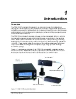
The transducer-optical element assembly (called the “optical assembly”) is the heart
of a PEM 100 photoelastic modulator. It consists of a rectangular or octagonal
“window” of optical material bonded to a quartz piezoelectric transducer. Both
optical element and transducer are tuned to the same frequency. When connected
to a driver circuit, this assembly oscillates and produces the time-varying
birefringence which is the basis of operation of the PEM.
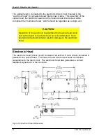
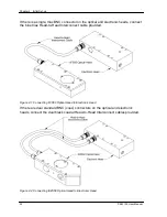
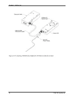
This assembly, consisting of the optical head, the electronic head, and the cable
which connects them, is a single circuit. It is not intended to operate unless all three
elements are together.
CAUTION
Operation of the electronic head without the optical head
attached may result in damage to the electronic head and
possibly to the controller.
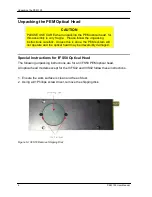
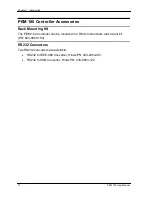
Optical Head
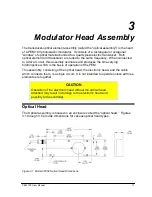
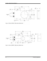
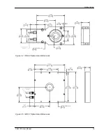
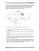
The Optical assembly is housed in an enclosure called the “optical head.” Figures
3.1 through 3.5 provide dimensions for various optical head types.
Figure 3.1 Model I/FS50 Optical Head Dimensions
Содержание PEM-100
Страница 1: ...PEM 100 PHOTOELASTIC MODULATOR USER MANUAL Hinds Instruments Inc P N 010 0000 021 UM Rev H ...
Страница 4: ......
Страница 8: ...Table Of Contents viii PEM 100 User Manual ...
Страница 12: ...Table of Tables xii PEM 100 User Manual ...
Страница 22: ...Unpacking the PEM 100 10 PEM 100 User Manual ...
Страница 46: ...Chapter 5 PEM 100 Controller Display 34 PEM 100 User Manual ...
Страница 52: ...Chapter 6 Operating the PEM 100 Controller 40 PEM 100 User Manual ...
Страница 68: ...Chapter 9 Troubleshooting 56 PEM 100 User Manual ...
Страница 74: ...Chapter 10 Maintenance 62 PEM 100 User Manual ...
Страница 88: ...Appendix A Calibration 76 PEM 100 User Manual ...
Страница 92: ...Appendix C Optical HeadSpecifications 80 PEM 100 User Manual ...
Страница 100: ......


