


CONFIGURATION
14
4 Configuration
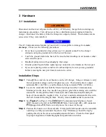
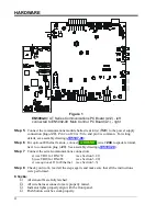
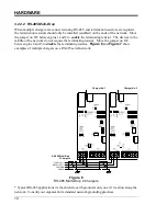
All user configurable items are controlled by two (2) groups of switches, and a setup program
to modify additional configuration parameters. The AT Series Communications Module
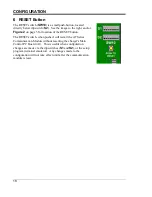
must be reset, after changes have been made, for them to take effect. To reset
communications, either
press
the RESET button (
SW10
) on the A12 pc board, or turn
off
then turn
on
, both the ac input (
CB1
) and dc output (
CB2
) circuit breakers.
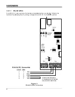
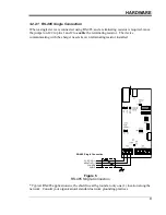
S1 is used to configure the communications interface. S2 is used to set the device address for
Modbus. Setting S1-1 to enable the Setup Program, allows modification to additional
configuration parameters.
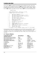
4.1 DIP Switch Settings
S1 Configuration
Position
Description
“ON” position
“OFF” position
DIP S1-1
Setup Program
Enabled
Disabled
DIP S1-2
Configuration
Parameters
*
User Values
Factory Default
Values
DIP S1-3
Protocol
DNP
Modbus
DIP S1-4
Modbus Protocol
ASCII
RTU
DIP S1-5
Serial Port
RS-485
RS-232
DIP S1-6
RS-232 Handshaking
Enabled
Disabled
DIP S1-7
Baud Rate
19200 bps
9600 bps
DIP S1-8
Ethernet Enable
Enabled
Disabled
*
- -
NOTICE
- -
See Configuration Parameters Below
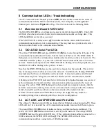
S2 Modbus Network Address Selection
Switch Position
Address bit
DIP S2-1
Net addr b7
DIP S2-2
Net addr b6
DIP S2-3
Net addr b5
DIP S2-4
Net addr b4
DIP S2-5
Net addr b3
DIP S2-6
Net addr b2
DIP S2-7
Net addr b1
DIP S2-8
Net addr b0
Modbus Slave Address Table
DIP S2
Slave
Address
1 2 3 4 5 6 7 8
1 0 0 0 0 0 0 0 1
2 0 0 0 0 0 0 1 0
3 0 0 0 0 0 0 1 1
4 0 0 0 0 0 1 0 0
5 0 0 0 0 0 1 0 1
6 0 0 0 0 0 1 1 0
…
…
…
…
…
…
…
…
…
255 1 1 1 1 1 1 1 1