background image


2


List of Figures


Hillstone   


Hillstone SG-6000 X-Series Hardware Reference Guide


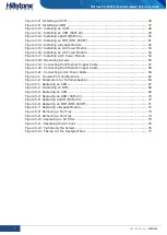
Figure 3-8: Installing an SCM ................................................................................ 46


Figure 3-9: Installing an IOM ................................................................................. 47


Figure 3-10: Installing an SCM .............................................................................. 48


Figure 3-11: Installing an SSM (SSM-20) ................................................................ 49


Figure 3-12: Installing a QSM (QSM-20) ................................................................. 50


Figure 3-13: Installing an IOM (IOM-16SFP) ............................................................ 51


Figure 3-14: Installing a Bypass Module ................................................................. 52


Figure 3-15: Installing an AC Power Module ............................................................ 53


Figure 3-16: Installing an AC Power Module ............................................................ 54


Figure 3-17: Installing a DC Power Module .............................................................. 54


Figure 3-18: Grounding Screws ............................................................................. 55


Figure 3-19: Connecting the Ethernet Copper Cable ................................................. 57


Figure 3-20: Connecting the Ethernet Copper Cable ................................................. 58


Figure 3-21: Connecting an AC Power Cable ............................................................ 58


Figure 4-1: Console Port Configuration ................................................................... 62


Figure 4-2: Parameters for Terminal Session ........................................................... 63


Figure 5-1: Replacing an SCM ................................................................................ 67


Figure 5-2:  Replacing an IOM ............................................................................... 68


Figure 5-3: Replacing an SCM ................................................................................ 69


Figure 5-4: Replacing an SSM (SSM-20) ................................................................. 70


Figure 5-5: Replacing a QSM (QSM-20) .................................................................. 70


Figure 5-6: Replacing an IOM (IOM-16SFP) ............................................................. 71


Figure 5-7: Replacing a Bypass Module ................................................................... 72


Figure 5-8: Removing a Fan Tray ........................................................................... 73


Figure 5-9: Removing a Fan Tray ........................................................................... 74


Figure 5-10: Replacing an Air Filter ........................................................................ 75


Figure 5-11: Replacing the Air Inlet ........................................................................ 76


Figure 5-12: Tightening the Screws ........................................................................ 76


Figure 5-13: Taking out the Dustproof Net .............................................................. 77


Содержание SG-6000-X10800

Страница 1: ...Hillstone StoneOS User Manual Hillstone SG 6000 X Series Hardware Reference Guide www hillstonenet com TW HW XS EN V2 0 Y18M06 ...

Страница 2: ...xic or hazardous substance in the material is below the limit requirement defined in Requirements for Concentration Limits for Certain Hazardous Substances in Electronic Information Products SJ T11363 2006 issued by Ministry of Information Industry of PRC Χ Indicates that this toxic or hazardous substance in the material exceeds the limit requirement specified in Requirements for Concentration Lim...

Страница 3: ...tallation Preparation Chapter 3 Installation Chapter 4 Boot and Configuration Chapter 5 Hardware Maintenance and Replacement Chapter 6 Troubleshooting Document Conventions This manual uses the following conventions for your convenience to read and understand Warning Indicates improper operation that may cause serious damage to equipment or injury to operators Thus operators must strictly follow th...

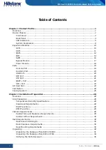
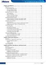
Страница 4: ...t 21 QSFP Port 22 SFP Port 23 SD Card Slot 24 CLR Button 25 Cooling System 25 Chapter 2 Installation Preparation 28 Overview 28 Site Preparation 28 Temperature Humidity Specifications 28 Cleanness Requirements 28 ESD Prevention 29 EMI Prevention 29 Cabinet Requirements 29 Cabinet Size and Clearance Requirements 29 Cabinet Airflow Requirements 30 Rack Requirements 30 Rack Size and Strength 30 Rack ...

Страница 5: ...unding the Chassis 55 Connecting the Console Cable 56 Connecting the Ethernet Optical Cable 56 Connecting an AC Power Cable 58 Connecting a DC Power Cable 59 Powering On Off the Device 60 Powering On Off SG 6000 X10800 60 Powering On Off SG 6000 X7180 60 Verification after Installation 61 Chapter 4 Boot and Configuration 62 Overview 62 Establishing a Configuration Environment 62 Console CON Connec...

Страница 6: ...lacing a Dustproof Net 75 Chapter 6 Troubleshooting 78 Overview 78 Losing the Administrator Password 78 Troubleshooting the Expansion Module 78 Troubleshooting the Cooling System 78 Troubleshooting the Power System 78 Troubleshooting the Configuration System 79 Copyright Information 80 ...

Страница 7: ... 17 Figure 1 24 SG 6000 X10800 AC Power Module 18 Figure 1 25 SG 6000 X10800 DC Power Module 19 Figure 1 26 SG 6000 X7180 AC Power Module 19 Figure 1 27 SG 6000 X7180 DC Power Module 19 Figure 1 28 Fan tray of SG 6000 X10800 26 Figure 1 29 Air Flow through the Chassis 26 Figure 1 30 Fan Tray 27 Figure 1 31 Air Flow through the Chassis 27 Figure 2 1 Position of Tongues to be Removed 31 Figure 2 2 S...

Страница 8: ...igure 3 19 Connecting the Ethernet Copper Cable 57 Figure 3 20 Connecting the Ethernet Copper Cable 58 Figure 3 21 Connecting an AC Power Cable 58 Figure 4 1 Console Port Configuration 62 Figure 4 2 Parameters for Terminal Session 63 Figure 5 1 Replacing an SCM 67 Figure 5 2 Replacing an IOM 68 Figure 5 3 Replacing an SCM 69 Figure 5 4 Replacing an SSM SSM 20 70 Figure 5 5 Replacing a QSM QSM 20 7...

Страница 9: ... 6 IOM Description 14 Table 1 7 Console Port Attributes 20 Table 1 8 Auxiliary Port Attributes 20 Table 1 9 USB Port Attributes 20 Table 1 10 SFP Port Attributes 21 Table 1 11 SFP Optical Module Attributes 21 Table 1 12 XFP Port Attributes 22 Table 1 13 XFP Optical Module Attributes 22 Table 1 14 QSFP Port Attributes 22 Table 1 15 QSFP Optical Module Attributes 23 Table 1 16 SFP Port Attributes 23...

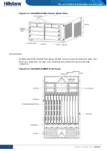
Страница 10: ...and lower TCO Hillstone SG 6000 X series product models include SG 6000 X7180 and SG 6000 X10800 For information about modular design see Hillstone SG 6000 X Series Expansion Modules Reference Guide Device Chassis Hillstone SG 6000 X10800 chassis is a standard 19 inch chassis that can be installed in one standard cabinet rack if the cabinet rack can handle the total weight of all hardware componen...

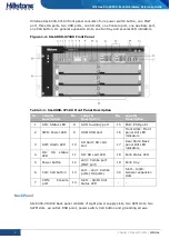
Страница 11: ...ference Guide Figure 1 2 SG 6000 X7180 Chassis Back View Front Panel Hillstone SG 6000 X10800 front panel consists of twelve general expansion slots two fan trays cable rack air inlet rack mounting ears ESD point and several LED indicators Figure 1 3 SG 6000 X10800 Front Panel ...

Страница 12: ...on No Label Description 1 STA Status LED 8 AUX Auxiliary port 15 ESD ESD point 2 PWR Power LED 9 USB USB port 16 Front Slots Front panel slot LED indicators 3 ALM Alarm LED 10 SD Card SD card slot 17 Rear Slots Back panel slot LED indicators 4 HA HA status LED 11 SD SD card LED 18 Fan0 status LED 5 Power button 12 e0 0 Combo port MGT port 19 Fan0 tray 6 CLR CLR button 13 e0 1 e0 3 Combo ports HA p...

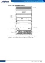
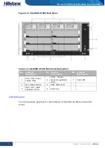
Страница 13: ...lstone Hillstone SG 6000 X Series Hardware Reference Guide Figure 1 5 SG 6000 X10800 Back Panel SG 6000 X7180 back panel consists of four power supply slots four general expansion slots two SCM slots one fan tray and grounding screws ...

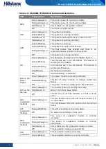
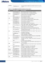
Страница 14: ...7180 Back Panel Description No Label Description No Label Description No Label Description 1 PS0 PS3 Power supply slots 4 Slot7 Slot10 General expansion slots 7 Fan1 LED 2 Grounding screws 5 ESD ESD point 3 SC0 SC1 SCM expansion slots 6 Fan1 tray LED Indicators The following table describes the LED indicators of SG 6000 X10800 and SG 6000 X7180 ...

Страница 15: ...ces are in an HA cluster This device is working as the salve Red Blinking HA function has failed Off High Availability is disabled LED on the power supply Green Always on The power module is working normally Orange Blinking The fan of power module or voltage output has failed Off The power module is using power off protection LED on the fan tray Green Always on The cooling system is working normal...

Страница 16: ...e Green Blinking Two devices are in an HA cluster This device is working as the master Orange Blinking Two devices are in an HA cluster This device is working as the salve Red Blinking HA function has failed Off High Availability is disabled SD Green Always on SD card has been inserted and is in normal status Green Blinking SD card is transmitting data Red Always on SD card has been inserted but c...

Страница 17: ...odule is working normally Green Blinking The power module is standby Red Always on The fan of power module or voltage output has failed Red Blinking The power module is using overcurrent protection Off No power input LED on the fan tray Green Always on The cooling system is working normally Red Always on One or more fans have failed Off The fan tray is not fully inserted or it has a circuit error ...

Страница 18: ...ize W D H SG 6000 X10800 442 0mm x 715 0mm doesn t include the depth of lever x 797 0mm SG 6000 X7180 440 0mm x 590 0mm x 225 0mm Weight SG 6000 X10800 Net weight 85 78kg the fan trays are included Gross weight 165 0kg total weight with product and its packaging SG 6000 X7180 Net weight 34 2kg product alone Gross weight 54 0kg total weight with product and its packaging Power Rating SG 6000 X10800...

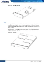
Страница 19: ...WM three power modules and two fan trays The SSM module QSM module and IOM module are divided into half width and full width Only SSM 200 QSM 200 IOM 2Q8SFP 200 IOM 2Q8SFP and IOM 8SFP are full width modules the others are half width modules The installation method of full width modules and half width modules are different see Installing Expansion Modules SCM System Control Module SCM is a hardwar...

Страница 20: ... is a hardware platform card which performs data processing other than QoS You must install at least one SSM in the device and can install more to escalate system performance SSMs should be installed in the general expansion slots SG 6000 X10800 uses the SSM model of SSM 300 SG 6000 X7180 uses the SSM model of SSM 200 and SSM 100 Figure 1 9 SSM 300 ...

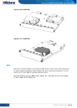
Страница 21: ...1 SSM 100 QSM QoS Service Module QSM is a hardware platform card which solely performs Quality of Service QoS processing Without QSM the device cannot process QoS You can install one or more QSMs in general expansion slots SG 6000 X10800 uses the QSM model of QSM 300 SG 6000 X7180 uses the QSM model of QSM 200 and QSM 100 ...

Страница 22: ...13 Chapter 1 Product Profile Hillstone Hillstone SG 6000 X Series Hardware Reference Guide Figure 1 12 QSM 300 Figure 1 13 QSM 200 Figure 1 14 QSM 100 ...

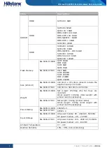
Страница 23: ...d can install more to increase port amount IOM should be installed in general expansion slots but the IOM 2Q8SFP and IOM 8SFP module cannot be installed in the Slot7 expansion slot Table 1 6 IOM Description Model Type Product IOM P40 300 12 SFP ports 2 QSFP ports SG 6000 X10800 IOM 16SFP 100 16 SPF ports SG 6000 X7180 IOM 4XFP 100 4 XFP ports SG 6000 X7180 IOM 2Q8SFP 200 2 QSFP ports SG 6000 X7180...

Страница 24: ...15 Chapter 1 Product Profile Hillstone Hillstone SG 6000 X Series Hardware Reference Guide Figure 1 16 IOM 16SFP 100 Figure 1 17 IOM 4XFP 100 Figure 1 18 IOM 2Q8SFP 200 ...

Страница 25: ...ont panel to forward the data Only SG 6000 X10800 supports SWM You should install at least one SWM in the device You can install a second SWM for redundancy SWM can only be installed in the SWM slots of the back panel If the device has two SWMs installed they work in the redundancy mode in which the backup module takes the master module s work when the master fails SG 6000 X10800 uses the SWM mode...

Страница 26: ...power failure or system reboot the two networks are connected directly by the bypass module therefore the device is bypassed You can install bypass module s in general expansion slots For more information about Bypass configuration please refer to StoneOS User Manual Hillstone bypass module has the following two types Single mode bypass module IOM 2SM BE Multi mode bypass module IOM 2MM BM SG 6000...

Страница 27: ... or DC power modules You can install a third and fourth power module in the device to offer redundancy When four power modules are installed in the device you are suggested to connect two of the power modules to a power source and connect the other two to a different power source This can ensure that when a power source fails the other power modules powered by the different source can begin to wor...

Страница 28: ...er Module Figure 1 26 SG 6000 X7180 DC Power Module Ports The ports available for Hillstone SG 6000 X series are Console port Auxiliary port USB port SFP port XFP port QSFP port and SFP port This section explains the attributes of each port Console Port Hillstone SG 6000 X series provides a RS 232C asynchronous serial console port for you to configure the appliance ...

Страница 29: ...Cable Auxiliary Port Hillstone SG 6000 X series provides an RS 232C asynchronous serial auxiliary port Table 1 8 Auxiliary Port Attributes Attribute Description Connector RJ 45 Port Standard RS 232C Baud Rate 9600 19200 38400 57600 115200 bit s Services Aux port is used for debugging Transmission Medium Console Cable USB Port Hillstone SG 6000 X series provides two USB Host ports Table 1 9 USB Por...

Страница 30: ...commended If SFP optical module is applied to SFP port you should use cable with LC type optical connector Hillstone SG 6000 X series supports the following types of SFP optical modules All modules are hot swappable Table 1 11 SFP Optical Module Attributes Attribute Description Short haul Multimode Optical Module 850nm Medium haul single mode Optical Module 1310nm Long haul Single mode Optical Mod...

Страница 31: ...nm Ultra long Haul Single mode Optical Module 1550nm Connector LC Fiber Type 50 125μm multimode fiber 62 5 125μm multi mode fiber 9 125μm single mode fiber 9 125μm single mode fiber 9 125μm single mode fiber Maximum Transmission Distance 0 3km 984 3ft 0 033km 108 3ft 10km 40km 80km Central Wavelength 850nm 850nm 1310nm 1550nm 1550nm Caution To avoid dust falling into the XFP socket you should plac...

Страница 32: ...smission Distance 0 1km 0 3km 10km Central Wavelength 850nm 850nm 1310nm Caution To avoid dust falling into the QSFP socket you should place a rubber dust cap originally in the accessory box over the QSFP port SFP Port IOM 2Q8SFP 200 IOM 2Q8SFP and IOM 8SFP provide eight SFP ports IOM P40 300 provides twelve SFP ports Table 1 16 SFP Port Attributes Attribute Description Connector SFP Frame Format ...

Страница 33: ...FP port SD Card Slot Hillstone SG 6000 X7180 has an SD card slot for SD storage card on the front panel SD card stores the data of the Network Behavior Control log messages The highest capacity for SD card on the device is 32GB To install an SD card take the following steps 1 Ensure that the write protection switch is off so that it can be written 2 Face the front panel of the appliance 3 Insert t...

Страница 34: ...00 X10800 take the following steps 1 Press the CLR button in the pinhole of a SCM module and press the CLR button in the pinhole of another SCM module in five minutes 2 When the STA and ALM LEDs turn to constantly red the appliance begins to restore to the original factory settings 3 The system reboots after the default settings restored To restore the factory default settings of SG 6000 X7180 tak...

Страница 35: ...sis cage The air is exhausted out the air outlet which is at the top of the rear panel and the side of the chassis Figure 1 28 Air Flow through the Chassis Each fan tray of SG 6000 X7180 has six fans and an air filter The fan trays are vertically located in the Fan0 slot of the front panel and Fan1 slot of the back panel Both the fan tray and air filter can be replaced see Replacing a Fan Tray and...

Страница 36: ...erence Guide Figure 1 29 Fan Tray From the front of the chassis there is air intake on the left side of the device Air is pushed from the left intake and then goes through the chassis cage The air is exhausted out the right of the chassis Figure 1 30 Air Flow through the Chassis ...

Страница 37: ...in indoor place You should follow the instructions in this section to ensure that your site is properly prepared for the device installation Temperature Humidity Specifications Table 2 1 specifies the environmental temperature and relative humidity required for the device Table 2 1 Temperature Humidity Specifications Description Value Temperature Normal operation ensured in temperature range of 0 ...

Страница 38: ...oupling inductance coupling electromagnetic radiation and common impedance including the grounding system coupling To prevent or reduce EMI Take measures to protect the power system from the interference of the power grid Separate the protection ground of the device from the grounding device or lighting protection grounding device of the power supply equipment as far as possible Keep the device fa...

Страница 39: ...trong enough to support the weight of a fully configured device which is approximately 194 0kg Rack Clearance Requirements When planning the installation site make sure the surroundings of the rack have sufficient clearance for ventilation and maintenance operation For better heat dissipation the air flow around the chassis should not be blocked Allow certain clearance between the chassis and othe...

Страница 40: ...nside the shipping wooden case Do not unpack it until you are ready to begin installation To unpack the package take the following steps 1 Move the shipping wooden case to a place as close to the installation site as possible where you have enough room to remove packages you are suggested to use a forklift or cart 2 Position the wooden case with the arrows pointing up 3 There re many tongues in th...

Страница 41: ...nce Guide Figure 2 2 Straightening the Tongue 5 After all the tongues around the bottom are straightened two people are required to lift up the wooden case and remove it Figure 2 3 Removing the Wooden Case 6 Take out the accessory box and EPE Check the products received with the packing list ...

Страница 42: ...base a Use the cross screwdriver to remove the total ten screws on the vertical fixed baffles as shown by number 1 on both sides b Use the spanner to remove the total eight screws on the horizontal fixed baffles as shown by number 2 on both sides c Remove the baffles from the device and then four people are required to take the device from the base by handles on both sides ...

Страница 43: ...er modules and an accessory box The carton is 655 0mm wide 880 0mm deep and 605 0 high The total weight of packaging materials and the hardware is 53 0kg Note The device is maximally protected inside the shipping carton Do not unpack it until you are ready to begin installation To unpack the package take the following steps 1 Move the shipping carton to a place as close to the installation site as...

Страница 44: ...e 2 6 Packages and Hardware Components Warning Do not discard the packing materials which can be used for repacking or transportation Verifying the Parts Received When you receive the product a packing list is included inside the accessory box Verify the parts and items you received against the packing list If any part is missing contact a service representative Hillstone provides different expans...

Страница 45: ...n Off the Device 8 Verify the installation according to Verification after Installation Safety Requirements To avoid personnel injury or harm to the device follow the guidelines in this section Note that this manual does not cover all the safety requirements warnings or guideline for operating electric devices General Safety Warnings The following guidelines apply to any operational situations Mak...

Страница 46: ...pets Some components can be impaired by static voltages To minimize the potential of electrostatic discharges ESD follow the rules Always use ESD wrist strap which should be directly contact with your skin Caution For safety periodically check the resistance value of the ESD strap The measurement should be in the range of 1 to 10 Mega ohms When you handle the chassis make sure one end of your ESD ...

Страница 47: ...38 Chapter 3 Installation Hillstone Hillstone SG 6000 X Series Hardware Reference Guide Figure 3 1 ESD Point of SG 6000 X10800 on the Front Panel Figure 3 2 ESD Point of SG 6000 X7180 on the Front Panel ...

Страница 48: ...39 Chapter 3 Installation Hillstone Hillstone SG 6000 X Series Hardware Reference Guide Figure 3 3 ESD Point of SG 6000 X10800 on the Back Panel ...

Страница 49: ...afety regulations and have fire extinguishers in the room The equipment room forbids smoking and open fires In the event of fire the safety of personnel is the primary concern Cut off all the power supplies and then use fire extinguishers Installing the Device in a Rack This section describes how to install a device in a rack A fully configured SG 6000 X10800 weighs approximately 194 0kg and a ful...

Страница 50: ...d it requires at least four people to install the appliance To install SG 6000 X10800 manually take the following steps 1 Wear an ESD strap and connect the other end of the strap to the ESD point on the chassis See ESD Prevention 2 Make sure the device is not powered and it will not be powered during the removing process 3 Dismantle all the removable components including power modules all expansio...

Страница 51: ...Before powering on the device all empty slots should be covered with blank plates To prevent the equipment damage or personal injury four people are needed to install the device You should use the Handles on the chassis side to remove the device to the rack or cabinet To avoid damaging the chassis you shouldn t use the lever of modules to remove the device Installing SG 6000 X7180 Installing the D...

Страница 52: ...nting ear to mark the positions of floating nuts on the front rack posts 3 Attach rack mounting ears to the left and right side panels of the chassis respectively Figure 3 6 Installing Rack mounting Ears 4 Load the chassis steadily on the center of the lift platform 5 Use the lift to move the chassis to the rack or the cabinet tray and then move away the lift 6 Install a mounting screw into each o...

Страница 53: ...appliance To install the device without a lift take the following steps 1 Wear an ESD strap and connect the other end of the strap to the ESD point on the chassis See ESD Prevention 2 Make sure the device is not powered and it will not be powered during the removing process 3 Dismantle all the removable components including power modules all expansion modules SSM SCM QSM and IOM blank plates and f...

Страница 54: ...n SSM QSM IOM Bypass Tools Required The following tools are required to install an expansion module Cross screwdriver ESD wrist strap Installing an SCM SWM SG 6000 X10800 supports up to two SCMs and two SWMs SCM is located in the slot SCM0 and SCM1 of the back panel and SWM is located in the slot SWM0 and SWM1 of the back panel The following takes SCM as an example to introduce how to install an S...

Страница 55: ...sistant 7 Tighten the screws on the SCM with a cross screwdriver 8 To install more SCMs repeat Step 3 to 7 Installing an SSM IOM QSM Bypass The SSM IOM QSM or Bypass module of SG 6000 X10800 can be installed in any slot of slot1 to slot12 You can choose the slot according to needs The following takes IOM as an example to introduce how to install an SSM IOM QSM or Bypass module To install an IOM ta...

Страница 56: ... Rotate the levers to outside and slide the expansion module straight into the slot along the guide rail Figure 3 9 Installing an IOM 6 When the lever head is inserted into the expansion slot you should rotate the levers to the front of the module and slide the IOM into the slot until you feel resistant 7 Tighten the screws on the IOM with a cross screwdriver 8 To install more IOMs repeat Step 3 t...

Страница 57: ... back panel To install an SCM take the following steps 1 Wear an electrostatic discharge ESD strap around your bare wrist and connect the strap to an ESD point on the chassis See ESD Prevention 2 Take SCM out from its antistatic bag 3 Identify the slot of SCM 4 If the slot is covered with a blank plate loose its screws with a cross screwdriver and remove the plate 5 Position the SCM so that its fr...

Страница 58: ...river and remove the plate 5 Position the SSM so that its front side faces you and slide the SSM into the slot until you feel resistant as shown below Figure 3 11 Installing an SSM SSM 20 6 Tighten the screws on the SSM with a cross screwdriver 7 To install more SSMs repeat Step 2 to 6 Note The tray is installed in each expansion slot at the factory and you can install the half width modules by ta...

Страница 59: ...s repeat Step 2 to 6 Note The tray is installed in each expansion slot at the factory and you can install the half width modules by taking the above steps When installing the full width modules such as SSM 200 QSM 200 IOM 2Q8SFP 200 IOM 2Q8SFP and IOM 8SFP you should remove the tray and install the modules by taking the above steps Installing an IOM IOM has four types and should be installed in Sl...

Страница 60: ...OM 2Q8SFP 200 IOM 2Q8SFP and IOM 8SFP you should remove the tray and install the modules by taking the above steps Installing a Bypass Module Hillstone SG 6000 X7180 supports two types of bypass module single mode bypass module IOM 2SM BE and multi mode bypass module IOM 2MM BE The bypass module is installed in Slot1 to Slot10 To install a bypass module take the following steps 1 Wear an electrost...

Страница 61: ... ESD wrist strap Installing an AC DC Power Module of SG 6000 X10800 SG 6000 X10800 requires at least three AC power modules or four DC 48V power modules If each slot of device is installed with expansion module please install at least three AC or four DC 48V power modules The following takes AC power module as an example to introduce how to install an AC or DC power module To install an AC power m...

Страница 62: ...is slot You can hear a click of the lock stuck in the chassis Verify that the panel of the power module is plain with the chassis panel Figure 3 15 Installing an AC Power Module Installing an Power Module of SG 6000 X7180 Installing an AC Power Module To install an AC power module take the following steps 5 Make sure the power module is not connected to any power source and there is no chance it w...

Страница 63: ...To install a DC power module take the following steps 1 Make sure the power module is not connected to any power source and there is no chance it will be powered during the process 2 Wear an electrostatic discharge ESD strap around your bare wrist and connect the strap to an ESD point on the chassis See ESD Prevention 3 Face the back panel of the chassis 4 Slide the power module straight into the ...

Страница 64: ...ire The grounding screws are in the back panel of the chassis as shown below Note that Hillstone does not provide grounding wire Figure 3 18 Grounding Screws To ground the chassis take the following steps 1 Wear an electrostatic discharge ESD strap around your bare wrist and connect the strap to an ESD point on the chassis See ESD Prevention 2 Ensure all cable ends are clean and bright 3 Connect t...

Страница 65: ...e Console port of the appliance and then connect the DB 9 connector of the cable to the console terminal The Auxiliary AUX port is used to configure the slave SCM Connecting the AUX port is similar to connecting the Console port Connecting the Ethernet Optical Cable IOM supports SFP ports and XFP ports SFP port can accommodate SFP optical module or copper SFP transceiver when you use optical SFP m...

Страница 66: ...tion the optical module should be inserted into SFP port before installing the LC type connector to the optical module the copper SFP module should be connected by crossover cable or straight through cable For XFP ports insert the XFP optical module into the XFP port before connecting the LC type connector to the module Keep the followings in mind when connecting fiber cables The curvature radius ...

Страница 67: ...r Cable The AC power cable is shipped with the chassis To connect the AC power cable take the following steps 1 Take the AC power cable out of the accessory box 2 Insert the coupler end of the cable into the inlet of the power module as shown below Figure 3 21 Connecting an AC Power Cable 3 Snap the wire bail on the power supply over the power cord to prevent the power cord from accidentally disen...

Страница 68: ... has been properly installed according to the Installing a DC Power Module 4 Check the DC power cable and the plug and make sure they are not loosened If they are loosened you should use the screwdriver to tighten the screw 5 Use a DC cable to connect the RTN terminal of the appliance to the terminal of the power source use another DC cable to connect the 48Vdc terminal to the terminal of the powe...

Страница 69: ...age the device will be automatically started If the power cables are connected with the device respectively or the device is shut down manually you should press the red button on the front panel To power off the device press the red button on the front panel for four seconds to shut down the device immediately Note The device requires at least two fan trays and one SCM to work normally A power swi...

Страница 70: ...ke sure all the cables are properly connected Verify that the chassis is grounded The air inlet and outlet are not blocked and the surroundings have sufficient space for hot air dissipation Ensure all hardware components including expansion modules power modules and fan trays are located in the proper slots Verify the voltage of power source complies with the required voltage ...

Страница 71: ...SSH Console CON Connection For initial system configuration you have to establish a Console connection environment connect the device to a console terminal through its Console port To connect the PC to the CON port of the device take the following steps 1 Set up a local configuration environment Connect the Console port to the serial port of the PC through a console cable as shown below Figure 4 1...

Страница 72: ...ommands to configure or view running status Enter a question mark to get help on commands whenever you want WebUI The ethernet0 0 e0 0 port or MGT port has a default IP address of 192 168 1 1 24 and all the management functions of this port are enabled by default Administrators can access the WebUI through e0 0 To log in the appliance s WebUI take the following steps 1 Set up the IP address of the...

Страница 73: ...device you should be familiar with device features and your network deployment Different device position in the network requires different topology design working mode and policy configuration The basic configurations may include 1 Create security zones including the link layer L2 and network layer L3 Bind different interfaces to correct security zones respectively 2 Assign IP addresses to interfa...

Страница 74: ...Components When you maintain the hardware components note that Always wear ESD strap on around your bare wrist See ESD Prevention When you inspect or move the modules hold the module with both hands without touching the electric components on the module The removed module should be placed into an antistatic bag or on an antistatic table with component side up Tools Required Cross screwdriver ESD w...

Страница 75: ... plate over the slot to avoid dust falling into the chassis Replacing a DC Power Module To replace a DC power module take the following steps 1 Switch off the power source and remove the DC power cable from the power source 2 Wear an electrostatic discharge ESD strap around your bare wrist and connect the strap to an ESD point on the chassis See ESD Prevention 3 Loose the screws of the DC power ca...

Страница 76: ...p to an ESD point on the chassis See ESD Prevention 2 Use a cross screwdriver to loosen SCM screws until they pop out 3 Rotate the lever to outside till the lever head is out of the expansion slot 4 Hold the module with one hand and pull it straight out of the expansion slot along the guide rail Figure 5 1 Replacing an SCM 5 Put the removed module into an antistatic bag or on a flat antistatic tab...

Страница 77: ...p to an ESD point on the chassis See ESD Prevention 2 Use a cross screwdriver to loosen IOM screws until they pop out 3 Rotate the lever to outside till the lever head is out of the expansion slot 4 Hold the module with one hand and pull it straight out of the expansion slot along the guide rail Figure 5 2 Replacing an IOM 5 Put the removed module into an antistatic bag or on a flat antistatic tab...

Страница 78: ...igure 5 3 Replacing an SCM 4 Put the removed module into an antistatic bag or on a flat antistatic table 5 Install a replacement module see Installing an SCM Note If you do not want to install a new module apply a blank plate over the slot to avoid dust falling into the chassis Replacing an SSM The following section takes SSM 20 as an example to describe how to replace an SSM To replace an SSM tak...

Страница 79: ...id dust falling into the chassis Replacing a QSM The following section takes QSM 20 as an example to describe how to replace a QSM To replace a QSM take the following steps 1 Wear an electrostatic discharge ESD strap around your bare wrist and connect the strap to an ESD point on the chassis See ESD Prevention 2 Use a cross screwdriver to loosen SCM screws until they pop out 3 Hold the screws and ...

Страница 80: ...ss screwdriver to loosen IOM screws until they pop out 4 Hold the screws and pull the IOM straight out of the chassis as shown below Figure 5 6 Replacing an IOM IOM 16SFP 5 Put the removed module into an antistatic bag or on a flat antistatic table 6 Install a replacement module see Installing an IOM Note If you do not want to install a new module apply a blank plate over the slot to avoid dust fa...

Страница 81: ...e to fan failure or air filter block you need to change the fan tray or the air filer The fan tray is hot swappable Note You should change your fan trays at least once a year even they can work normally Replacing a Fan Tray When the fan tray cannot work normally or has been used for a year you should change the fan tray You can buy the fan tray alone from Hillstone To prevent over heating you shou...

Страница 82: ...ng you should install the replacement fan tray within one minute after the existing fan tray is removed If system detects over heating it will automatically switch off the power supply You are suggested to buy a backup fan tray firstly before maintaining the cooling system Replacing a Fan Tray of SG 6000 X7180 To replace a fan tray take the following steps 1 Wear an electrostatic discharge ESD str...

Страница 83: ...ing it will automatically switch off the power supply Replacing an Air Filter The air filter is inside the fan tray of SG 6000 X7180 To avoid system overheating install the fan tray with a replacement air filter immediately after it is removed To replace the air filter take the following steps 1 Remove the fan tray according the Step 1 to 4 in Replacing a Fan Tray 2 Place the fan tray on the opera...

Страница 84: ...ray within one minute after the existing fan tray is removed If the system detects over heating it will automatically switch off the power supply Replacing a Dustproof Net The dustproof net should be installed in the air inlet of SG 6000 X10800 You are suggested to install the dustproof net for the device to prevent intrusion of dust If the dustproof net is used for a long time the dust will be ac...

Страница 85: ... Hardware Reference Guide Figure 5 11 Replacing the Air Inlet 3 Position the air inlet on the workbench so that the dustproof side faces you Use a cross screwdriver to loosen four screws until they pop out Figure 5 12 Tightening the Screws 4 Take out the dustproof net from the air inlet ...

Страница 86: ... edge of the slot Slide the air inlet straight into the slot till it is fully seated in the chassis slot You can hear a click of the lock stuck in the chassis 6 Use a cross screwdriver to tighten four screws of the dustproof net Note The dustproof net can be bought alone from Hillstone You are suggested to back up a dustproof When the dustproof which is in use need to be replaced you can replace i...

Страница 87: ...view the status of all modules on the command line interface Troubleshooting the Cooling System The cooling system consists of two fan trays and an air filter A malfunctioning fan tray or dust full air filter can influence the ventilation through the chassis When the system is over heated it will shut itself down When the cooling system is malfunctioned take the following steps to troubleshoot Use...

Страница 88: ...ion System The Console configuration terminal shows system booting message when the appliance is powered on If the configuration system has failed it displays error information or nothing at all If the configuration terminal shows no information perform the following steps Make sure the power supply is correctly connected and powered on Verify the Console cable is connected properly Ensure the ter...

Страница 89: ...Hillstone PnPVPN UTM Plus are trademarks of Hillstone Networks All other trademarks or registered marks are the property of their respective owners Hillstone Networks assumes no responsibility for any inaccuracies in this document Hillstone Networks reserves the right to change modify transfer or otherwise revise this publication without notice Hillstone Networks Website www hillstonenet com posts...

Отзывы: