background image


DS-TD10M-1   

Multi-Target  Speed-Measuring  Radar   


User Debugging Manual 


Содержание DS-TD10M-1

Страница 1: ...DS TD10M 1 Multi Target Speed Measuring Radar User Debugging Manual...

Страница 2: ...E LAW THIS MANUAL AND THE PRODUCT DESCRIBED WITH ITS HARDWARE SOFTWARE AND FIRMWARE ARE PROVIDED AS IS AND WITH ALL FAULTS AND ERRORS HIKVISION MAKES NO WARRANTIES EXPRESS OR IMPLIED INCLUDING WITHOUT...

Страница 3: ...ENT OF ANY CONFLICTS BETWEEN THIS MANUAL AND THE APPLICABLE LAW THE LATER PREVAILS Symbol Conventions The symbols that may be found in this document are defined as follows Symbol Description Provides...

Страница 4: ...r 1 Radar Installation 4 1 1 Installation Parameters 4 1 2 Install Radar 4 1 3 Wire Radar 5 Chapter 2 Operation via Radar Debugging Software 7 2 1 Overview 7 2 2 Running Environment 7 2 3 Install Soft...

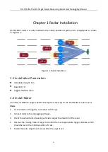
Страница 5: ...rigger distance 28 m 1 2 Install Radar The radar installation angle is determined by the scale 10 on the DS TD10M 1 radar mount Steps 1 Fix the radar on the gantry or crossbar with hoop 2 Connect rada...

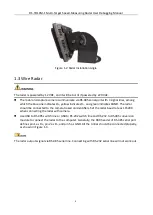
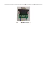
Страница 6: ...dicates DGND The radar should be connected to the camera based on identifiers Set the radar baud rate as 115200 when connecting the radar with camera Use USB to RS 485 switch line or USB to RS 232 swi...

Страница 7: ...DS TD10M 1 Multi Target Speed Measuring Radar User Debugging Manual 6 Figure 1 3 RS 485 DB9 Header Connection...

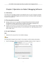
Страница 8: ...ET FrameWork4 0 or above version the kit is included in the installation package to the computer It is recommended to use 64 bit version of windows 7 Hardware environment It is required that the compu...

Страница 9: ...Path 4 Click Next to continue The setup wizard will complete the software installation automatically as shown in Figure 2 3 Figure 2 3 Install Software 5 Click OK and a shortcut named MultiLaneVelocit...

Страница 10: ...ice Connection Click Connect and select a communication mode to enable the communication between software and radar Device Disconnection Click Disconnect to disable the communication between software...

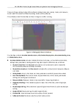
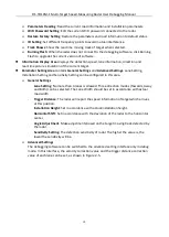
Страница 11: ...gs Lane Setting Installation Setting and Sensitivity Setting can be configured in this area General Settings Lane Setting No more than 4 lanes is allowed Three direction modes Towards Away and Both ca...

Страница 12: ...Radar Steps 1 Select Device Connect and the connection setting dialog box will pop up As shown in Figure 2 6 there are two connection methods WIFI connection and Serial connection The initial default...

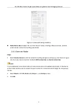
Страница 13: ...rameters trigger distance and installation height are set view the real time vehicle status displaying window to check whether the vehicle is in the corresponding lane or not Set the angle correction...

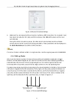
Страница 14: ...etectable For instance if the trigger distance of Towards Direction is set as 28 meters the appearance distance should be set as about 35 meters Secondly it is necessary to ensure that the detected la...

Страница 15: ...nnects to pin 2 and the green one connects to pin 5 Detecting targets failed Check radar parameters and adjust the pitch angle to enable the radar beam to cover the trigger position For instance if th...

Страница 16: ...DS TD10M 1 Multi Target Speed Measuring Radar User Debugging Manual 15...

Отзывы: