CameraLink Line Scan Camera
·
User Manual
27
Phase A
Phase B
Line Inp ut 1
Line Input 2
Line input 1 is
selected as the
input signal for
phase A
Line input 2 is
selected as th e
input signal for
phase B
Phase A Input
Phase B Input
Shaft Encod er
Software
Module
Line Trigger
Module
Output
The final output
of module is line
trigger s ignal
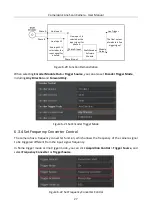
Figure 6-20
Function Demonstration
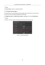
When selecting Encoder Module Out as Trigger Source, you can also set Encoder Trigger Mode,
including Any Direction and Forward Only.
Figure 6-21
Set Encoder Trigger Mode
6.3.4 Set Frequency Converter Control
The camera has a frequency converter function, which allows the frequency of the camera signal
to be triggered different from the input signal frequency.
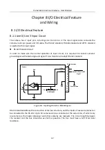
In frame trigger mode or line trigger mode, you can click Acquisition Control > Trigger Source, and
select Frequency Converter as Trigger Source.
Figure 6-22
Set Frequency Converter Control
Содержание CameraLink
Страница 1: ...CameraLink Line Scan Camera User Manual ...
Страница 72: ...CameraLink Line Scan Camera User Manual 62 Figure 10 10 Update Firmware via USB Data Cable ...
Страница 84: ...CameraLink Line Scan Camera User Manual 74 ...
Страница 85: ...UD17814B ...


