

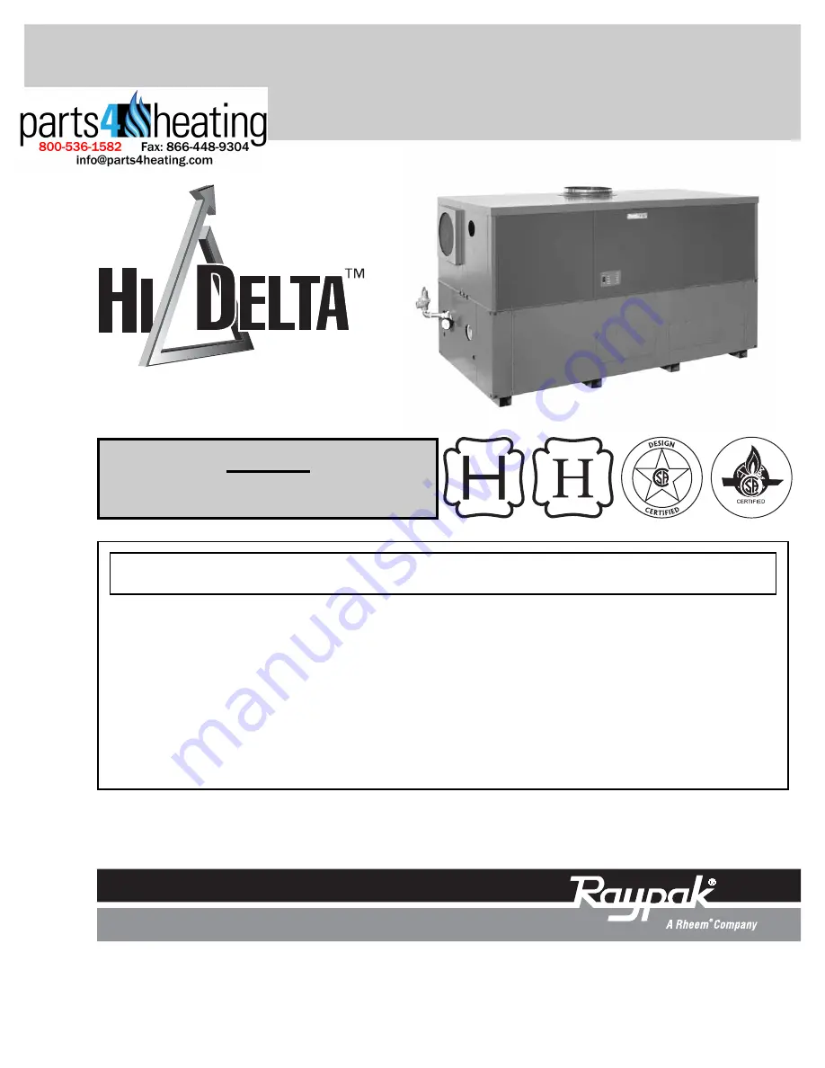
INSTALLATION AND OPERATING
INSTRUCTIONS
CATALOG NO. 1000.511A
Effective: 09-08-06
Replaces: 03-15-05
P/N 241259 Rev. 1
WARNING:
If these instructions are not followed exactly, a fire or explosion may result causing property dam-
age, personal injury or death.
FOR YOUR SAFETY:
Do not store or use gasoline or other flammable vapors and liquids or other com-
bustable materials in the vicinity of this or any other appliance. To do so may result in an explosion or fire.
WHAT TO DO IF YOU SMELL GAS:
• Do not try to light any appliance.
• Do not touch any electrical switch; do not use any phone in your building.
• Immediately call your gas supplier from a neighbor's phone. Follow the gas supplier's instructions.
• If you cannot reach your gas supplier, call the fire department.
Installation and service must be performed by a qualified installer, service agency or the
gas supplier.
This manual should be maintained in legible condition and kept adjacent to the heater or in another safe place for
future reference.
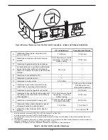
Models
992A-2342A Types H, WH & P
L
W


