


# of NVMe
drives
supported
Processor
quantity
Cable part number From
To
Power cable
part number
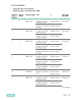
2
3
869957-001
1
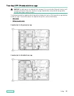
Drive box 4, 2SFF Premium
drive cage
Butterfly 6 slot riser
870479-001
3
2
4
869957-001
1
Drive box 2, 8SFF (6+2)
Premium drive cage
Butterfly 6 slot riser
870479-001
3
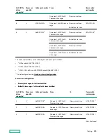
2
4
869957-001
1
Drive box 4, 2SFF Premium
drive cage
Butterfly 6 slot riser
870479-001
3
4
4
869957-001
1
Drive box 2, 8SFF (6+2)
Premium drive cage
Butterfly 6 slot riser
870479-001
3
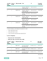
Drive box 4, 2SFF Premium
drive cage
Butterfly 6 slot riser
4
4
869957-001
1
Drive box 1, 8SFF (6+2)
Premium drive cage
Drive box 2, 8SFF (6+2)
Premium drive cage
Butterfly 6 slot riser
870479-001
3
Butterfly 6 slot riser
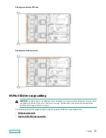
* To order spare cables, use the following kits and spare part numbers.
•
1
NVMe cable kit (877983-001)
•
2
NVMe cable kit (881703-001)
•
3
USB 3.0 Ext. 600mm+SASPWR BP cable kit (881699-001)
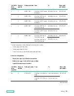
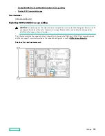
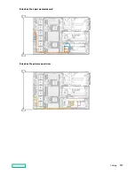
Server riser configuration:
•
Primary riser cage—4 port slimline riser installed
•
Butterfly riser cage—6 slot and 2 slot risers installed
•
4 port NVMe mezzanine card installed
# of NVMe
drives
supported
Processor
quantity
Cable part number From
To
Power cable
part number
16
3
870508-001
2
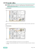
Drive box 2, 8-NVMe drive
cage
4 port mezzanine card 870479-001
3
Drive box 3, 8-NVMe drive
cage
Primary 4 port riser
Table Continued
Cabling
154
Содержание HPE ProLiant DL580 Gen10
Страница 11: ...Eight bay SFF NVMe drive cage Six bay SFF HDD Two bay NVMe SSD Premium drive cage Component identification 11...
Страница 12: ...Two bay SFF Premium drive cage Front panel LEDs and buttons Power switch module Component identification 12...
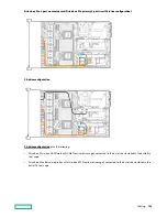
Страница 106: ...Four processor configuration Hardware options installation 106...
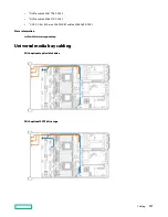
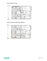
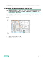
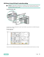
Страница 161: ...Drive box 1 to butterfly riser cage Drive box 2 to primary riser cage 4 drive configuration Cabling 161...
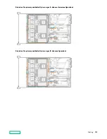
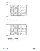
Страница 163: ...Drive box 2 to 4 port mezzanine card Drive box 3 to primary 4 port riser Cabling 163...


