2
HermanMiller
Installation Instructions
1BN0MC rev A
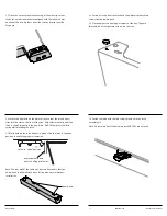
1.3 Place the second tray bracket on top of the wire clip so that
the holes on the tray bracket are aligned with the inboard holes
on each of the wire brackets and slide the tray bracket over the
Hinge pin.
1.4 Fasten wire clip and tray bracket to the worksurface with two
screws from hardware pack.
1.5 Place bumpers on front upper corners of the tray. They are
located with a cross-pattern etched into the tray.
1.6 Locate the tray latch on the work surface so that the latch hooks/
clips into the slot on the front of the tray. Adjust this manually until the
latch is seated properly in the tray. Note: Do NOT compress the latch
spring while locating the latch.
1.7 While holding the latch bracket in place, slide the latch to the open
position to verify the proper orientation.
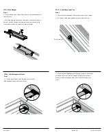
Note: The rear wall of the cable tray has two knock-outs that can
be removed to allow easier access for the monitor arm bracket
installation.
Verify clearance here
prior to drilling pilot holes
Latch in “open” position
Knock-outs
1.8 Fasten the latch with the two screws provided in the latch
assembly kit.
Note: V-Grommets from the hardware pack 1BCD8C are not used.


