background image

17730-241


61 

Component Replacement

AR2

 40K • 46K

ASSEMBLY

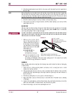
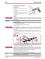
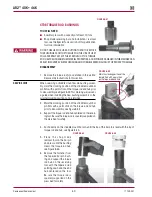
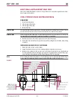
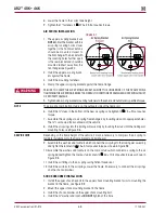
1 .  Clean and inspect the inner diameter of the torque rod end hubs, see Figure 8-45 .

SERVICE HINT 

dO NOT

 use a paraffinic oil, or soap base lubricant . Such lubricants can cause adverse reactions 

with the bushing, causing premature failure . 

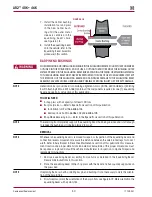
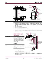
2 .  Lubricate the inner diameter of the torque rod end hubs and the new bushings with NLGI#2 – 

EP (Extreme Pressure) lithium base grease, see Figure 8-46 .

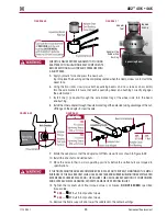
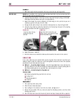
3 .  Support the torque rod end hub centered on the receiving tool . Be sure the torque rod is 

squarely supported on the press bed for safety . 

4 .  Re-align the bar pin bushings to the mark made before removal as shown in Figure 8-42 .
5 .  Using the shop made tool, place the installer tool on the bushing and press in . The bushing 

must be centered within the hub of the torque rod .

FIguRE 8‑45 

FIguRE 8‑46

6 .  Wipe off the excess lubricant . 
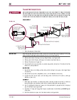
7 .  Install the torque rod as detailed in the Torque Rod Assembly instructions in this section . 

CROSS TuBE

A cross tube seldom requires replacement, usually only when it has been bent, possibly due to 

hitting an object . A bent cross tube may cause misalignment of the axles, and must be replaced 

immediately to eliminate abnormal tire wear . 


Method 1 — Equalizing Beam Removal

 - Follow the Equalizing Beam component replace-

ment procedure in this section . Within the procedure, after removal of the equalizing beams 

when the equalizing beams are separated, remove and replace cross tube .


Method 2 — Center Bushing End plug Removal


YOu wILL NEEd


Center Bushing End Plug (see Parts Lists section)


Cutting Torch


Welding Equipment


Hole Saw

dISASSEMBLY 

1 .  Use a work bay with a level surface .
2 .  Chock the front steer axle wheels .
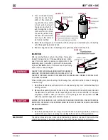
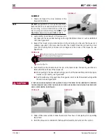
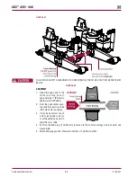
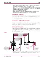
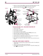
3 .  Use a cutting torch to make two cuts in the cross tube, see Figure 8-47 .
4 .  Remove the cut section of the cross tube and slide the remaining sections out of the center 

bushings and discard .

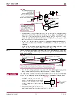
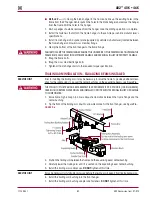
5 .  Use a 2½" hole saw and remove only one (1) center bushing end plug from the suspension .

Apply NLGI #2-EP (Extreme Pressure)

lubricant to the inner diameter of torque 

rod end hub and bushings


Inspect and clean the inner 

diameter of torque rod 

end hubs 

Содержание AR2 series

Страница 1: ...Longitudinal and Transverse Torque Rods 22 Saddle Connection 23 Cross Tube 24 Shock Absorber 25 Air Fittings 26 Axle Stops 26 Section 7 Alignment Adjustments Ride Height 27 Axle Pinion Angle 29 Drive Axle Alignment 30 Lateral Alignment 31 Bar Pin with shims Alignment 32 Section 8 Component Replacement Fasteners 35 Frame Hanger 35 Trailing Arm 36 Trailing Arm Bushing 38 Air Spring 40 Shock Absorber...

Страница 2: ...ice repair or rebuild of this product The information in this publication contains parts lists safety information product specifications features proper maintenance ser vice repair and rebuild instructions for the AR2 suspension Hendrickson reserves the right to make changes and improvements to its products and publications at any time Contact Hendrickson Tech Services for information on the lates...

Страница 3: ...ing saddle assembly of existing RT RTE suspensions The heavy duty trailing arm saddle assembly provides lighter weight good articulation and optimal ground clearance Large volume air springs Rolling lobe design provides variable spring rates to deliver superior ride quality Equalizing beam AR2 is compatible with 40K 46K capacity Hendrickson RT RTE walking beams If required rigid forged beams or ro...

Страница 4: ... be replaced with rubber center bushings Bronze center bushings are not compatible with transverse torque rods NOTE Any comparison to other suspensions should consider all of these components including axle brackets 2 Contact Hendrickson for applications that may exceed GVW approval ratings 3 Site Travel Rating Ratings are limited to no more than 5 of vehicle operation at speed not to exceed 5 mph...

Страница 5: ...njury to service personnel or possibility of improper service methods which may damage the vehicle or render it unsafe This is the safety alert symbol It is used to alert you to potential personal injury hazards Obey all safety messages that follow this symbol to avoid possible injury or death Additional Notes or Service Hints are utilized to emphasize areas of procedural importance and provide su...

Страница 6: ...rements section of this publication Failure to so can cause Adverse Vehicle Handling resulting in personal injury or property damage If beam end bushing movement or looseness is noted inthe equalizing beam end hub do not operate the vehicle Replace the end bushings and all connecting parts The above condition can result in costly repair downtime possible separation of components Adverse Vehicle Ha...

Страница 7: ...ailure to do so can cause damage to the air spring AND OR mounting brackets and void warranty Air spring LOWER MOUNTING STUDS IFTHE AIR SPRING IS BEING REMOVED for an alternate repair IT IS MANDATORYTO LUBRICATETHE LOWER AIR SPRING FASTENERS WITH PENETRATING OIL AND REMOVE WITH HANDTOOLSTO PREVENT DAMAGE TO THE LOWER AIR SPRING MOUNTING STUD Failure TO DO SO Can CAUSE COMPONENT DAMAGE AND VOID WAR...

Страница 8: ... VEHICLE HANDLING POSSIBLE PERSONAL INJURY OR PROPERTY DAMAGE AND WILL VOID ANY APPLICABLE WARRANTIES USE ONLY HENDRICKSON AUTHORIZED REPLACEMENT PARTS PROCEDURES ANDTOOLS A TECHNICIAN USING A SERVICE PROCEDURE OR TOOL WHICH HAS NOT BEEN RECOMMENDED BY HENDRICKSON MUST FIRST SATISFY HIMSELF THAT NEITHER HIS SAFETY NOR THE VEHICLE S SAFETY WILL BE JEOPARDIZED BYTHE METHOD ORTOOL SELECTED INDIVIDUAL...

Страница 9: ...MPROPER ACTIONS CAN DAMAGE THE EQUALIZING BEAM ASSEMBLY AND CAN CAUSE Adverse Vehicle Handling AND POSSIBLE PERSONAL INJURY OR PROPERTY DAMAGE Parts Cleaning Solvent cleaners can be flammable poisonous and cause burns To help avoid serious personal injury carefully follow the manufacturer s product instructions and guidelines and the following procedures 1 Wear proper eye protection 2 Wear clothin...

Страница 10: ...ply this tool Hendrickson Part No 66086 105 OTC Part No 302030 Visit otctools com Adapter style end Bushing center bushing Trailing arm bushing tools 28K 52K lb Rubber Bushings Hendrickson Part No 66086 102 OTC Part No 1764 Visit otctools com Center Bushing tools 40K lb Rubber Bushings Hendrickson Part No 66086 100 OTC Part No 1746 Visit otctools com Part OTC P N 1 Remover 310248 2 Installer 31024...

Страница 11: ... Plus Hendrickson Part No 66086 000L Torque rod Bushing tools These shop made tools are designed for the torque rod bushings Bushing tools are to be made from cold rolled steel or equivalent Drawing is for reference only Hendrickson does not supply these tools Ultra rod Bushing Ultra rod plus and XTRB Bushing XTRB Bushing ...

Страница 12: ...Parts Lists 12 17730 241 AR2 40K 46K SECTION 5 Parts Lists ...

Страница 13: ...y Nos 19 23 2 19 45289 003 Adapter Tube 2 20 45871 000 Trailing Arm Adapter 4 21 30550 005 1 14 UNS x 9 Bolt 2 22 22962 008 1 Hardened Washer 4 23 08017 000 1 14 UNS Locknut 2 24 58795 000 Saddle Cap 4 25 06696 000 7 8 14 UNF Saddle Cap Stud 8 26 22962 002 7 8 Hardened Washer 8 27 04842 000 7 8 14 UNF Locknut 8 28 Air Spring Assembly 65455 002L Forward 2 65652 002L Rear 2 29 Air Spring Bracket 654...

Страница 14: ...essure Protection Valve See plumbing diagram1 71 66029 000 In Cab Air Dump Switch See plumbing diagram 1 72 48940 000 In Cab Air Switch Plate Not Shown 1 NOTE Item included in assembly kit only part not sold separately Hendrickson s part number is stamped on the torque rod for identification Be sure to include the suffix number when ordering this number indicates torque rod length Hendrickson s tw...

Страница 15: ...sive or adverse contact with other components Damaged or cracked parts Within the first 100 Miles Within the first 1 000 Miles or 100 Hours Every 6 Months 1 200 hours 25 000 Miles whichever comes first Inspection of fasteners for proper torque as recommended in the Torque Specification section of this publication with special attention to the following suspension connections Frame hanger to traili...

Страница 16: ...suspension for wear and damage Look for bent or cracked parts Replace all worn or damaged parts Frame hanger bracket Check for any signs of loosening or damage at the pivot connec tions Check for cracks damage or any signs of looseness at the mounting fasteners Replace all worn or damaged parts Height control valve and air lines Check the suspension air system for air leaks Check all air lines for...

Страница 17: ...d or replaced 3 Consult the vehicle manufacturer for inspection component repair and replacement instructions Figure 6 1 Figure 6 2 Adapter Style 1 Inspect the 2 64 mm diameter holes in each of the axle bracket legs as shown in Figure 6 3 Figure 6 3 2 Remove any burrs or material left there by the old adapters 3 Use a new adapter as a gauge for fit being sure it enters the holes from the outside o...

Страница 18: ...ct suspension components for signs of movement or excessive wear Inspect alignment shims in equalizing beam end for looseness Lightly tap on the align ment shims to see if they can be moved If movement is detected tighten fasteners to the proper torque value see Figure 6 6 Inspect equalizing beam end connection for signs of excessive wear or looseness SERVICE HINT An equalizing beam end connection...

Страница 19: ... may indi cate a loose connection 2 If bar pin end bushing movement or looseness is detected in the equalizing beam end hub replace the end bushings and all connecting parts Refer to the Component Replacement section of this publication 3 Check and record torque values for each 1 bar pin fastener see Figure 6 6 Ensure all fasten ers are tightened to the following At the locknuts tighten to 525 75 ...

Страница 20: ...asten ers will be necessary to correct position refer to the Adapter Style End bushings in the Component Replacement section Physical INSPECTION Adapter Style If bushing movement or looseness is noted in the equalizing beam end hub do not operate the vehicle Replace the rubber end bushings and all connecting parts The above condition can result in costly repair downtime possible separation of comp...

Страница 21: ...eplacement is when one or more of the following conditions apply Visual inspection of contact areas on the shim reveals signs of excessive wear The thickness of any single leg on the shim is less than the measurement shown in Figure 6 10 replacement of bar pin shim is required Figure 6 10 Original Thickness of Shim Leg Minimum Thickness Required Part Number 1 8 3 2 mm 0 123 3 1 mm 50131 000 3 16 4...

Страница 22: ...N RESULT IN ADVERSE VEHICLE HANDLING Adverse Vehicle Handling POSSIBLE TIRE CONTACT WITH THE FRAME PREMATURE COMPONENT DAMAGE OR SEVERE PERSONAL INJURY All torque rods need to be inspected for looseness by one of the following methods Method 1 ForTractor applications only with brakes applied slowly rock the empty vehicle with power while a mechanic visually checks the action at both ends Method 2 ...

Страница 23: ...centered on each equalizing beam center bushing The center bushing inner metal is full seated to the saddle The saddle cap fasteners are tightened to the proper torque see Figure 6 13 Saddle cap fasteners have a phosphate oil coating THETRAILING ARM Assemblies are ATTACHEDTOTHE CENTER BUSHINGS OF EACH EQUALIZING BEAM WITHTWO 2 SADDLE CAPS EACH SADDLE CAP USESTWO 2 studsTO CLAMPTHE CENTER BUSHING I...

Страница 24: ...NOT USE THE SUSPENSION CROSS TUBE bar pin axle brackets AS A JACKING POINT SEE FIGURE 6 15 Refer to vehicle manufacturer for proper jacking instructions ACCEPTABLE LIFTING POINTS FOR A VEHICLE AT THE RATED LOAD INCLUDE BUT NOT LIMITED TO THE AXLE equalizing beam AND THE VEHICLE FRAME RAIL REFER TO THE VEHICLE MANUFACTURER FOR PROPER JACKING INSTRUCTIONS The AR2 cross tube connects the two 2 equali...

Страница 25: ...ood condition and the end is cut square Check to see if the tubing is binding bent or being pulled upon 4 Visually inspect the air fitting s O ring seal for signs of damage or contamination Axle Stops The axle stops are supplied by the vehicle manufacturer Check the axle stop to frame fasteners for proper torque Follow the vehicle manufacturer s specifications Visually inspect for damage or excess...

Страница 26: ...The AR2 suspension is equipped with a premium seal on the shock however this seal will allow for misting to appear on the shock body misting is not a leak and is considered acceptable Misting is the process whereby very small amounts of shock fluid evaporate at a high operating temperature through the upper seal of the shock When the mist reaches the cooler outside air it condenses and forms a fil...

Страница 27: ...f the vehicle 4 When checking or adjusting ride height verify and maintain the vehicle s air system at full operating pressure Figure 7 1 SERVICE HINT It is very important that the height control valves be cycled com pletely before and after any ride height adjustments The cycling of the height control valve will help to make the adjustment more accurate PRIOR TO AND DURING DEFLATION A N D I N F L...

Страница 28: ... the bottom of the frame rail to the axle centerline see Figure 7 2 10 Measure the referenced ride height Dimension B from the top of the of the trailing arm saddle to the centerline of the center bushing see Figure 7 2 Note A vehicle equipped with dual height control valves must measure the ride height at each height control valve location Table 7 1 11 Compare the actual Dimension A ride height t...

Страница 29: ...that the air springs are above the proper ride height 8 Lower the height control valve arms to exhaust the suspension air system until the suspension is at proper ride height NOTE Adjustments to one 1 height control valve may affect ride height setting on the other height control valve Verify ride height is correct at both height control valves whenever an adjustment is made Figure 7 3 9 Use a 1 8...

Страница 30: ...t adjustable Computerized alignment equipment is the preferred method of measuring alignment To calculate the shim thickness required the target offset must be converted to thrust angle see alignment equipment manufacturer for procedures If however computerized axle alignment equipment is not available refer to the following Inspection in this section Proper alignment is essential for maximum ride...

Страница 31: ...cturer s specifications prior to the alignment of the remaining drive axle 11 Using a trammel bar measure the distance from the spindle center of the front drive axle to the spindle center of the rear drive axle on both sides of the vehicle see Figure 7 5 C and D 12 Calculate the difference between measurements C and D a If the measurements are within the vehicle manufacturer s specifications then...

Страница 32: ...ally designed tight tolerance steel shims which fill the 3 8 9 5 mm total gap between the bushing s bar pin and the axle bracket legs The gap must be filled by placing the shims on the bushing assembly in one of the positions shown in Figure 7 7 or 7 9 Hendrickson has three 3 shim design options for alignment see Figure 7 10 NOTE Drive axle alignment with suspensions equipped with adapter style be...

Страница 33: ...he rear of the bar pin LocationY EACH bar pin end bushing has one 1 inboard and one 1 outboard alignment shim for a total of FOUR 4 sets ofTWO 2 alignment shims per suspension Each set of alignment shims on a bar pin end bushing for a particular beam end bushing must be installed in the same orientation Shim orientation may differ for each beam bushing See Figure 7 7 FAILURE TO FOLLOW THESE WARNIN...

Страница 34: ...e fasteners from the end bushing where the bar pin alignment shim adjustment is being made 6 Adjust shim thickness to move the axle in the desired direction see Figure 7 9 7 Install new end bushing fasteners and tighten to At the locknut to 525 75 foot pounds torque At the bolt head to 575 75 foot pounds torque 8 Remove support and lower the vehicle 9 Verify the axle s alignments are within the ve...

Страница 35: ...ront wheels 2 Support the frame of the vehicle at ride height PRIORTO AND DURING DEFLATION AND INFLATION OFTHE AIR SUSPENSION SYSTEM ENSURETHAT ALL PERSONNEL AND EQUIPMENT ARE CLEAR FROM UNDERTHE VEHICLE AND AROUNDTHE SERVICE AREA FAILURETO DO SO CAN CAUSE SERIOUS PERSONAL INJURY DEATH OR PROPERTY DAMAGE 3 See Air Spring Cautions and Warnings in the Important Safety Notice section of this publica ...

Страница 36: ... 8 Install the trailing arm bushing fasteners and adapter assembly 9 Tighten trailing arm bushing locknut to 470 25 foot pounds torque 10 See additional Air Spring Cautions and Warnings in the Important Safety Notice section of this publication prior to deflating or inflating the air system 11 Connect the height control valve linkage rod s to the height control valve arm s to inflate the suspensio...

Страница 37: ... beam center bushing see Figure 8 2 4 Install the trailing arm saddle caps see Figure 8 2 DO NOT tighten at this time SERVICE HINT If needed tip the front of the trailing arm down to allow clearance for the front hanger It may be necessary to install a block of wood behind the trailing arm to keep it from tipping backwards see Figure 8 2 Figure 8 2 5 Install the trailing arm into the front hanger ...

Страница 38: ...Adjustments section of this publication 19 Remove the wheel chocks Trailing Arm Bushing You will need A shop press with a capacity of at least 100 tons Adapter set tool Hendrickson Part No 66086 102 Refer to Special Tools section of this publication for the tools to remove and install the trailing arm bushings Receiving tool The receiving tool is a shop made tool which completely supports the beam...

Страница 39: ...OT re bush or otherwise use trailing arm that has been damaged Failureto replacetrailing armthat has been damaged from bushing removal can result in the failure of that trailing arm leading to Adverse Vehicle Handling and possible personal injury or property damage When installing rubber trailing arm bushings the following steps will minimize the chance of damaging a new bushing 1 Clean the bushin...

Страница 40: ...rings on the same trailing arm if one 1 air spring requires replacement NOTE The following component replacement procedure is for one 1 air spring replacement Duplicate procedure if more that one air spring requires replacement DISASSEMBLY 1 Chock the front wheels 2 Support the frame of the vehicle at ride height IMPORTANT NOTE If the air springs are deflated it will be necessary to raise the fram...

Страница 41: ...t the air spring to the trailing arm assembly and tighten the locknuts to 25 5 foot pounds torque as shown in Figure 8 6 5 Assemble the washers and locknuts on the combo stud which connect air spring to the frame hanger bracket Tighten the combo stud locknut to 60 10 foot pounds torque as shown in Figure 8 6 6 Install the air fitting to the air spring using Teflon thread seal 7 Install the air lin...

Страница 42: ...o 60 10 foot pounds torque see Figure 8 7 Height Control Valve DISASSEMBLY 1 Chock the wheels of vehicle 2 Disconnect the leveling valve arm s from the rubber grommet s PRIORTO AND DURING DEFLATION AND INFLATION OFTHE AIR SUSPENSION SYSTEM ENSURETHAT ALL PERSONNEL AND EQUIPMENT ARE CLEAR FROM UNDERTHE VEHICLE AND AROUNDTHE SERVICE AREA FAILURETO DO SO CAN CAUSE SERIOUS PERSONAL INJURY DEATH OR PRO...

Страница 43: ...in the Alignment Adjustments section of this publication 8 Remove the wheel chocks Equalizing Beam SERVICE HINT It is recommended to remove both equalizing beams and the cross tube as a group even if only one 1 equalizing beam needs service DISASSEMBLY 1 Chock the wheels of the steer axle 2 Raise and support the drive axles with safety stands 3 Remove the tires 4 Support the pinion angle of the dr...

Страница 44: ...riorto removing both equalizing beams support the pinion of each drive axle Failure to do so can result in personal injury or allow the axles to shift making reassembly more difficult 10 Slowly lower the floor jacks and remove the equalizing beams from the axle brackets 11 Slide the equalizing beams off the cross tube and out from under the vehicle 12 Remove the floor jacks from under the equalizi...

Страница 45: ... This is a normal function of the bar pin bushings SERVICE HINT Installing the front bar pin bushings if equipped prior to the rear bar pin bushings will ease in the installation of the equalizing beam THE WEIGHT OF THE equalizing beam ASSEMBLY IS APPROXIMATELY 155 POUNDS 70 kg CARE SHOULD BE TAKEN AT REMOVAL AND INSTALLATION TO PREVENT PERSONAL INJURY OR DAMAGE TO COMPONENTS 4 If the suspension i...

Страница 46: ...orary bolt from the inboard bar pin hole and complete installation of the inboard alignment shim DISCARD USED FASTENERS ALWAYS USE new FASTENERSTO COMPLETE A REPAIR FAILURETO DO SO COULD RESULT IN FAILURE OF THE PART OR MATING PARTS Adverse Vehicle Handling PERSONAL INJURY OR PROPERTY DAMAGE 10 Install the new 1 inboard bar pin fasteners DO NOT tighten at this time 11 Repeat Steps 8 through 10 for...

Страница 47: ...n the same orientation as prior to disassembly DISCARD USED FASTENERS ALWAYS USE new FASTENERSTO COMPLETE A REPAIR FAILURETO DO SO COULD RESULT IN FAILURE OF THE PART OR MATING PARTS Adverse Vehicle Handling PERSONAL INJURY OR PROPERTY DAMAGE 25 Tighten the bar pin end fasteners to At the locknuts tighten to 525 75 foot pounds torque At the bolt head tighten to 575 75 foot pounds torque Figure 8 1...

Страница 48: ...s a shop made tool which completely supports the beam hub being serviced and is tall enough to receive the bushing as it is being pressed in or out refer to the Special Tools section of this publication DISCARD USED FASTENERS ALWAYS USE NEW FASTENERSTO COMPLETE A REPAIR FAILURETO DO SO COULD RESULT IN FAILURE OF THE PART OR MATING PARTS Adverse Vehicle Handling PERSONAL INJURY OR PROPERTY DAMAGE D...

Страница 49: ...personal injury or property damage Figure 8 17 1 Measure the inside diam eter of the equalizing beam s center bushing bore and the cen ter bushing s outside diameter The specification of the equalizing beam s center bore on a new AR2 equalizing beam Inside Diameter 4 740 0 004 120 39mm 0 10 mm Each measurement is to be taken as the average of any two readings at 90 degrees in the same plane see Fi...

Страница 50: ...tyle tool Refer to Special Tools section of this publication Installation tool Part No 66086 103 Removal tools Part No 66086 104 and 66086 105 Shop Made Receiving tool Refer to the Special Tools section of this publication Note The receiving tool completely supports the equalizing beam hub being serviced and is tall enough to receive the bushing as it is being pressed in or out Removal NOTE Whenev...

Страница 51: ...ure ofthat beam leadingto Adverse Vehicle Handling and possible personal injury or property damage When installing bar pin end bushings the following steps will minimize the chance of damaging a new bushing 1 Clean the end hub bores with emery cloth or hone removing any nicks or metal buildup from bushing removal 2 Measure the equalizing beam end hub bore inner diameter and the bushing outer diame...

Страница 52: ...e bolt holes in the end bushing are in line with the beam axis see Figure 8 23 NOTE The end bushing must be square with the equalizing beam end hub before pressing the end bush ing into the equalizing beam End bushings pressed in at an angle will damage the end bushing and the equalizing beam Figure 8 23 5 Verify the end bushing s outer metal is square with the end hub Damage to the equalizing bea...

Страница 53: ...ury or allow the axles to shift making reassembly more difficult 4 Support the pinion angle of the drive axles to prevent axle movement during service 5 Remove and discard the saddle cap fasteners from both inboard and outboard sides of the equalizing beam 6 Remove the saddle caps refer to Saddle Cap Assembly in this section Figure 26 7 Raise the vehicle s frame just enough to create a 13 mm gap b...

Страница 54: ...t adapter tool with the tapered end down on top of the rubber end bushing see Figure 8 29 Figure 8 29 Check to ensure proper alignment of tooling adapters with equalizing beam components before applying full hydraulic pressure with a shop press 18 Apply hydraulic force and remove the old bushing 19 Inspect the axle bracket legs per the Beam End Axle Brackets Physical Inspection for Adapter Style b...

Страница 55: ...he cut off flange on the adapter to clear the axle Figure 8 32 Figure 8 33 9 Rotate the adapters so that the adapter cut off flats are vertical as shown in Figure 8 32 10 Install the end shaft and slotted nuts 11 Place the axles in their normal operating positions before the slotted nuts are torqued to specifications If the tightening torques recommended below are not properly maintained the metal...

Страница 56: ...te the quantity and orientation of the lon gitudinal torque rod shims It is required that the longitudinal torque rod shims are installed in the same orientation and location as removed to preserve the existing alignment 3 Remove the torque rod mounting fasteners and shims if equipped 4 Remove the fasteners that connect the longitudinal torque rod to the cross member and axle brackets 5 Remove lon...

Страница 57: ...ers 4 Remove the transverse torque rod 5 If servicing the inner spacer plates or outer backup plates remove the 5 8 fasteners from the frame rails see Figure 8 35 INSPECTION 1 Inspect the torque rod mating surfaces and rubber bushings for any wear or damage Repair as necessary 2 Inspect the torque rod for straightness wear or cracks Replace as necessary 3 Inspect the inner spacer plate outer backu...

Страница 58: ...ol and installation removal tool refer to the Special Tools section of this publication for more information Funnel Tools refer to the Special Tools section of this publication for more information ULTRA ROD Tool Part No 66086 001L ULTRA ROD PLUS Tool Part No 66086 000L Disassembly 1 Remove torque rods as detailed in Torque Rod Disassembly instructions in this section DO NOT USE HEAT OR USE A CUTT...

Страница 59: ...ust have the mounting flats positioned at zero degrees to the shank of the torque rod see Figure 8 38 Figure 8 38 4 Push directly on the straddle mount bar pin or the tapered stud The bushing must be cen tered within the end hubs of the torque rod When pushing in the new rubber bushings overshoot the desired final position by approx imately 3 16 4 76 mm see Figure 8 39 Push the rubber bushing agai...

Страница 60: ... hub prior to disassembly see Figure 8 42 This marking will serve as a guide when installing the new bushing assembly so the original clocking position can be retained 2 Mark the clocking position of the straddle mount bar pin flats with a paint stick on the torque rod end hub prior to disassembly see Figure 8 42 3 Support the torque rod end hub centered on the receiv ing tool Be sure the torque r...

Страница 61: ...ection CrossTube A cross tube seldom requires replacement usually only when it has been bent possibly due to hitting an object A bent cross tube may cause misalignment of the axles and must be replaced immediately to eliminate abnormal tire wear Method 1 Equalizing Beam Removal Follow the Equalizing Beam component replace ment procedure in this section Within the procedure after removal of the equ...

Страница 62: ...hing bore to approximately 1 25 4 mm depth of weld and debris 2 From the open center bush ing slide the new cross tube into both center bushings 3 It may be necessary to use a floor jack under one 1 or both equalizing beams to align the cross tube 4 Position the end plug 6 35 mm recessed in the center bushings and tack weld see Figure 8 48 5 Check end plug position final weld shall be a 6 35 mm fi...

Страница 63: ...correct amount of articulation allowed for the rear suspension After AR2 installation is complete check for proper clearance with all suspension and chassis components FASTENERS Hendrickson recommends when servicing the vehicle replace all removed fasteners with new equivalent fasteners Maintain correct torque values as specified See Hendrickson s Torque Specifications section of this publication ...

Страница 64: ...he fifth wheel and re install after AR2 suspension installation is completed 5 Mark the centerline of the old suspension on both sides of the frame 6 Disconnect and remove the old suspension Leave the walking beams installed unless being re bushed Preparation and inspection of Suspension 1 Clean the frame rail from rust and debris 2 Inspect the frame rail for any cracks or damage Repair or replace...

Страница 65: ...to inhibit rust prior to installation of the AR2 suspension components Figure 9 4 Height Control Valve and Linkage SERVICE HINT Prior to drilling any holes in the frame or cross member gusset it is recommended that the height control valve and linkage be fitted for proper location within the confines of the chassis Assembly NOTE It may be necessary to modify the height control valve mounting brack...

Страница 66: ...r dump switch installation instructions Refer to the Parts List section of this publication SUSPENSION AIR SYSTEM PRESSURE GAUGES Hendrickson recommends when installing an AR2 suspension conversion kit to have two 2 in dash air pressure gauges installed These gauges will help determine equal loading of the vehicle as well as indicate any potential suspension air system problem If in dash air press...

Страница 67: ...ation Trailing Arm Installation Equalizing Beams Installed Service Hint Prior to installing the trailing arm it may be necessary to raise the frame to provide additional clear ance for the saddle studs to go over the center bushings on the equalizing beams see Figure 9 6 THE WEIGHT OF THE TRAILING ARM ASSEMBLY IS APPROXIMATELY 225 POUNDS 102 kilograms CARE SHOULD BETAKEN AT REMOVAL AND INSTALLATIO...

Страница 68: ...semble the air springs to air spring frame hangers by inserting studs into appropriate holes The combo stud faces outboard of the vehicle 8 Install the air springs into the trailing arm assembly by inserting the studs into the trailing arm mounting holes see Figure 9 8 SERVICE HINT Depending on the frame height of the vehicle it may be necessary to compress the air spring to facilitate installatio...

Страница 69: ...and fasteners DO NOT tighten at this time 6 Install the air springs into the upper air spring brackets 7 Install the shock absorber on the upper mounting bracket 8 Raise the trailing arm up indexing the air spring studs into the trailing arm see Figure 9 6 9 Install the lower shock mounting hardware into the trailing arm 10 Final torque on the trailing arm mounting collars will need to be done aft...

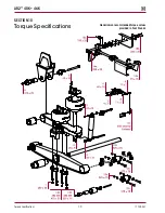
Страница 70: ...Torque Specifications 70 17730 241 Hendrickson recommended torque values provided in Foot Pounds AR2 40K 46K SECTION 10 Torque Specifications ...

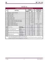
Страница 71: ...16 18 UNC 11 1 10 Height Control Valve Linkage Clamp 2 Until Securely Fastened 11 Height Control Valve Bracket to Frame 4 13 UNC 60 10 12a Bar Pin Bushing at the Locknut 8 1 8 UNC 525 75 12b at the Bolt Head 8 1 8 UNC 575 75 13a Bar Pin Bushing Adapter Style AR2 46K 4 1 16 UNF 470 25 13b AR2 40K 4 16 UNF 225 15 14A Transverse Torque Rod to Axle Bracket at the Locknut 2 1 12 UNF 200 25 14B at the B...

Страница 72: ...tments section Vehicle leans Air spring s not inflated to specification Check air supply to air spring and check ride height see Ride Height in the Alignment Adjustments section of this publication Load not centered Redistribute load Frame twisted Straighten the frame per vehicle manufacturer guidelines Axle housing bent or broken Replace axle housing per vehicle manufacturer guidelines and align ...

Отзывы: