background image

Introduction

HELLASSAT Point&Play Setup Manual - page 5

Version 1.2 - May 2008

Safety precautions

This section lists the safety precautions to follow when installing the antenna.

Safety precautions are grouped into warnings and cautions.

Local regulations

Always install the HELLAS SAT antenna in accordance with local regulations.

Warnings

warning

 refers to an action or situation that could result in 

injury, long term health hazard 

or death

 if you do not follow the instructions.

Antenna

- RF radiation hazard: The area between the antenna reflector and the iLNB feed horn exposes 

hazardous electromagnetic field levels during transmission. Do not place your head and/or body 

in that zone while the system is operational. Take the necessary precautions to prevent access 

to the antenna by children or unauthorised persons.

IPmodem

- There are no user-serviceable parts in the IPmodem. There are potentially lethal voltages inside 

the equipment. It should only be opened by a technician trained and certified to service the 

product.

- When the IPmodem is powered on, DC voltages are present on the rear panel Tx and Rx 

connectors.

- Do not expose the IPmodem to rain or moisture to prevent fire or shock hazard. Do not expose 

the IPmodem to dripping or splashing and do not place any objects filled with liquids, such as 

vases, on it.

- Postpone antenna and IPmodem installation until there is no risk of thunderstorm or lightning 

activity in the area.

- To prevent electrical shock, if the unit is provided with a polarized plug, do not connect the plug 

into an extension cord, receptacle or other outlet unless the plug can be fully inserted with no 

part of the blades exposed.

- Connect the in-line power supply input power cord to a properly grounded three-prong AC 

outlet. Do not use adapter plugs or remove the grounding prong from the plug.

- Do not use the in-line power supply power cord when damaged in any form.

Содержание Newtec Point&Play

Страница 1: ...Version 1 2 May 2008 Newtec Point Play Setup Manual...

Страница 2: ......

Страница 3: ...ty precautions 5 Material provided in the box 7 Material you need to provide yourself 9 Installation overview 10 2 Setting up the antenna 11 Step 1 Choosing a suitable location 12 Step 2 Mounting the...

Страница 4: ...HELLAS SAT Point Play Manual page 3 Version 1 2 May 2008...

Страница 5: ...e 9 Follow the entire procedure When installing the antenna it is important that you follow the entire procedure step by step When pointing the antenna you may need to repeat the steps from the sectio...

Страница 6: ...erviceable parts in the IPmodem There are potentially lethal voltages inside the equipment It should only be opened by a technician trained and certified to service the product When the IPmodem is pow...

Страница 7: ...ith static by first touching the coaxial cable connector when it is attached to the earth grounded coaxial cable outlet Always first touch the coaxial cable connector on the HELLAS SAT IPmodem when yo...

Страница 8: ...nual page 7 Version 1 2 May 2008 Material provided in the box 50 mm 8 mm 6 mm 20 mm 16 mm 1 1 x 3 2 x 2 2 x 4 1 x 5 1 x 12 1 x 13 1 x 15 4 x 14 1 x 18 1 x 19 1 x 20 1 x 22 1 x 23 1 x 21 1 x 11 4 x 16...

Страница 9: ...LNB clamp 1 5 iLNB Interactive Low Noise Block downconverter 1 6 Screw 50 mm M6 2 7 Screw 20 mm M6 1 8 Screw 16 mm M6 4 9 Hex key 1 10 Cap 1 11 F connectors 4 12 Parker Screw 1 13 Feed arm 1 14 Satell...

Страница 10: ...pecifications UL style 1007 1569 PVC insulated 300V 80 C C S A Type TR 64 18AWG Yellow Green attached to 4 3 mm insulation and 5 0 mm non insulation supported ring terminal Geographical pointing data...

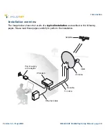
Страница 11: ...10 Installation overview The image below shows the results of a typical installation as described in the following pages Please read these pages carefully to perform the installation Rx cable iLNB An...

Страница 12: ...already have a solid base made of concrete or firmly attached to a wall installing the antenna includes the following steps Step 1 Choosing a suitable location page 12 Step 2 Mounting the antenna pol...

Страница 13: ...t not exceed 30 meters The coax cable included in the box is 30 meters long About your HELLAS SAT Terminal For more information on the HELLAS SAT Terminal refer to the section Getting to know your HEL...

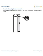
Страница 14: ...he antenna HELLASSAT Point Play Setup Manual page 13 Version 1 2 May 2008 Step 2 Mounting the antenna pole When fixing the antenna pole on the base use a spirit level to make sure the antenna pole sta...

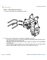
Страница 15: ...ead to the pole If the pole is low enough you can first assemble the masthead brackets and clamps and slide the assembly over the antenna pole If the pole is too high or does not have an open ending y...

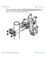
Страница 16: ...l page 15 Version 1 2 May 2008 Make sure the masthead is already pointing in the general direction of the satellite To do so use the pointing data available in the Antenna Pointing Information documen...

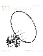
Страница 17: ...Setting up the antenna Version 1 2 May 2008 HELLAS SAT Point Play Setup Manual page 16 3 Attach the dish to the masthead with the appropriate screws and nuts...

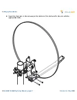
Страница 18: ...Setting up the antenna HELLASSAT Point Play Setup Manual page 17 Version 1 2 May 2008 4 Insert the feed arm in the cut away at the bottom of the dish and fix the arm with the appropriate bolts...

Страница 19: ...tenna Version 1 2 May 2008 HELLAS SAT Point Play Setup Manual page 18 5 Attach the clamp around the iLNB using the appropriate nut and bolt Do not to attach the clamp too tightly as you will need to a...

Страница 20: ...Setting up the antenna HELLASSAT Point Play Setup Manual page 19 Version 1 2 May 2008 6 Slide and click the iLNB clamp into the feed arm...

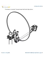
Страница 21: ...Setting up the antenna Version 1 2 May 2008 HELLAS SAT Point Play Setup Manual page 20 The antenna is mounted The result should look like the figure below...

Страница 22: ...Fixing the antenna cabling Fixing the antenna cabling includes the following steps Connecting the F connectors on the coax cable page 22 Grounding the iLNB page 24 Adjusting iLNB polarisation page 25...

Страница 23: ...To connect an F connector to a cable 1 For the outdoor end of the cable first slide the rubber boots over the coax cable 2 Strip the coax cable as shown below Do not remove the aluminium foil or fold...

Страница 24: ...Setting up the antenna HELLASSAT Point Play Setup Manual page 23 Version 1 2 May 2008 5 Screw the F connector to the wire by hand Repeat this procedure for all 4 F connectors 1cm 0 4cm...

Страница 25: ...need to ground the antenna To do so you need a grounding wire for grounding wire specifications see page 9 and a bolt fitting the grounding connection on the masthead The iLNB has a stud that you can...

Страница 26: ...and transmission To adjust iLNB polarisation 1 Check the scaling on the iLNB Depending on the type of iLNB you have the scaling of the iLNB may range from 0 to 180 from 35 to 35 80 90 70 100 60 11 0...

Страница 27: ...etup Manual page 26 2 In the Antenna Pointing Information document look up the value that applies to the city closest to your position 3 Set the iLNB to the angle you have found in the document 4 Lock...

Страница 28: ...x cables these marks are printed on the cables every 50 cm 2 Put the TX and RX connectors in the appropriate RX and TX jacks on the iLNB The outdoor connections need to be waterproof Make sure to use...

Страница 29: ...1 Plug the network cable in the IPmodem s and your computer s ethernet ports You can use the network cable provided in the box or a cable of your choice 2 Use the power adapter provided in the box to...

Страница 30: ...Play Tool page 32 Setting up the Point Play Tool page 33 Rough pointing vertical elevation page 34 Rough pointing horizontal azimuth page 36 Fine pointing the antenna page 39 Checking the antenna poi...

Страница 31: ...d to access the status page of the IPmodem 1 Make sure the IPmodem is turned on and properly connected to your computer with a network cable 2 On your computer start your internet browser for example...

Страница 32: ...e satellite has only one pointing carrier you will see the page below 5 Click the Start Pointing button You can now start pointing the antenna Note Whenever you redo the pointing procedure and access...

Страница 33: ...e The high uninterrupted tone means the antenna points correctly towards the satellite Possible tones are Very low uninterrupted tone The antenna is not pointing to a satellite and has not been pointi...

Страница 34: ...t Play Tool To set up the Point Play Tool 1 Remove the TX connector from the iLNB and connect it to the Point Play Tool 2 Connect the headphone to the appropriate port of the Point Play Tool 3 Make su...

Страница 35: ...you will have to perform these two procedures simultaneously Whenever the procedure tells you to loosen a securing bolt or nut slacken it just enough to allow the corresponding element to move freely...

Страница 36: ...ds each other as shown in the figure above 4 While keeping the eccentric E in this position with the hex key set the dish to the elevation you found in the document Bolt 2 indicates the elevation In t...

Страница 37: ...3 2 Rotate the eccentric 3 with the hex key until the letters A on the eccentric and the masthead point towards each other as shown in the figure above 3 Secure the lock bolts 1 and 2 4 Loosen the bra...

Страница 38: ...horizontally until you hear the highest possible continuous pitch tone Make sure to position the antenna in the middle of this tone range 6 As soon as you hear this continuous high pitch tone secure t...

Страница 39: ...up the antenna The pointing carrier selected in the IPmodem status page is not correct If so on the IPmodem status page on your computer Click Pointing completed Click Restart Pointing Select the othe...

Страница 40: ...r a continuous high pitch tone after securing the bolts the antenna will probably have moved slightly You then need to fine point the antenna Important note The procedures relating to vertical and hor...

Страница 41: ...Setup Manual page 40 Fine pointing vertical 1 Loosen bolt 1 2 Rotate the eccentric 3 until the Point Play Tool produces a continuous high pitch tone 3 Secure bolt 1 4 Place the cap 4 on bolt 2 and se...

Страница 42: ...p Manual page 41 Version 1 2 May 2008 Fine pointing horizontal 1 Loosen the horizontal lock bolt 1 and 2 2 Rotate the eccentric 3 until the Point Play Tool produces a continuous high pitch tone 3 Secu...

Страница 43: ...a is still pointing correctly you will hear the continuous high pitch tone again If not repeat the pointing procedure from the section Rough pointing horizontal azimuth page 36 until you obtain optima...

Страница 44: ...ing is completed you can turn off the Point Play Tool 2 Remove the Tx cable from the Point Play Tool and connect it to the iLNB 3 Slide the rubber boots over the connectors 4 Use tie wraps to attach t...

Страница 45: ...2 May 2008 HELLAS SAT Point Play Setup Manual page 44 Confirming antenna pointing in the software 1 Back to your computer in the status page of the IPmodem click the Pointing Completed button You are...

Отзывы: