background image

Temperature Control System WHS HE

Installation and Operating Instructions

12

 EN

     EN    

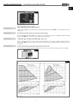
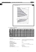
2�9  Calculation of the operating point

In connection with a Helios hot water heating element WHR.., the following guide values for the differential pressure 
setpoint are approximated:

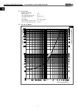
- Technical Data

velocity constant I, II, III

Fig� 16


* The pressure loss in the piping depends on the pipe length, pipe diameter and the water flow rate!

Type
WHR

Water
volume 

Line cross-

section

Press� loss
WHR [kPa]

Press� loss*
pipe [kPa]

Press� loss
WHSH [kPa]

Press� loss
total [kPa] 

Different� press� 

setpoint pump

250

470 l/h

3/4”

8

8

3.5

19.5

2.0 m

315

810 l/h

3/4”

9

8

4.5

21.5

2.2 m

355

1080 l/h

3/4”

9

10

5.5

24.5

2.5 m

400

1060 l/h

3/4”

11

10

5.5

26.5

2.7 m

2/40/20

610 l/h

3/4”

10

8

4

22

2.2 m

4/40/20

980 l/h

3/4”

7

10

5

22

2.2 m

2/50/25-30

1050 l/h

3/4”

7

10

5.5

22.5

2.5 m

4/50/25-30

1680 l/h

1”

5

8

12

25

2.5 m

1420 l/h

1”

8

8

9

25

2.2 m

4/60/30-35

2270 l/h

1”

7

10

20

37

3.7 m

2/70/40

2200 l/h

1”

6

10

20

36

3.6 m

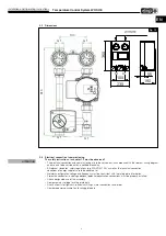
Duct

Pipe

Permitted pumping media (other media on request)

Heating water (pursuant to VDI 2035) water-glycol mix-
tures (max. 1:1; the performance data must be reviewed 
over 20 % admixture) 

Performance

Max. delivery head (Hmax)

6,0 m

Max. flow rate (Qmax)

3,6 m

3

/h

Permitted range of application

Installation location requirements

5 - 50°C < 90% RH non-condensing

Connection voltage

1 ~ 230 V +10 %/ -15 %, 50/60 Hz (as per IEC 60038) 

Protection category

IP X4D

Energy efficiency index EEI

See type plate

Max. operating pressure

10 bar (1000 kPa)

Minimum inlet pressure at  +95 °C/+110 °C

 0.5 bar/ 1.0 bar (50 kPa/ 100 kPa)

Содержание WHS HE

Страница 1: ... Temperature control system Kit de régulation WHS HE Komplettset Complete set Set complet Helios Ventilatoren MONTAGE UND BETRIEBSVORSCHRIFT INSTALLATION AND OPERATING INSTRUCTIONS NOTICE DE MONTAGE ET D UTILISATION DE EN FR ...

Страница 2: ...2 2 Konstruktiver Aufbau Seite 7 2 3 Technische Daten Seite 8 2 4 Druckverlustdiagramm Seite 8 2 5 Abmessungen Seite 9 2 6 Elektrischer Anschluss Inbetriebnahme Seite 9 2 7 Umwälzpumpe Seite 10 2 8 Pumpe einstellen Seite 10 2 9 Ermitteln des Betriebspunktes Seite 12 2 10 Stellantrieb 24V Seite 13 KAPITEL 3 INBETRIEBNAHME SEITE 14 3 1 Erstinbetriebnahme über elektronische Steuereinheit WHSE Seite 1...

Страница 3: ...hes gilt für Haftungsansprüche an Helios Der Gebrach von Zubehörteilen die nicht von Helios empfohlen oder angeboten werden ist nicht statthaft Eventuell auftretende Schäden unterliegen nicht der Gewährleistung Veränderungen und Umbauten am Gerät sind nicht zulässig und führen zum Verlust der Konformität jegliche Gewährleistung und Haftung ist in diesem Fall ausgeschlossen 1 5 Vorschriften Richtli...

Страница 4: ...sperrventile mit Thermometer Vor Rücklauf 2 x Panzerschlauch Edelstahl DN25 1 2 x Reduziernippel Messing 1 1 x Dichtungssatz 1 x WHSE elektronische Steuereinheit 2 x TFK Temperaturfühler Kanalfühler 1 x TFR externer Raumfühler 1 x Montage und Betriebsvorschrift 3 teilige Gehäuseisolierung 1 11 Systemschema WHS HE HINWEIS m WHSH HE 24V Abb 1 Einsetzbar für Helios Warmwasser Heizregister Rohrsystem ...

Страница 5: ...em alle Anlagenkomponenten vollständig verkabelt sind Armaturengruppe immer nur in trockenen und geschlossenen Räumen montieren Vor der Inbetriebnahme ist die Armaturengruppe über einen Potentialausgleich gem gültiger Normen sachgemäß zu erden Sind werksseitig Erdungsanschlüsse vorgegeben müssen diese verwendet werden Nicht zugelassen ist ein Potentialausgleich über Rohrleitungen VDE 0100 540 ist ...

Страница 6: ...ßen Armaturen Im laufenden Betrieb können Teile der Armaturengruppe heiß sein und der ungeschützte Kontakt zu Verbrennungen führen Vor allen Arbeiten Umrüstung Wartung Demontage Heizungsanlage außer Betrieb nehmen und abkühlen lassen Ggf Schutzhandschuhe tragen 1 Die vordere thermische Gehäuseisolierung 1 und den Einlegeblock 2 abziehen 2 Schraube 7 am Wandwinkel 6 lösen 3 Den Vor 3 und Rücklaufst...

Страница 7: ...orlauf links 1 Verschraubung 1 und Schraube 2 lösen 2 Stellmotor 3 abnehmen 3 Deckel 4 und 5 lösen 4 Mischerküken 6 auf die andere Seite montieren 5 Deckel wieder festschrauben und mit einem Drehmoment von 45 Nm anziehen 6 Verdrehsicherung 7 auf die andere Seite umbauen 7 Mischerküken so einstellen dass die Nase des Adapters 6 nach unten zeigt Abb 6 Das Mischerküken verschließt in dieser Stellung ...

Страница 8: ...ebsschalter wieder auf Automatikbetrieb Armaturen Die Verschraubungen sind nach Einbau der Pumpe nachzuziehen Wasseranschluss Beim Anschluss des WHSH ist folgendes zu beachten 1 Der Anschluss des WHSH erfolgt mittels Verschraubungen Zollgewinde 2 Die Anschlussrohre dürfen bei der Mon tage unter keinen Umständen Dreh oder Biege bean spruch ungen ausgesetzt werden Werkzeuge zum Ge gen halten bei der...

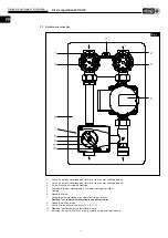
Страница 9: ...ungsschraube Wandwinkel 4 Thermometer zur Anzeige der Vor und Rücklauftemperatur 5 Umwälzpumpe 6 Fächerscheibe 7 Schwerkraftsperre mit Sperrventil 90 Position seitlich unterhalb des 3 Wege Ventil 8 Hintere Wärmedämmschale 9 3 Wege Ventil mit Stellantrieb 24V 0 10V 10 Betriebsstellung Automatik Manuell 11 Drehrichtungsanzeige und Handverstellgriff bei Manuell Einstellung Abb 8 11 1 2 3 5 4 7 8 10 6...

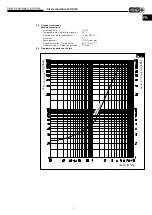
Страница 10: ...kbaugruppe Nenngröße DN 20 max Betriebstemperatur 95 C max Betriebsdruck 10 bar PN10 kvs Wert 5 1 Anschlüsse G1 AG flachdichtend Thermometer Messbereich 0 C 120 C Sperrventil Öffnungsdruck 20 mbar 2 4 Druckverlustdiagramm Druckverlust p mbar Durchfluss V m3 h Druckverlust p kPa W H S H H E Abb 9 ...

Страница 11: ...100 sowie die Technischen Anschlussbedin gungen der Energieversorgungsunternehmen sind unbedingt zu beachten Netzform Spannung und Frequenz müssen mit den Angaben des Leistungsschildes übereinstimmen Schutzleiter einschließlich zusätzlicher Potentialausgleichanschlüsse sind ordnungsgemäß zu installieren Bestimmungsgemäßen Einsatz der Baugruppe überprüfen Netzspannung mit Leistungsschildangabe verg...

Страница 12: ...cktasters ü Die Meldeanzeige ò leuchtet grün im Normalbetrieb Bei Störung leuchtet blinkt sie Logik Stufe 3 2 1 nächster Modus startend mit Stufe 3 Grundeinstellung Auslieferzustand Drehzahlkonstant Stufe 2 Empfohlene Einstellung Differenzdruckkonstant Stufe 2 Startend von Auslieferungszustand 7maliges Drücken des Drucktasters Differenzdruckvariabler Betrieb Die Pumpe regelt sich selbstständig ent...

Страница 13: ...bsstufen ö und des ausgewählten Betriebsmodus ùäë abwechselnd eine Sekunde ein und ausgeschaltet blinken Bei Unterbrechung der Spannungsversorgung bleiben alle Einstellungen Anzeigen gespeichert Manueller Neustart Dauer ca 10 Minuten Halten Sie den Drucktaster ü für 5 Sekunden gedrückt Es blinken nacheinander die LEDs der einzelnen Betriebsstufen ö und Betriebsmodi ùäë Lauflicht Zum Abbrechen des ...

Страница 14: ...0 5 5 24 5 2 5 m 400 1060 l h 3 4 11 10 5 5 26 5 2 7 m 2 40 20 610 l h 3 4 10 8 4 22 2 2 m 4 40 20 980 l h 3 4 7 10 5 22 2 2 m 2 50 25 30 1050 l h 3 4 7 10 5 5 22 5 2 5 m 4 50 25 30 1680 l h 1 5 8 12 25 2 5 m 2 60 30 35 1420 l h 1 8 8 9 25 2 2 m 4 60 30 35 2270 l h 1 7 10 20 37 3 7 m 2 70 40 2200 l h 1 6 10 20 36 3 6 m Kanal Rohr Zulässige Fördermedien andere Medien auf Anfrage Heizungswasser gemä...

Страница 15: ...haltet und ist stromlos Bei Störungen des Regelsy stems kann der Antrieb durch einen zusätzlichen Drehknopf auf Handbetrieb umgestellt werden Technische Daten Betriebsspannung 24V 50 60 Hz Elektr Leistungsaufnahme 2 5 W Schutzklasse II schutzisoliert IP Klasse IP 44 Drehmoment 5 Nm Laufzeit 90 140 s Umgebungstemperatur 0 C 50 C Anschlusskabellänge 2 2 m mit Aderendhülsen Schaltplan SS 954 Abb 17 8...

Страница 16: ...llen Sie die DIP Schalter Pos û 3 und 5 auf Position A und die DIP Schalter 1 2 und 4 auf Position B 2 Drehen Sie das externe Sollwert Poti TFR im Uhrzeigersinn in die Endposition Die LED Y1 Pos á sollte aufleuchten und der Stellantrieb sollte das Drei Wege Ventil öffnen 3 Drehen Sie das externe Sollwert Poti TFR im entgegengesetzten Uhrzeigersinn in die Endposition Die LED Y2 Pos é sollte aufleuc...

Страница 17: ...F Pos ê auf 1 gestellt werden um eine stabile Regelung zu gewährleisten 3 2 Temperaturregelung Das WHS Regelsystem steuert die Vorlauftemperatur zum Warmwasser Heizregister mit Hilfe eines Dreipunkt Ventil stellantriebs Die Steuerung erfolgt durch ein Impuls Pausensignal dessen Verhältnis proportional zur Regelabwei chung ist Nähert sich die zu regelnde Temperatur dem vorgewählten Sollwert so verm...

Страница 18: ... Steuereinheit WHSE arbeitet als Kaskadenregler mit Minimumbegrenzung der Zulufttemperatur Der externe Raum Temperaturfühler TFR wird im Raum angeordnet und ein zusätzlicher Kanal Temperaturfühler TFK wird im Luftkanal nach dem WHR Heizregister eingebaut siehe SS 953 3 Ist die Raumtemperatur höher oder gleich dem eingestellten Sollwert hält der Regler die Zulufttemperatur auf dem ein gestellten Mi...

Страница 19: ...ator aus 25 C Fan off Arrêt ventilateur M 230 Externe Heizkesselsteuerung WHS Regelkombination Fühlervariationen Versorgung Supply Alimentation 230V Sommer Winter Summer Winter Été Hiver 85126 002 SS 953 1 06 06 18 N 230V L 24V zu 24V auf 24V 0 10V 10V 0 10V Haupt Haupt Lüfter an aus ventilateur on off Sollwert Valeur effectif Sommer zu Summer off Été arrêt External ventilation control Commande ve...

Страница 20: ...2 2 Construction design Page 7 2 3 Technical data Page 8 2 4 Pressure loss diagram Page 8 2 5 Dimensions Page 9 2 6 Electrical connection commissioning Page 9 2 7 Circulating pump Page 10 2 8 Adjust pump Page 10 2 9 Calculation of the operating point Page 12 2 10 Actuator 24V Page 13 CHAPTER 3 COMMISSIONING PAGE 14 3 1 Initial commissioning using electronic control unit WHSE Page 14 3 2 Temperatur...

Страница 21: ...arranty shall cease to apply The same applies to liability claims against Helios The use of accessory parts which are not recommended or offered by Helios is not permitted Any possible damages are not covered by the warranty Changes and modifications to the unit are not permitted and lead to a loss of conformity and any warranty and liability shall be excluded in this case 1 5 Certificates Guideli...

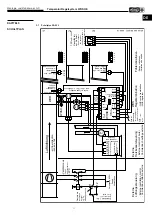
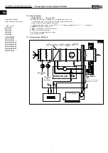
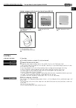
Страница 22: ... x sealing kit 1 x WHSE electronic control unit 2 x TFK temperature sensor duct sensor 1 x TFR external room sensor 1 x Installation and operating instructions 3 part casing insulation 1 11 System diagram WHSH HE WHSH HE 24V warm water heater battery WHR WW heating duct sensor TFK duct sensor TFK anti freeze room sensor TFR only for constant room temperature control Fig 1 Applicable for Helios war...

Страница 23: ...em components are completely wired Only install fitting group in dry and closed rooms The fitting group must be properly grounded via potential equalisation pursuant to applicable standards prior to com missioning If factory grounding specifications are specified they must be used A potential equalisation using piping is not permitted VDE 0100 540 must be observed m Risk of scalding due to hot med...

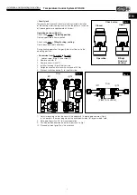
Страница 24: ...ns from hot fittings Fitting group parts can become hot during operation and unprotected contract can cause burns Decommission the heating system and allow it to cool down prior to all work conversion maintenance dismantling Wear protective gloves if necessary 1 Remove the front thermal casing insulation 1 and the insert block 2 2 Loosen screw 7 on wall bracket 6 3 Remove the flow 3 and return lin...

Страница 25: ...left 1 Loosen screw fitting 1 and screw 2 2 Remove actuator 3 3 Remove cover 4 and 5 4 Install mixer plug 6 on the other side 5 Retighten cover and fasten with a torque of 45 Nm 6 Move anti rotation device 7 to the other side 7 Adjust mixer plug so that the nose of the adapter 6 is pointing downwards Fig 6 In this position the mixer plug closes the outlet downwards full bypass mode cold 8 Set oper...

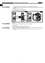
Страница 26: ... to automatic operation Fittings The screw fittings must be retightened after the installation of the pump Water connection When connecting the WHSH the following must be observed 1 The WHSH is connected by means of screw fittings inch thread 2 During assembly the connection pipes must not be exposed to torsional or bending stress under any cir cumstances Use tools to hold in place during assembly...

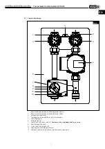
Страница 27: ...ve for the isolation of the heating circuit flow 3 Fixing screw wall bracket 4 Thermometer to indicate flow or return temperature 5 Circulating pump 6 Serrated washer 7 Gravity lock with check valve 90 Position on the side below the 3 way valve 8 Rear heat isolating shell 9 3 way valve with actuator 24V 10 Operating position Automatic Manual 11 Direction indicator and adjustment grip for manual ad...

Страница 28: ... DN 20 max operating temperature 95 C max operating pressure 10 bar PN10 kvs value 5 1 Connections G1 AG flat sealing Thermometer measuring range 0 C 120 C Check valve opening pressure 20 mbar 2 4 Pressure loss diagram Druckverlust p mbar Durchfluss V m3 h Druckverlust p kPa W H S H H E Fig 9 flow rate pressure loss pressure loss ...

Страница 29: ...ons e g DIN VDE 0100 as well as the technical connection conditions of energy suppliers are to be adhered to Network configuration voltage and frequency must be consistent with the rating plate information Protective conductor including additional potential equalisation connections must be properly installed Check designated use of the assembly Compare mains voltage to rating plate data Check all ...

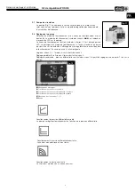
Страница 30: ... The alarm indicator ò lights green in normal operation It lights up flashes in case of a fault Logic Level 3 2 1 next mode starting with level 3 Default setting as delivered state Constant speed level 2 Recommended setting Constant differential pressure level 2 press push button 7 times starting from as delivered state Variable differential pressure operation The pump regulates itself automatical...

Страница 31: ...ating level ö and selected operating mode ùäë LEDs will switch on and off alternately for one second flash If the power supply is interrupted all settings displays remain saved Manual restart duration approx 10 minutes Hold the push button ü down for 5 seconds The individual operating level ö and operating mode ùäë LEDs will flash one after the other running light Hold the push button ü down for 5...

Страница 32: ...0 1060 l h 3 4 11 10 5 5 26 5 2 7 m 2 40 20 610 l h 3 4 10 8 4 22 2 2 m 4 40 20 980 l h 3 4 7 10 5 22 2 2 m 2 50 25 30 1050 l h 3 4 7 10 5 5 22 5 2 5 m 4 50 25 30 1680 l h 1 5 8 12 25 2 5 m 1420 l h 1 8 8 9 25 2 2 m 4 60 30 35 2270 l h 1 7 10 20 37 3 7 m 2 70 40 2200 l h 1 6 10 20 36 3 6 m Duct Pipe Permitted pumping media other media on request Heating water pursuant to VDI 2035 water glycol mix ...

Страница 33: ...rrentless In case of control system failures the drive can be switched to manual operation using an additional rotary encoder Technical data Operating voltage 24V 50 60 Hz Electr power consumption 2 5 W Protection class II protective insulation IP class IP 44 Torque 5 Nm Run time 90 140 s Ambient temperature 0 C 50 C Connecting cable length 2 2 m with wire end ferrules Wiring diagram SS 954 85127 ...

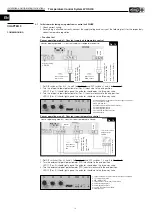
Страница 34: ...etpoint potentiometer TFR counter clockwise to the end position LED Y2 Pos é should light up and the actuator should close the three way valve CHAPTER 3 COMMISSIONING Main Main Mounted directly behind the heating element heated side Both TFK are identical and included in delivery Installation in supply air duct on heated side duct sensor Frost protection duct sensor Main sensor Setpoint setting on...

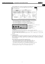
Страница 35: ...es the preset setpoint then the run time of the actuator will reduce and the break time will increase accordingly Three control functions are possible for the temperature control 1 Constant supply air temperature control with a duct temperature sensor TFK 2 Constant room temperature control with an external room temperature sensor TFR 3 Constant room temperature control with a minimum supply air t...

Страница 36: ...e sensor TFR thus a constant room temperature can be achieved Technical data Temperature range 0 30 C Protection class IP 20 Dimensions w x h x d 70 x 70 x 30 mm 3 Constant room air temperature contol with minimum supply air temperature limit The control unit WHSE works as a cascade controller with a minimum supply air temperature limit The external room temperature sensor TFR is located in the ro...

Страница 37: ...larm Ventilator aus 25 C Fan off Arrêt ventilateur M 230 Externe Heizkesselsteuerung WHS Regelkombination Fühlervariationen Versorgung Supply Alimentation 230V Sommer Winter Summer Winter Été Hiver 85126 002 SS 953 1 06 06 18 N 230V L 24V zu 24V auf 24V 0 10V 10V 0 10V Haupt Haupt Lüfter an aus ventilateur on off Sollwert Valeur effectif Sommer zu Summer off Été arrêt External ventilation control ...

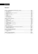
Страница 38: ...truction Page 6 2 3 Données techniques Page 7 2 4 Diagramme de pertes de charge Page 7 2 5 Mesures Page 8 2 6 Raccordement électrique Mise en service Page 8 2 7 Pompe de circulation Page 9 2 8 Réglage de la pompe Page 9 2 9 Détermination des points de fonctionnement Page 11 2 10 Servomoteur 24 V Page 12 CHAPITRE 3 MISE EN SERVICE PAGE 13 3 1 Première mise en service via le régulateur électronique ...

Страница 39: ...gâts causés par cette mauvaise utilisation ne sont pas inclus dans la garantie Les changements et transfor mations de l appareil sont interdites et entraînent une perte de conformité la garantie et la responsabilité du fabricant s annulent 1 5 Réglementations Normes Cet appareil est conforme aux directives CE en vigueur le jour de sa fabrication et sous d une réserve d une utilisation appropriée 1...

Страница 40: ...eu d étanchéité 1 x WHSE régulateur électronique de chauffage 2 x TFK sonde de température sonde de gaine 1 x TFR sonde d ambiance externe 1 x notice de montage et d utilisation Isolation du boîtier en 3 parties 1 11 Systemschema WHS HE REMARQUE m WHSH HE 24V batterie eau chaude WHR Chauffage eau chaude sonde de gaine TFK sonde de gaine TFK antigel sonde d ambiance TFR pour régulation constante de...

Страница 41: ...vigueur Si des raccordements à la terre sont fournis par l usine elles doivent être utilisées La liaison équipotentielle par les gaines n est pas autorisée Les normes VDE 0100 540 et NF C15 100 doivent être respectées m Risque de brûlure en raison de fluides à haute température Lors de travaux sur les conduits pendant le fonctionnement il existe un risque de brûlure si de l eau chaude ou de la vap...

Страница 42: ...tage mural avec des vis ASTUCE Utiliser l isolation interne comme gabarit de perçage 5 Placer la coque d isolation interne 5 sur le support de montage accrocher les conduits départ et retour dans le support mural et fixer avec la plaque d arrêt 8 et vis pour éviter toute déformation 6 À la fin du montage assurer le raccordement hydraulique 7 Remettre le bloc intercalé 2 et la coque d isolation en ...

Страница 43: ... pas forcer Tourner la molette de sélection manuelle en sens anti horaire jusqu à la butée La flèche de la molette de sélection manuelle se trouve dans la zone bleue 11 Mettre le servomoteur dans l axe du mélangeur de voie 12 Visser 2 avec la rondelle insérée et bien serrer 13 Remettre l interrupteur en mode automatique Armatures Les vissages sont à resserrer après le montage de la pompe Raccordem...

Страница 44: ...chauffage départ 3 Vis de fixation pour support montage 4 Thermomètre pour affichage de la température départ et retour 5 Pompe 6 Rondelle insérée 7 Verrouillage thermosiphon avec clapet anti retour avec 90 Position sur le dessous latéral de la vanne trois voies 8 Coque d isolation interne 9 Vanne 3 voies avec servomoteur 24 V 0 10 V 10 Mode de fonctionnement automatique manuel 11 Indicateur du se...

Страница 45: ...e fonctionnement 95 C Pression max de fonctionnement 10 bar PN10 Valeur Kvs 5 1 Raccordements G1 AG joint plat Plage de mesures Thermomètre de 0 C à 120 C Clapet anti retour Retour de pression 20 mbar 2 4 Diagramme de pertes de charge Fig 9 Druckverlust p mbar Durchfluss V m3 h Druckverlust p kPa W H S H H E perte de charge perte de charge débit ...

Страница 46: ...nisseurs d énergies Forme de réseau tension et fréquence doivent correspondre aux données techniques indiquées sur la plaque signalétique du modèle Le conducteur de protection y compris les raccords d équipotentialité sont à installer obligatoirement Veiller à utiliser le produit dans des conditions normales Comparer la tension de réseau avec celle indiquée sur la plaque signalétique Vérifier que ...

Страница 47: ...de message ò s allume en vert pendant le fonctionnement En cas de panne il s allume clignote Logique niveau 3 2 1 mode suivant à partir du niveau 3 Réglage par défaut à la livraison vitesse constante niveau 2 Réglage recommandé pression différentielle constante de niveau 2 à partir du réglage usine appuyer 7 fois sur le bouton Fonctionnement à pression différentielle variable La pompe se régule au...

Страница 48: ... ö et du mode de fonctionnement sélectionné ùäë sont alternativement allumées et éteintes pendant une seconde clignotantes Si l alimentation électrique est interrompue tous les réglages affichages sont enregistrés Redémarrage manuel durée environ 10 minutes Maintenir le bouton ü enfoncé pendant 5 secondes Les LEDs des diffé rents niveaux de fonctionnement ö et des modes de fonctionnement ùäë clign...

Страница 49: ...2 5 m 400 1060 l h 3 4 11 10 5 5 26 5 2 7 m 2 40 20 610 l h 3 4 10 8 4 22 2 2 m 4 40 20 980 l h 3 4 7 10 5 22 2 2 m 2 50 25 30 1050 l h 3 4 7 10 5 5 22 5 2 5 m 4 50 25 30 1680 l h 1 5 8 12 25 2 5 m 2 60 30 35 1420 l h 1 8 8 9 25 2 2 m 4 60 30 35 2270 l h 1 7 10 20 37 3 7 m 2 70 40 2200 l h 1 6 10 20 36 3 6 m Gaine Tuyau Liquides autorisés autres fluides sur demande Eau de chauffage conforme à la n...

Страница 50: ...e défaut du système de régulation la commande peut être effectuée via un bouton de commande manuel additionnel Données techniques Plage de tension en utilisation 24 V 50 60 Hz Puissance 2 5 W Protection II isolé Classe IP IP 44 Couple 5 Nm Durée 90 140 s Plage de température 0 C 50 C Long du câble de raccordement 2 2 m avec embout Schéma de raccordement SS 954 Fig 17 85127 001 SS 954 03 12 09 24V ...

Страница 51: ...servomoteur doit fermer la vanne 3 voies CHAPITRE 3 MISE EN SERVICE Principal Principal Installation dans le con duit d air soufflé en aval côté soufflage Les deux TFK sont identiques et font partie du contenu de la livraison Installation dans le conduit d air soufflé en aval côté soufflage Sonde de gaine TFK antigel Sonde de gaine TFK principale Réglage du point de consigne sur WHSE Fig 18 Mode d...

Страница 52: ... sonde de température ambiante externe TFR 3 Régulation à température ambiante constante avec limite basse de la température de l air soufflé Avec sonde de température ambiante externe TFR et sonde de température de gaine supp TFK Les trois circuits de régulation sont à équiper d une sonde température anti gel TFK derrière le WHR voir schéma de raccordement SS 953 page 17 et le schéma du système p...

Страница 53: ...ture de soufflage Le régulateur électronique de chauffage WHSE fonctionne tel un régulateur de proportionnalité avec une limite min de la température de soufflage La sonde de température externe TFR sera placée dans la pièce et une sonde de température de gaine additionnelle TFK sera montée après la batterie de chauffe WHR voir SS 953 3 Si la valeur de la température ambiante est plus élevée ou id...

Страница 54: ... Ventilator aus 25 C Fan off Arrêt ventilateur M 230 Externe Heizkesselsteuerung WHS Regelkombination Fühlervariationen Versorgung Supply Alimentation 230V Sommer Winter Summer Winter Été Hiver 85126 002 SS 953 1 06 06 18 N 230V L 24V zu 24V auf 24V 0 10V 10V 0 10V Haupt Haupt Lüfter an aus ventilateur on off Sollwert Valeur effectif Sommer zu Summer off Été arrêt External ventilation control Comm...

Страница 55: ...chtlinie gefährliche Stoffe in Elektro und Elektronikgeräten 2011 65 EU Angewandte harmonisierte Normen Applied harmonised standards Normes harmonisées appliquées Angewandte nationale Normen und technische Spezifikationen Applied national standards and technical specifications Normes nationales appliquées et spécifications techniques Ferner erklären wir dass die speziellen technischen Unterlagen f...

Страница 56: ...on D HELIOS Ventilatoren GmbH Co KG Lupfenstraße 8 78056 VS Schwenningen F HELIOS Ventilateurs Le Carré des Aviateurs 157 av Charles Floquet 93155 Le Blanc Mesnil Cedex CH HELIOS Ventilatoren AG Tannstrasse 4 8112 Otelfingen GB HELIOS Ventilation Systems Ltd 5 Crown Gate Wyncolls Road Severalls Industrial Park A HELIOS Ventilatoren Postfach 854 Siemensstraße 15 6023 Innsbruck Colchester Essex CO4 ...

Отзывы: