EN
15
Fresh Air Boxes – ALB EC
Installation and Operating Instructions
CHAPTER 8
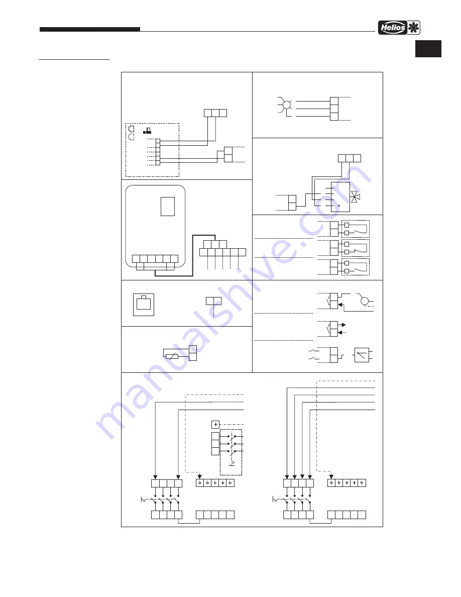
WIRING DIAGRAMS
ALB EC /
accessory components
Wiring diagram SS-1251
■
Main s
witc
h
■
W
ater
pump
■
Boost
mode
■
Exter
-
nal switc
h
■
Fire
contact
■
Outdoor
air flap
■
Main s
witc
h
ALB EC 60/35
WW
:
5x1.5mm²,
1.9A,
400V~
ALB EC 80/50
WW
:
5x1.5mm²,
2.9A,
400V~
N'
N'
N'
N'
N'
N'
N'
N'
N'
N'
CANH
CANL
■
Contr
ol panel
+12V
B
SD
A
GND
25
26
27
28
29
30
CANH
CANL
+12V
B
A
GND
(WHSH)
13
17
15
14
18
16
N
N
L
N
N
N
N
L3
L3
L2
L2
L1
L1
L1
PE
L
PE
L
L
PE
■
P
otential free
7
8
5
6
L2F
L1F
11
12
M
■
F
an run
indication
N.C
max.
40m
250V~
max.
2A
A
C1
250V~
max.
2A
A
C1
max.
0.1A,
20V
A
max.
0.1A,
20V
A
L-open 230V~
■
Mixing v
alve
24V~/ 0-10V=
~
~
+
0-10V
U
1
2
3
5
0-10V
GND
19
20
(WHSH)
KWL-CO
,
Ar
t.Nr
. 4272
2
KWL-FTF
,
Ar
t.Nr
. 4273
KWL-V
OC
,
Ar
t.Nr
. 4274
15-24V~
/ 24V=
A1
GND
~
~
+
-
A2
GND
EXT
■
Air quality sensor
24V+
24V+
12V+
12V+
GND
GND
■
T
erminal
■
T
erminal
■
Extract air fan
44
43
GND
0-10
CO2
+
85499 015 SS-1251 11.06.18 S
.2
32
33
31
GND
0-10
GND
0-10V
M
PE
N
L
max.
20m
max.
20m,
max.
10mA
RPM
RPM
■
Modb
us
25
26
B
RS485
A
TCP
■
T
emperature
sensor r
oom
56
55
Room
GND
NTC 10k
If not used:
connect 32-33
ALB EC 40/20
WW
:
3x1.5mm²,
1.1A,
230V~
ALB EC 50/30
WW
:
3x1.5mm²,
2.9A,
230V~
ALB EC 30/20 EH: 3 x 1.5mm²,
0.9A,
230V~
+ electrical heater
L1
L1
L2
L2
PE
L3
L3
■
T
o be
estab
lished
on
site
Electrical heater: ALB EC EH 30/20
4 x 1.5mm²,
9.5A,
400V~
Содержание ALB EC 30/20 EH
Страница 23: ...21 Außenluft Boxen ALB EC Montage und Betriebsvorschrift DE ...
Страница 45: ...21 Fresh Air Boxes ALB EC Installation and Operating Instructions EN ...
Страница 46: ...22 Fresh Air Boxes ALB EC Installation and Operating Instructions ...
Страница 47: ...23 Fresh Air Boxes ALB EC Installation and Operating Instructions ...


