background image

2

Fresh Air Boxes – ALB EC

Installation and Operating Instructions

•  Only transport fans using means of transport that are appropriate for the weight,  

wear protective gloves during transport!

•  Wear protective gloves/footwear when unpacking the unit.

•  Ensure the suitable load capacity and properties of the mounting surface and 

use suitable mounting material.

•  The operator is responsible for observing all plant-related safety regulations!

•  Abnormally frequent activation/deactivation is not permissible.

•  Once the rotating parts come to a standstill, a waiting time of 5 min. must be 

observed, as dangerous voltages may be present due to internal capacitors 

even after disconnection from the mains.

•  Protection against contact for the impeller must be ensured pursuant to DIN 

EN 13857.

•  The planner and operator must ensure easy access for inspection and cleaning 

work!

•  A uniform inflow and free outlet must be ensured.

•  When using vented fire places in a ventilated room, there must be sufficient supply 

air for all operating conditions (consult chimney sweep).

Frost protection information (only ALB EC WW)

ALB EC WW fresh air boxes have a warm water heater battery. In order to avoid 

frost damage, heating water must always be available. The heating system must 

be always in operation even if the ventilation system is turned off. In order to 

guarantee that no cold outside air below +5 °C arrives at the heat exchanger, 

an external damper must always be integrated in the ventilation system.

1 .3  Area of application

– Normal use

The ALB EC fresh air box is designed specifically for direct installation in ventilation channel/duct systems and for ver-
satile commercial applications. The units are suitable for the use in dry interior rooms at temperatures from +5 °C to 
+35 °C. They are suitable for moving clean air without dust, grease, chemical evaporation and other pollution.

- Max. relative humidity: 80 %
- Electrical protection class: IP20
- Max. intake temperature without 40 °C
- Max. intake temperature with 20 °C

The units are designed only for installation in frost-protected rooms. Frost and water damages may occur if installed  
outdoors.

– Reasonably foreseeable misuse

The ALB EC fresh air box is not suitable for operation under difficult conditions, such as high levels of humidity, aggres-
sive media, heavy contamination, excessive loads due to climatic, technical or electronic influences. It is not intended 
for use in a mobile unit (e.g. motor vehicles, aircraft, ships, etc.).

– Improper, prohibited use

Outdoor installation or in direct contact with water. Conveyance of explosive gas mixtures/media. Installation in an ex-
plosive area/atmosphere. Operation without standardised safety devices (e.g. protective grille). Conveyance of solids or 
liquids. Conveyance of abrasive and/or fan material-corrosive media. Conveyance of conveyed medium containing fat.

1 .4 Boundaries

Spatial

A straight, flat pipe section of 500 mm must be ensured before and after the unit. When using a pipeline at the start,
the air inlets must be equipped with a shutter (RSK, RVM (accessories)). When using a pipeline at the end, a protection 
grille must be used on the outlet side.


The outlet-side environment must not be accessible to unauthorised persons and obstructed.


The fan must be easily accessible for cleaning and maintenance purposes, particularly the terminal box.

Power supply interface

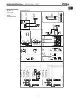
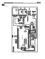
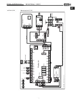
Connection only with permanently installed lines according to wiring diagram.

m


ALB EC WW

    EN    

Содержание ALB EC 30/20 EH

Страница 1: ...Außenluft Boxen Fresh Air Boxes ALB EC 30 20 EH 40 20 WW 50 30 WW 60 35 WW 80 50 WW EN Helios Ventilatoren MONTAGE UND BETRIEBSVORSCHRIFT INSTALLATION AND OPERATING INSTRUCTIONS DE ...

Страница 2: ...e 10 6 1 Montage Einbau Abhängepunkte Seite 10 6 2 Elektrischer Anschluss Seite 11 6 3 Anschluss Warmwasser Heizregister Seite 12 6 4 Anschluss externer Komponenten Seite 12 6 5 Inbetriebnahme Seite 12 6 6 Betrieb Seite 13 KAPITEL 7 INSTANDHALTUNG UND WARTUNG Seite 13 7 0 Instandhaltung und Wartung Seite 13 7 1 Filterwechsel Seite 13 7 2 Reinigung Seite 13 7 3 Ersatzteile Seite 13 7 4 Stilllegen u...

Страница 3: ...e Ketten oder sonstigen Schmuck tragen n Schutzhandschuhe SchutzhandschuhedienenzumSchutzderHändevorReibung Abschürfungen Einstichen oder tieferen Verletzungen sowie vor Berührung mit heißen Oberflächen m Sicherheitsschuhe Sicherheitsschuhe dienen zum Schutz vor schweren herabfallenden Teilen und verhindern Ausrutschen auf rutschigem Untergrund Haarnetz Das Haarnetz dient vorwiegend zum Schutz vor...

Страница 4: ... und für vielseitige Anwendungen im Gewerbebereich vorgesehen Die Geräte sind für den Einsatz in trockener Innenumgebung im Temperaturbereich von 5 C bis 35 C bestimmt Sie eignen sich für den Transport von reiner Luft ohne Staub Fett chemischer Verdunstung und anderen Verunreinigungen Max relative Luftfeuchtigkeit 80 Elektrische Schutzart IP20 Max Ansaugtemperatur ohne Heizung 40 C Max Ansaugtempe...

Страница 5: ...lle Motoren sind mit Thermokontakten ausgestattet die von der Motorsteuerung überwacht werden und selbsttätig aus und nach erfolgter Abkühlung wieder einschalten 1 9 Frostschutz nur ALB EC WW Die Außenluft Box ALB EC WW ist mit einem Warmwasser Heizregister ausgestattet Um das Warmwasser Heizregister vor dem Einfrieren zu schützen und Wasserschäden zu vermeiden ist im Lieferumfang eine Frostschutz...

Страница 6: ...ll auftretende Schäden unterliegen nicht der Gewährleistung Veränderungen und Umbauten am Gerät sind nicht zulässig und führen zum Verlust der Konformität jegliche Gewährleistung und Haftung ist in diesem Fall ausgeschlossen 2 1 Vorschriften Richtlinien Bei ordnungsgemäßer Installation und bestimmungsgemäßem Betrieb entspricht das Gerät den zum Zeitpunkt seiner Herstellung gültigen Vorschriften un...

Страница 7: ...etriebsbedingungen etc können zu einer Erhöhung der angegebenen Katalog Werte führen Angaben die sich auf bestimmte Abstände 1 2 4 m beziehen gelten für Freifeldbedingungen Der Schalldruckpegel kann im Einbaufall erheblich von der Katalogangabe abweichen da er stark von den Einbaugegebenheiten d h vom Absorptionsvermögen des Raumes der Raumgröße u a Faktoren abhängig ist 3 0 Technische Daten Die t...

Страница 8: ...50 WW 6 Außenluft Boxen ALB EC Montage und Betriebsvorschrift DE 353 125 78 133 472 850 2 x G 1 322 341 522 541 620 317 100 4xM 8 min 620 ø8 57 5 57 5 57 5 57 5 Alle Maße in mm ALB EC 50 30 WW 353 125 850 117 133 2 x G 1 548 4 x M 8 372 622 390 640 718 317 100 min 718 ø8 57 5 57 5 57 5 57 5 Alle Maße in mm ALB EC 60 35 WW ...

Страница 9: ...itprogramm durch antippen eingestellt werden Über den Button ADD können neue Zeitintervalle hinzugefügt werden Benutzersicherung Bei eingestellter Benutzersicherung muss das Gerät durch die Eingabe eines Zahlencodes entsperrt werden s Einstellungen Servicemenü 23 Benutzersicherung Ventilator Einstellung der Sollwert Ventilatorleistung ù von 20 100 Anzeige der aktuellen Ventilatorleistung ò Tempera...

Страница 10: ...eizregisters Ohne Wasser Elektrisch 08 AQS Sensor Einstellung des Air Quality Sensors Luftqualitätssensor Angeschlossen am Analogeingang Klemme 43 44 ohne CO2 0 2000 ppm tiefere Werte als 200 ppm 1 V werden als Sensorfehler erkannt CO2 0 1100 ppm tiefere Werte als 200 ppm 1 V werden als Sensorfehler erkannt RH Feuchtesensor 0 100 0 10 V VOC Sensor 0 100 0 10 V Ext 0 10 V Luftqualitätsprüfung Atmun...

Страница 11: ... Freecooling Einstellung der freien Nachtkühlung Es kann der Volumenstrom 50 100 während der freien Nachtkühlung sowie die Mindesttemperatur 12 25 C eingestellt werden 17 PID Parametrierung Die im Gerät installierten Heizregister werden angezeigt Für diese können die PID Parameter eingestellt werden P 50 60 C I 1 255 s D 0 10 Min 18 HW Test Ventilator Heizregister Luftklappen und Relais lassen sic...

Страница 12: ...len laut Abb 2 zulässigen Positionen möglich Für Filterreinigung austausch und Service auf gute Gerätezugänglichkeit achten Das Gerät kann direkt in den Kanal die Rohrleitung montiert werden Bei Bedarf ist der Körperschallübertragung durch Verwendung von Schwingungsdämpfern und Segeltuchstutzen entgegenzuwirken s Zubehör Eine ausreichend lange gerade Rohrstrecke 500 mm vor und hinter dem Gerät ist...

Страница 13: ... Typenschilds übereinstimmen Bei Montage der elektrischen Zuleitungen ist zu beachten dass bei Wasserbeaufschlagung kein Eindringen entlang der Leitungen möglich ist Zur Montage der Anschlusskabel dienen die seitlichen Durchführungen im Klemmenkasten Bei Durchführung der Kabel ist darauf zu achten dass die elektrische Schutzart erhalten bleibt Klemmenbezeichnungen entsprechen dem Anschlussplan im ...

Страница 14: ... nach der Montage angeschlossen müssen ihre Enden isoliert werden Weitere externe Komponenten gemäß Anschlussplan anschließen Abluftventilator Anschluss gemäß Anschlussplan Falls kein RPM Signal vom Ventilator zur Verfügung steht muss eine Verbindung zwischen Klemme 32 GND und Klemme 33 RPM hergestellt werden 6 5 Inbetriebnahme m WARNUNG Das drehende Laufrad kann Ihre Finger quetschen abschürfen V...

Страница 15: ...stechnisch wichtige Funktion übernimmt ist eine einsatzabhängige regelmäßige Wartung erforderlich Im Falle längeren Stillstands ist bei Wiederinbetriebnahme eine Wartung durchzuführen Zu prüfen sind Sichere Befestigung der ALB am Untergrund an der Anlage im Zweifelsfall erneuern Schmutzablagerungen entfernen siehe Reinigung Kapitel 7 2 Mechanische Beschädigungen Gerät stilllegen beschädigte Teile ...

Страница 16: ...Ggf einen Funktionstest mit dem Sensor mithilfe der Widerstandsmessung durchführen der Widerstandswert bei 20 C be trägt etwa 10 kΩ 24 Fehler am Temperatursensor Wasserrückluaf T_WATER_OUT Gerät funktioniert nicht Fehler am Temperatursensor Kontrollieren ob der Sensor richtig an die Elektronik angeschlossen ist Ggf einen Funktionstest mit dem Sensor mithilfe der Widerstandsmessung durchführen der ...

Страница 17: ...L2 L2 L1 L1 L1 L1 L1 L2 L2 PE L PE PE L L PE Potentialfrei 7 8 5 6 L2F L1F 11 12 M Betriebs meldung Ventilato ren N C max 40m 250V max 2A AC1 250V max 2A AC1 max 0 1A 20VA max 0 1A 20VA L open 230V Mischerventil 24V 0 10V 0 10V U 1 2 3 5 0 10V GND 19 20 WHSH KWL CO Art Nr 4272 2 KWL FTF Art Nr 4273 KWL VOC Art Nr 4274 15 24V 24V A1 GND A2 GND EXT Luftqualitätssensor 24V 24V 12V 12V GND GND Anschlu...

Страница 18: ...1 22 23 24 PWM RPM PWM WAT OUT Ext3 Ext2 Ext1 CO2 PE DC12V L N L Fu I BUS I BUS I BUS 3 15A T SSR 40A 1 4 3 2 SSR 40A 1 4 3 2 3x2 3kW A2 A1 N N LF N L1 Reset 115 C 115 C 50 C 50 C Reset 20A Filter 3x1 5mm 0 9A 230V 4x1 5mm 9 5A 400V M PE N L N N N N L F 12V N 3 7 4 8 I BUS INPUT Bedienteil Volumenstrom überwachung RD OR Hauptschalter L1 L2 L3 N L1F L2F LF 60 62 57 YE BU WH V2 24VDC HF30W DDR A V1 ...

Страница 19: ... 10 11 12 13 14 15 16 17 18 19 20 21 22 23 24 PWM RPM WAT OUT Ext3 Ext2 Ext1 CO2 PE DC12V L N L Fu L2F I BUS I BUS I BUS 3 15A T N L1 3x1 5mm 1 1A 230V LF 60 Wasserrücklauf blau N N N N 62 57 L F 12V N 3 7 4 8 I BUS INPUT GND RPM PWM N LF M PE N L YE BU WH Bedienteil Hauptschalter Zuluftventilator Zuluft grün Vorheizung rot Außenluft schwarz Relais Sicherung Platine A1 Sicherung Ventilator L1 L2 L...

Страница 20: ... 0 10 8 9 10 11 12 13 14 15 16 17 18 19 20 21 22 23 24 PWM RPM WAT OUT Ext3 Ext2 Ext1 CO2 PE DC12V L N L Fu I BUS I BUS I BUS 3 15A T N L1 3x1 5mm 2 9A 230V N N N N L F 12V N 3 7 4 8 I BUS INPUT A 0 BCD B 12V GND GND TK TK PWM N LF M PE N L GN L1 L2 L3 N L1F L2F LF 60 62 57 YE BU WH WH V2 24VDC HF30W DDR A V1 12VDC NTC 10k NTC 10k NTC 10k NTC 10k BU GN OR WH GN 85499 010 SS 1246 12 10 17 S 1 Bedie...

Страница 21: ... GND 0 10 8 9 10 11 12 13 14 15 16 17 18 19 20 21 22 23 24 PWM RPM WAT OUT Ext3 Ext2 Ext1 CO2 PE DC12V L N L Fu I BUS I BUS I BUS 5A T 5A T 5A T N L1 5x1 5mm 1 9A 400V N N N N L F 12V N 3 7 4 8 I BUS INPUT GND COM NC 0 10V L3F M PE L3 L2 L1 RD L2F L1F GN L1 L2 L3 N L1F L2F L1F L2F L3F 60 62 57 BU WH V2 24VDC HF30W DDR A V1 12VDC NTC 10k NTC 10k NTC 10k NTC 10k BU GN OR WH GN 85499 012 SS 1248 12 1...

Страница 22: ... GND GND COM NC 0 10 8 9 10 11 12 13 14 15 16 17 18 19 20 21 22 23 24 PWM RPM 0 10V WAT OUT Ext3 Ext2 Ext1 CO2 PE DC12V L N L Fu I BUS I BUS I BUS 5A T 5A T 5A T N L3F L1 5x1 5mm 2 9A 400V M PE L3 L2 L1 N N N N L F 12V N 3 7 4 8 I BUS INPUT L2F L1F GN L1 L2 L3 N RD L1F L2F L1F L2F L3F 60 62 57 BU WH V2 24VDC HF30W DDR A V1 12VDC NTC 10k NTC 10k NTC 10k NTC 10k BU GN OR WH GN 85499 014 SS 1250 12 1...

Страница 23: ...21 Außenluft Boxen ALB EC Montage und Betriebsvorschrift DE ...

Страница 24: ...ISSIONING Page 10 6 0 Design Page 10 6 1 Installation Installation suspension points Page 10 6 2 Electrical connection Page 11 6 3 Connection of warm water heater battery Page 12 6 4 Connection of external components Page 12 6 5 Commissioning Page 12 6 6 Operation Page 13 CHAPTER 7 SERVICING AND MAINTENANCE Page 13 7 0 Servicing and maintenance Page 13 7 1 Filter change Page 13 7 2 Cleaning Page 1...

Страница 25: ...wear rings chains or other jewellery n Protective gloves Protective gloves serve to protect the hands against rubbing abrasions cuts or more profound injuries as well as contact with hot surfaces m Protective footwear Protective footwear serves to protect against heavy falling parts and from slip ping on slippery surfaces Hair net The hair net primarily serves to protect long hair against contact ...

Страница 26: ...ems and for ver satile commercial applications The units are suitable for the use in dry interior rooms at temperatures from 5 C to 35 C They are suitable for moving clean air without dust grease chemical evaporation and other pollution Max relative humidity 80 Electrical protection class IP20 Max intake temperature without heater 40 C Max intake temperature with heater 20 C The units are designed...

Страница 27: ...ll motors have thermal contacts which are wired in series with the coil and switch off automatically and restart after cooling 1 9 Frost protection only ALB EC WW The ALB EC WW fresh air box is equipped with a warm water heater battery In order to protect the warm water heater battery against freezing and to prevent water damage an automatic frost protection mechanism is included in the scope of d...

Страница 28: ...ainst Helios The use of accessory parts which are not recommended or offered by Helios is not permitted Any possible damages are not covered by the warranty Changes and modifications to the unit are not permitted and lead to a loss of conformity and any warranty and liability shall be excluded in this case 2 1 Regulations Guidelines If the product is installed correctly and used to its intended pu...

Страница 29: ...r things can lead to an increase in the specified catalogue values Data that refers to certain distances 1 2 4 m apply to free field conditions With regard to installation the sound pressure level can differ significantly from the catalogue data as it is highly dependent on the installation conditions i e on the absorption capability of the room the room size among other factors 3 0 Technical data...

Страница 30: ...W 6 Fresh Air Boxes ALB EC Installation and Operating Instructions EN 353 125 78 133 472 850 2 x G 1 322 341 522 541 620 317 100 4xM 8 min 620 ø8 57 5 57 5 57 5 57 5 All dim in mm ALB EC 50 30 WW 353 125 850 117 133 2 x G 1 548 4 x M 8 372 622 390 640 718 317 100 min 718 ø8 57 5 57 5 57 5 57 5 All dim in mm ALB EC 60 35 WW ...

Страница 31: ...esponding time blocks weekly or time programme can then be set by tapping New time intervals can be added using the ADD button User lock When the user lock is set the unit must be unlocked by entering a numerical code see Settings Service menu 23 User lock Fan Set the setpoint fan power ù from 20 100 Displays the current fan power ò Temperature Set the setpoint temperature ù in the range from 15 4...

Страница 32: ... sensor errors CO2 0 1100 ppm values lower than 200 ppm 1 V are detected as sensor errors RH humidity sensor 0 100 0 10 V VOC sensor 0 100 0 10 V Ext 0 10 V Air quality test respiration The function is available when an Air Quality Sensor CO2 sensor humidity sensor is installed in the extract air duct or directly in the unit This is only available with the optional AQS duct sensor upon request If ...

Страница 33: ...ked 16 Freecooling Set the free night cooling The flow rate 50 100 during Free night cooling and the minimum temperature 12 25 C can be adjusted 17 PID parametrisation The heater batteries installed in the unit are displayed The PID parameters for these can be adjusted P 50 60 C I 1 255 s D 0 10 min 18 HW test The fan heater battery air shutter and relay can be manually tested Upon activation of t...

Страница 34: ...it can be installed in all positions permitted in Fig 2 Ensure good accessibility for filter changes replacement and service The unit can be directly installed in the duct piping If required the structure borne sound transmission can be coun teracted by using vibration dampers and canvas connection pieces see accessories There is a sufficiently long straight section of pipe 500 mm before and after...

Страница 35: ...s in case of water exposure Bushings on the side of the terminal box are to be used for entry of connecting cables The cables must be put through the bushings ensuring the electrical protection class is maintained Terminal markings correspond to the wiring diagram in the terminal box When connecting all connectors in the terminal box it is necessary to ensure that damage is not caused Connection o...

Страница 36: ...tallation its ends must be isolated Connect other external components in accordance with wiring diagram Extract air fan Connect in accordance with wiring diagram If there is no RPM signal from the fan a connection must be established between terminal 32 GND and terminal 33 RPM 6 5 Commissioning m WARNING The rotating impeller can crush scrape fingers Ensure protection against contact before commis...

Страница 37: ... unit must be cleaned If the fan has an important supply function regular performance related maintenance is necessary In cases of longer periods of standstill maintenance must be carried out when the unit is restarted The following should be checked Secure mounting of the ALB on subsurface on the system Replace in case of doubt Dirt deposits Remove see Cleaning Chapter 7 2 Mechanical damage Decom...

Страница 38: ... resistance measurement if necessary the resistance value at 20 C is around 10 kΩ 24 Error concerning water return temperature sensor T_WATER_OUT Unit does not function Temperature sensor error Check whether the sensor is correctly connected to the electronics Carry out a function test with the sensor by means of resistance measurement if necessary the resistance value at 20 C is around 10 kΩ 25 E...

Страница 39: ...40m 250V max 2A AC1 250V max 2A AC1 max 0 1A 20VA max 0 1A 20VA L open 230V Mixing valve 24V 0 10V 0 10V U 1 2 3 5 0 10V GND 19 20 WHSH KWL CO Art Nr 4272 2 KWL FTF Art Nr 4273 KWL VOC Art Nr 4274 15 24V 24V A1 GND A2 GND EXT Air quality sensor 24V 24V 12V 12V GND GND Terminal Terminal Extract air fan 44 43 GND 0 10 CO2 85499 015 SS 1251 11 06 18 S 2 32 33 31 GND 0 10 GND 0 10V M PE N L max 20m ma...

Страница 40: ...8 19 20 21 22 23 24 PWM RPM PWM WAT OUT Ext3 Ext2 Ext1 CO2 PE DC12V L N L Fu I BUS I BUS I BUS 3 15A T SSR 40A 1 4 3 2 SSR 40A 1 4 3 2 3x2 3kW A2 A1 N N LF N L1 Reset 115 C 115 C 50 C 50 C Reset 20A 3x1 5mm 0 9A 230V 4x1 5mm 9 5A 400V M PE N L N N N N L F 12V N 3 7 4 8 I BUS INPUT RD OR L1 L2 L3 N L1F L2F LF 60 62 57 YE BU WH V2 24VDC HF30W DDR A V1 12VDC BU BU GN GN OR OR WH GN WH GN NTC 10k NTC ...

Страница 41: ...10 8 9 10 11 12 13 14 15 16 17 18 19 20 21 22 23 24 PWM RPM WAT OUT Ext3 Ext2 Ext1 CO2 PE DC12V L N L Fu L2F FUSE I BUS I BUS I BUS 3 15A T RELAY RELAY RELAY RELAY RELAY N L1 3x1 5mm 1 1A 230V LF 60 water outlet blue N N N N 62 57 L F 12V N 3 7 4 8 I BUS INPUT GND RPM PWM N LF M PE N L YE BU WH Control panel Main switch Supply fan supply green preheater red outdoor air black Electronic board A1 Fu...

Страница 42: ... GND 0 10 8 9 10 11 12 13 14 15 16 17 18 19 20 21 22 23 24 PWM RPM WAT OUT Ext3 Ext2 Ext1 CO2 PE DC12V L N L Fu I BUS I BUS I BUS 3 15A T N L1 3x1 5mm 2 9A 230V N N N N L F 12V N 3 7 4 8 I BUS INPUT A 0 BCD B 12V GND GND TK TK PWM N LF M PE N L GN L1 L2 L3 N L1F L2F LF 60 62 57 YE BU WH WH V2 24VDC HF30W DDR A V1 12VDC NTC 10k NTC 10k NTC 10k NTC 10k BU GN OR WH GN 85499 010 SS 1246 12 10 17 S 1 B...

Страница 43: ...GND GND GND 0 10 8 9 10 11 12 13 14 15 16 17 18 19 20 21 22 23 24 PWM RPM WAT OUT Ext3 Ext2 Ext1 CO2 PE DC12V L N L Fu FUSE I BUS I BUS I BUS 5A T 5A T 5A T RELAY RELAY RELAY RELAY RELAY N L1 5x1 5mm 1 9A 400V N N N N L F 12V N 3 7 4 8 I BUS INPUT GND COM NC 0 10V L3F M PE L3 L2 L1 RD L2F L1F GN L1 L2 L3 N L1F L2F L1F L2F L3F 60 62 57 BU WH V2 24VDC HF30W DDR A V1 12VDC NTC 10k NTC 10k NTC 10k NTC...

Страница 44: ...GND GND GND GND COM NC 0 10 8 9 10 11 12 13 14 15 16 17 18 19 20 21 22 23 24 PWM RPM 0 10V WAT OUT Ext3 Ext2 Ext1 CO2 PE DC12V L N L Fu FUSE I BUS I BUS I BUS 5A T 5A T 5A T RELAY RELAY RELAY RELAY RELAY N L3F L1 5x1 5mm 2 9A 400V M PE L3 L2 L1 N N N N L F 12V N 3 7 4 8 I BUS INPUT L2F L1F GN L1 L2 L3 N RD L1F L2F L1F L2F L3F 60 62 57 BU WH V2 24VDC HF30W DDR A V1 12VDC NTC 10k NTC 10k NTC 10k NTC...

Страница 45: ...21 Fresh Air Boxes ALB EC Installation and Operating Instructions EN ...

Страница 46: ...22 Fresh Air Boxes ALB EC Installation and Operating Instructions ...

Страница 47: ...23 Fresh Air Boxes ALB EC Installation and Operating Instructions ...

Страница 48: ...mation D HELIOS Ventilatoren GmbH Co KG Lupfenstraße 8 78056 VS Schwenningen F HELIOS Ventilateurs Le Carré des Aviateurs 157 av Charles Floquet 93155 Le Blanc Mesnil Cedex CH HELIOS Ventilatoren AG Tannstrasse 4 8112 Otelfingen GB HELIOS Ventilation Systems Ltd 5 Crown Gate Wyncolls Road Severalls Industrial Park A HELIOS Ventilatoren Postfach 854 Siemensstraße 15 6023 Innsbruck Colchester Essex ...

Отзывы: