


Subprograms and Program Section Repeats | Program-section repeats
9
HEIDENHAIN | TNC 640 | Conversational Programming User's Manual | 10/2017
359
9.3
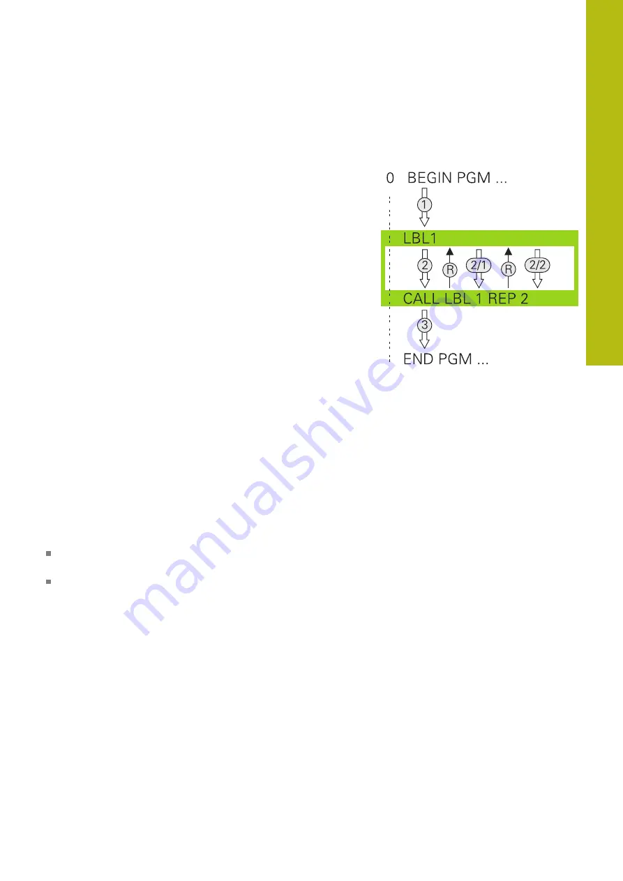
Program-section repeats
Label
The beginning of a program section repeat is marked by the label
LBL
. The end of a program section repeat is identified by
CALL LBL n REPn
.
Operating sequence
1 The control executes the part program up to the end of the
program section (
CALL LBL n REPn
)
2 Then the program section between the called LABEL and the
label call
CALL LBL n REPn
is repeated the number of times
entered after
REP
3 The control then continues with the part program
Programming notes
You can repeat a program section up to 65 534 times in
succession
The total number of times the program section is executed is
always one more than the programmed number of repeats,
because the first repeat starts after the first machining process.
Содержание TNC 640
Страница 4: ......
Страница 5: ...Fundamentals ...
Страница 36: ...Contents 36 HEIDENHAIN TNC 640 Conversational Programming User s Manual 10 2017 ...
Страница 67: ...1 First Steps with the TNC 640 ...
Страница 90: ......
Страница 91: ...2 Introduction ...
Страница 130: ......
Страница 131: ...3 Operating the Touchscreen ...
Страница 144: ......
Страница 145: ...4 Fundamentals File Management ...
Страница 206: ......
Страница 207: ...5 Programming Aids ...
Страница 236: ......
Страница 237: ...6 Tools ...
Страница 281: ...7 Programming Contours ...
Страница 333: ...8 Data Transfer from CAD Files ...
Страница 355: ...9 Subprograms and Program Section Repeats ...
Страница 374: ......
Страница 375: ...10 Programming Q Parameters ...
Страница 478: ......
Страница 479: ...11 Miscellaneous Functions ...
Страница 501: ...12 Special Functions ...
Страница 584: ......
Страница 585: ...13 Multiple Axis Machining ...
Страница 650: ......
Страница 651: ...14 Pallet Management ...
Страница 664: ......
Страница 665: ...15 Batch Process Manager ...
Страница 673: ...16 Turning ...
Страница 713: ...17 Manual Operation and Setup ...
Страница 797: ...18 Positioning with Manual Data Input ...
Страница 803: ...19 Test Run and Program Run ...
Страница 843: ...20 MOD Functions ...
Страница 881: ...21 Tables and Overviews ...