background image


Displaying operating times 16.7


16


TNC 320 | User's Manual

HEIDENHAIN Conversational Programming | 3/2014

505

16.6

Unit of Measurement

Application

This MOD function determines whether the coordinates are

displayed in millimeters (metric system) or inches.

To select the metric system (e.g. X = 15.789 mm), set the

Change MM/INCH function to mm. The value is displayed to 3

decimal places.
To select the inch system (e.g. X = 0.6216 inches), set the

Change MM/INCH function to inches. The value is displayed to

4 decimal places

If you would like to activate the inch display, the TNC shows the

feed rate in inch/min. In an inch program you must enter the feed

rate larger by a factor of 10.

16.7

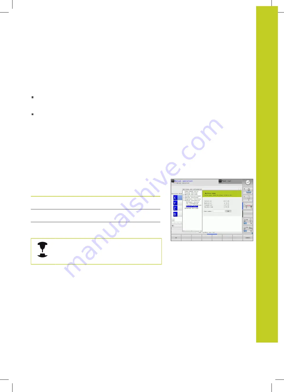
Displaying operating times

Application

The MACHINE TIME soft key enables you to see various types of

operating times:

Operating time

Meaning

Control on

Operating time of the control since

being put into service

Machine on

Operating time of the machine tool since

being put into service

Program run

Duration of controlled operation since

being put into service

The machine tool builder can provide further

operating time displays. Refer to your machine

manual.

Содержание TNC 320

Страница 1: ...TNC 320 User s Manual HEIDENHAIN Conversational Programming NC Software 771851 01 771855 01 English en 3 2014 ...

Страница 2: ...ositioning with manual data input Program run single block Program run full sequence Programming modes Key Function Programming Test run Program file management TNC functions Key Function Select or delete programs and files external data transfer Define program call select datum and point tables Select MOD functions Display help text for NC error messages call TNCguide Display all current error me...

Страница 3: ...tes Circular arc with center Circle with radius Circular arc with tangential connection Chamfer Corner rounding Special functions Key Function Show special functions Select the next tab in forms Up down one dialog box or button Entering and editing coordinate axes and numbers Key Function Select coordinate axes or enter them in a program Numbers Decimal point Reverse algebraic sign Polar coordinat...

Страница 4: ...Controls of the TNC 4 TNC 320 User s Manual HEIDENHAIN Conversational Programming 3 2014 ...

Страница 5: ...Fundamentals ...

Страница 6: ...to tool Danger to machine Danger to operator This symbol indicates a possibly dangerous situation that may cause light injuries if not avoided This symbol indicates that the described function must be adapted by the machine tool builder The function described may therefore vary depending on the machine This symbol indicates that you can find detailed information about a function in another manual ...

Страница 7: ...eters Some of the functions described in this manual may therefore not be among the features provided by the TNC on your machine tool TNC functions that may not be available on your machine include Tool measurement with the TT Please contact your machine tool builder to become familiar with the features of your machine Many machine manufacturers as well as HEIDENHAIN offer programming courses for ...

Страница 8: ...g Programming of cylindrical contours as if in two axes Feed rate in distance per minute Coordinate transformation Working plane tilting the Interpolation Circle in 3 axes with tilted working plane spacial arc HEIDENHAIN DNC option number 18 Communication with external PC applications over COM component DXF Converter software option option number 42 Supported DXF format AC1009 AutoCAD R12 For cont...

Страница 9: ...chine Upgrade functions are identified in the manual with FCL n where n indicates the sequential number of the feature content level You can purchase a code number in order to permanently enable the FCL functions For more information contact your machine tool builder or HEIDENHAIN Intended place of operation The TNC complies with the limits for a Class A device in accordance with the specification...

Страница 10: ...freely definable tables Freely definable tables page 373 New touch probe cycle 484 for calibrating the wireless TT 449 tool touch probe see User s Manual for Cycles The new HR 520 and HR 550 FS handwheels are supported Traverse with electronic handwheels page 412 New machining cycle 225 ENGRAVING see User s Manual for Cycle Programming New manual probing cycle Center line as datum Setting a center...

Страница 11: ...n in cycles see User s Manual for Cycle Programming A new optimization algorithm is now used with the KinematicsOpt cycles see User s Manual for Cycle Programming With Cycle 257 circular stud milling a parameter is now available with which you can determine the approach position on the stud see User s Manual for Cycle Programming With Cycle 256 rectangular stud a parameter is now available with wh...

Страница 12: ...ator you can calculate the spindle speed and the feed rate Cutting data calculator page 134 New if then decisions were introduced in the jump commands Programming if then decisions page 276 The character set of the fixed cycle 225 Engraving was expanded by more characters and the diameter sign see User s Manual for Cycle Programming New fixed cycle 275 trochoidal milling see User s Manual for Cycl...

Страница 13: ... be displayed in the input system Position Display Types page 504 Cycle 241 SINGLE LIP DEEP HOLE DRILLING was expanded by several input parameters see User s Manual for Cycle Programming Cycle 404 was expanded by the parameter Q305 NUMBER IN TABLE see User s Manual for Cycle Programming In the thread milling cycles 26x an approaching feed rate was introduced see User s Manual for Cycle Programming...

Страница 14: ...Fundamentals TNC model software and features 14 TNC 320 User s Manual HEIDENHAIN Conversational Programming 3 2014 ...

Страница 15: ...ing contours 181 7 Programming Data transfer from DXF files or plain language contours 233 8 Programming Subprograms and program section repeats 251 9 Programming Q Parameters 267 10 Programming Miscellaneous functions 337 11 Programming Special functions 357 12 Programming Multiple Axis Machining 379 13 Manual operation and setup 407 14 Positioning with Manual Data Input 463 15 Test run and progr...

Страница 16: ...Contents 16 TNC 320 User s Manual HEIDENHAIN Conversational Programming 3 2014 ...

Страница 17: ...e program 52 1 4 Graphically testing the first part 54 Selecting the correct operating mode 54 Selecting the tool table for the test run 54 Choosing the program you want to test 55 Selecting the screen layout and the view 55 Starting the test run 56 1 5 Setting up tools 57 Selecting the correct operating mode 57 Preparing and measuring tools 57 The tool table TOOL T 58 The pocket table TOOL_P TCH ...

Страница 18: ...yout 66 Control Panel 66 2 3 Modes of Operation 67 Manual Operation and El Handwheel 67 Positioning with Manual Data Input 67 Programming 67 Test Run 68 Program Run Full Sequence and Program Run Single Block 68 2 4 Status displays 69 General status display 69 Additional status displays 70 2 5 Window Manager 76 Task bar 77 2 6 SELinux security software 78 2 7 Accessories HEIDENHAIN 3 D Touch Probes...

Страница 19: ...lar coordinates 84 Absolute and incremental workpiece positions 85 Selecting the datum 86 3 2 Opening programs and entering 87 Organization of an NC program in HEIDENHAIN Conversational format 87 Define the blank BLK FORM 88 Opening a new part program 90 Programming tool movements in conversational 91 Actual position capture 93 Editing a program 94 The TNC search function 97 3 3 File manager Funda...

Страница 20: ...rectory 106 Creating a new file 106 Copying a single file 106 Copying files into another directory 107 Copying a table 108 Copying a directory 108 Choosing one of the last files selected 109 Deleting a file 110 Deleting a directory 110 Tagging files 111 Renaming a file 112 Sorting files 112 Additional functions 113 Additional tools for management of external file types 114 Data transfer to from an...

Страница 21: ...ucturing programs 130 Definition and applications 130 Displaying the program structure window Changing the active window 130 Inserting a structuring block in the left program window 130 Selecting blocks in the program structure window 130 4 5 Calculator 131 Operation 131 4 6 Cutting data calculator 134 Application 134 4 7 Programming graphics 136 Generate do not generate graphics during programmin...

Страница 22: ... Closing the error window 139 Detailed error messages 140 INTERNAL INFO soft key 140 Clearing errors 141 Error log 141 Keystroke log 142 Informational texts 143 Saving service files 143 Calling the TNCguide help system 144 4 9 TNCguide context sensitive help system 145 Application 145 Working with the TNCguide 146 Downloading current help files 150 ...

Страница 23: ...ompensation 156 Tool number tool name 156 Tool length L 156 Tool radius R 156 Delta values for lengths and radii 157 Entering tool data into the program 157 Enter tool data into the table 158 Importing tool tables 166 Pocket table for tool changer 167 Call tool data 170 Tool change 172 Tool usage test 174 5 3 Tool compensation 176 Introduction 176 Tool length compensation 176 Tool radius compensat...

Страница 24: ...th tangential connection APPR CT 192 Approaching on a circular path with tangential connection from a straight line to the contour APPR LCT 193 Departing in a straight line with tangential connection DEP LT 193 Departing in a straight line perpendicular to the last contour point DEP LN 194 Departing on a circular path with tangential connection DEP CT 195 Departing on a circular arc tangentially c...

Страница 25: ...nection 210 Helix 211 Example Linear movement with polar coordinates 213 Example Helix 214 6 6 Path contours FK free contour programming 215 Fundamentals 215 FK programming graphics 217 Initiating the FK dialog 219 Pole for FK programming 219 Free straight line programming 220 Free circular path programming 221 Input options 222 Auxiliary points 225 Relative data 226 Example FK programming 1 228 E...

Страница 26: ...r from DXF files or plain language contours 233 7 1 Processing DXF Files Software Option 234 Application 234 Opening a DXF file 235 Working with the DXF converter 235 Basic settings 236 Setting layers 238 Defining the datum 239 Selecting and saving a contour 241 Selecting and saving machining positions 245 ...

Страница 27: ...55 Operating sequence 255 Programming notes 255 Programming a program section repeat 255 Calling a program section repeat 256 8 4 Any desired program as subprogram 257 Operating sequence 257 Programming notes 257 Calling any program as a subprogram 258 8 5 Nesting 259 Types of nesting 259 Nesting depth 259 Subprogram within a subprogram 260 Repeating program section repeats 261 Repeating a subprog...

Страница 28: ...try 274 Definitions 274 Programming trigonometric functions 274 9 5 Calculation of circles 275 Application 275 9 6 If then decisions with Q parameters 276 Application 276 Unconditional jumps 276 Programming if then decisions 276 Abbreviations used 277 9 7 Checking and changing Q parameters 278 Procedure 278 9 8 Additional functions 280 Overview 280 FN 14 ERROR Displaying error messages 281 FN 16 F...

Страница 29: ...ring formulas directly 311 Entering formulas 311 Rules for formulas 313 Programming example 314 9 11 String parameters 315 String processing functions 315 Assigning string parameters 316 Chain linking string parameters 316 Converting a numerical value to a string parameter 317 Copying a substring from a string parameter 318 Converting a string parameter to a numerical value 319 Checking a string p...

Страница 30: ...7 Tool length Q114 327 Coordinates after probing during program run 328 Deviation between actual value and nominal value during automatic tool measurement with the TT 130 328 Tilting the working plane with mathematical angles rotary axis coordinates calculated by the TNC 328 Measurement results from touch probe cycles see also User s Manual for Cycle Programming 329 9 13 Programming examples 331 E...

Страница 31: ...130 342 10 4 Miscellaneous functions for path behavior 343 Machining small contour steps M97 343 Machining open contour corners M98 344 Feed rate factor for plunging movements M103 345 Feed rate in millimeters per spindle revolution M136 346 Feed rate for circular arcs M109 M110 M111 347 Calculating the radius compensated path in advance LOOK AHEAD M120 348 Superimposing handwheel positioning duri...

Страница 32: ...Axes U V and W 361 Overview 361 FUNCTION PARAXCOMP DISPLAY 362 FUNCTION PARAXCOMP MOVE 362 FUNCTION PARAXCOMP OFF 363 FUNCTION PARAXMODE 363 FUNCTION PARAXMODE OFF 364 11 3 File functions 365 Application 365 Defining file functions 365 11 4 Definition of a datum shift 366 Overview 366 TRANS DATUM AXIS 366 TRANS DATUM TABLE 367 TRANS DATUM RESET 368 11 5 Creating Text Files 369 Application 369 Open...

Страница 33: ...e tables 373 Fundamentals 373 Creating a freely definable table 373 Editing the table format 374 Switching between table and form view 375 FN 26 TAPOPEN Open a freely definable table 376 FN 27 TAPWRITE Write to a freely definable table 377 FN 28 TAPREAD Read from a freely definable table 378 ...

Страница 34: ...TED 387 Defining the working plane with the Euler angle PLANE EULER 388 Defining the working plane with two vectors PLANE VECTOR 390 Defining the working plane via three points PLANE POINTS 392 Defining the working plane via a single incremental spatial angle PLANE SPATIAL 394 Tilting the working plane through axis angle PLANE AXIAL FCL 3 function 395 Specifying the positioning behavior of the PLA...

Страница 35: ... limitation 423 13 4 Datum setting without a 3 D touch probe 424 Note 424 Preparation 424 Workpiece presetting with axis keys 424 Datum management with the preset table 425 13 5 Using 3 D touch probes 431 Overview 431 Functions in touch probe cycles 432 Selecting touch probe cycles 434 Recording measured values from the touch probe cycles 435 Writing measured values from the touch probe cycles in ...

Страница 36: ...iew 446 Datum setting in any axis 446 Corner as datum 447 Circle center as datum 449 Setting a center line as datum 451 Measuring workpieces with a 3 D touch probe 452 Using touch probe functions with mechanical probes or measuring dials 455 13 9 Tilting the working plane software option 1 456 Application function 456 Traversing reference points in tilted axes 458 Position display in a tilted syst...

Страница 37: ...AIN Conversational Programming 3 2014 37 14 Positioning with Manual Data Input 463 14 1 Programming and executing simple machining operations 464 Positioning with manual data input MDI 464 Protecting and erasing programs in MDI 467 ...

Страница 38: ...nk in the working space 479 Application 479 15 3 Functions for program display 480 Overview 480 15 4 Test Run 481 Application 481 15 5 Program run 483 Application 483 Running a part program 484 Interrupt machining 485 Moving the machine axes during an interruption 486 Resuming program run after an interruption 486 Retraction after a power interruption 488 Any entry into program mid program startup...

Страница 39: ...TNC 320 User s Manual HEIDENHAIN Conversational Programming 3 2014 39 15 8 Optional program run interruption 496 Application 496 ...

Страница 40: ...OD functions 499 16 2 Graphic settings 500 16 3 Machine settings 501 External access 501 Tool usage file 501 Select kinematics 502 16 4 System settings 503 Set the system time 503 16 5 Position Display Types 504 Application 504 16 6 Unit of Measurement 505 Application 505 16 7 Displaying operating times 505 Application 505 16 8 Software numbers 506 Application 506 16 9 Entering the code number 506...

Страница 41: ...e system for file operations fileSystem 509 Settings for data transfer with the TNCserver PC software 509 Setting the operating mode of the external device fileSystem 510 Data transfer software 511 16 11Ethernet interface 513 Introduction 513 Connection options 513 Configuring the TNC 513 16 12Firewall 519 Application 519 16 13Configure HR 550 FS wireless handwheel 522 Application 522 Assigning th...

Страница 42: ...sories 550 Comparison PC software 550 Comparison Machine specific functions 551 Comparison User functions 551 Comparator Cycles 558 Comparison Miscellaneous functions 561 Comparison Touch probe cycles in the Manual Operation and El Handwheel modes 563 Comparison Touch probe cycles for automatic workpiece inspection 563 Comparison Differences in programming 565 Comparison Differences in Test Run fu...

Страница 43: ...1 First Steps with the TNC 320 ...

Страница 44: ... can vary depending on the machine tool Refer to your machine manual Switch on the power supply for TNC and machine The TNC starts the operating system This process may take several minutes Then the TNC will display the Power interrupted message in the screen header Press the CE key The TNC compiles the PLC program Switch on the machine control voltage The TNC checks operation of the emergency sto...

Страница 45: ... information on this topic Operating modes see Programming page 67 The most important TNC keys Functions for conversational guidance Key Confirm entry and activate the next dialog prompt Ignore the dialog question NO ENT End the dialog immediately Abort dialog discard entries Soft keys on the screen with which you select functions appropriate to the active state Further information on this topic W...

Страница 46: ... on the TNC hard disk Use the arrow keys to select the folder in which you want to open the new file Enter any desired file name with the extension H The TNC then automatically opens a program and asks for the unit of measure for the new program Selecting the unit of measure Press the MM or INCH soft key The TNC automatically generates the first and last blocks of the program Afterwards you can no...

Страница 47: ... key Workpiece blank def minimum Y Smallest Y coordinate of the workpiece blank with respect to the reference point e g 0 Confirm with the ENT key Workpiece blank def minimum Z Smallest Z coordinate of the workpiece blank with respect to the reference point e g 40 Confirm with the ENT key Workpiece blank def maximum X Largest X coordinate of the workpiece blank with respect to the reference point ...

Страница 48: ...ol end program Further information on this topic Contour programming see Tool movements in the program Layout of contour machining programs 0 BEGIN PGM BSPCONT MM 1 BLK FORM 0 1 Z X Y Z 2 BLK FORM 0 2 X Y Z 3 TOOL CALL 5 Z S5000 4 L Z 250 R0 FMAX 5 L X Y R0 FMAX 6 L Z 10 R0 F3000 M13 7 APPR RL F500 16 DEP X Y F3000 M9 17 L Z 250 R0 FMAX M2 18 END PGM BSPCONT MM Recommended program layout for simpl...

Страница 49: ...itioning block Pre position the tool in the working plane Press the orange axis key X and enter the value for the position to be approached e g 20 Press the orange axis key Y and enter the value for the position to be approached e g 20 Confirm your entry with the ENT key Radius comp RL RR no comp confirm with the ENT key Activate no radius compensation Confirm Feed rate F with the ENT key Move at ...

Страница 50: ...er only the Y coordinate 95 and save your entry with the END key Approach contour point 3 Enter the X coordinate 95 and save your entry with the END key Define the chamfer at the contour point 3 Enter the chamfer width 10 mm and confirm with the END key Approach contour point 4 Enter the Y coordinate 5 and save your entry with the END key Define the chamfer at the contour point 4 Enter the chamfer...

Страница 51: ... end of program then confirm with the END key The TNC saves the entered positioning block Further information on this topic Complete example with NC blocks see Example Linear movements and chamfers with Cartesian coordinates page 205 Creating a new program see Opening programs and entering page 87 Approaching departing contours see Approaching and departing a contour page 188 Programming contours ...

Страница 52: ...tion F with the END key The TNC stores the entered positioning block Call the cycle menu Display the drilling cycles Select standard drilling cycle 200 The TNC starts the dialog for cycle definition Enter all parameters requested by the TNC step by step and conclude each entry with the ENT key In the screen to the right the TNC also displays a graphic showing the respective cycle parameter Call th...

Страница 53: ... 0 Y 0 Z 40 Definition of workpiece blank 2 BLK FORM 0 2 X 100 Y 100 Z 0 3 TOOL CALL 5 Z S4500 Tool call 4 L Z 250 R0 FMAX Retract the tool 5 PATTERN DEF POS1 X 10 Y 10 Z 0 POS2 X 10 Y 90 Z 0 POS3 X 90 Y 90 Z 0 POS4 X 90 Y 10 Z 0 Define the machining positions 6 CYCL DEF 200 DRILLING Define the cycle Q200 2 SET UP CLEARANCE Q201 20 DEPTH Q206 250 FEED RATE FOR PLNGNG Q202 5 INFEED DEPTH Q210 0 DWE...

Страница 54: ...ve not activated a tool table in the Test Run mode Press the PGM MGT key The TNC opens the file management Press the select type soft key The TNC shows a soft key menu for selection of the file type to be displayed Press the DEFAULT soft key The TNC shows all saved files in the right window Move the highlight to the left onto the directories Move the highlight to the TNC directory Move the highlig...

Страница 55: ...ing with the file manager page 102 Selecting the screen layout and the view Press the key for selecting the screen layout The TNC displays all available alternatives in the soft key row Press the PROGRAM GRAPHICS soft key In the left half of the screen the TNC shows the program in the right half it shows the workpiece blank Press the FURTHER VIEW OPTIONS soft key Move the soft key row further and ...

Страница 56: ...o a programmed break or to the program end While the simulation is running you can use the soft keys to change views Press the STOP soft key The TNC interrupts the test run Press the START soft key the TNC resumes the test run after an interruption Further information on this topic Running a test run see Test Run page 481 Graphic functions see Graphics page 470 Adjust the simulation speed see Spee...

Страница 57: ...tches to the Manual mode of operation Further information on this topic Operating modes of the TNC see Modes of Operation page 67 Preparing and measuring tools Clamp the required tools in their chucks When measuring with an external tool presetter Measure the tools note down the length and radius or transfer them directly to the machine through a transfer program When measuring on the machine stor...

Страница 58: ...ions To enter tool data in the tool table TOOL T proceed as follows Display the tool table Edit the tool table Set the EDITING soft key to ON With the upward or downward arrow keys you can select the tool number that you want to edit With the rightward or leftward arrow keys you can select the tool data that you want to edit To exit the tool table press the END key Further information on this topi...

Страница 59: ...H proceed as follows Displaying the tool table The TNC shows the tool table Display the pocket table The TNC shows the pocket table Edit the pocket table Set the EDIT soft key to ON With the upward or downward arrow keys you can select the pocket number that you want to edit With the rightward or leftward arrow keys you can select the data that you want to edit Exit the pocket table press the END ...

Страница 60: ... key The TNC switches to the Manual mode of operation Further information on this topic Manual Operation mode see Moving the machine axes page 411 Clamping the workpiece Mount the workpiece with a fixture on the machine table If you have a 3 D touch probe on your machine then you do not need to clamp the workpiece parallel to the axes If you do not have a 3 D touch probe available you have to alig...

Страница 61: ...edge Press NC start Press NC start The touch probe moves in the defined direction until it contacts the workpiece and then automatically returns to its starting point Use the axis direction keys to pre position the touch probe to a position near the first touch point on the second workpiece edge Select the probing direction via soft key Press NC start Press NC start The touch probe moves in the de...

Страница 62: ...that mode and runs the program after NC start up to a program interruption or to the end of the program Further information on this topic Operating modes of the TNC see Modes of Operation page 67 Running programs see Program run page 483 Choosing the program you want to run Press the PGM MGT key The TNC opens the file management Press the LAST FILES soft key The TNC opens a pop up window with the ...

Страница 63: ...2 Introduction ...

Страница 64: ...an especially easy method of writing programs Interactive graphics illustrate the individual machining steps for programming the contour If a production drawing is not dimensioned for NC the FK free contour programming feature performs the necessary calculations automatically Workpiece machining can be graphically simulated either during or before actual machining It is also possible to program th...

Страница 65: ...ox where the dialog prompts and TNC messages also appear unless the TNC is showing only graphics 2 Soft keys In the footer the TNC indicates additional functions in a soft key row You can select these functions by pressing the keys immediately below them The lines immediately above the soft key row indicate the number of soft key rows that can be called with the black arrow keys to the right and l...

Страница 66: ...tions see Operating modes page 62 Select the desired screen layout Control Panel The TNC 320 is delivered with an integrated keyboard As an alternative the TNC 320 is also available with a separate display unit and an operating panel with alphabetic keyboard 1 Alphabetic keyboard for entering texts and file names and for ISO programming 2 File management Calculator MOD function HELP function 3 Pro...

Страница 67: ... key Positions Left positions right status display Positioning with Manual Data Input This mode of operation is used for programming simple traversing movements such as for face milling or prepositioning Soft keys for selecting the screen layout Window Soft key Program Left program blocks right status display Programming In this mode of operation you can write your part programs The FK free progra...

Страница 68: ... the screen layout see Program Run Full Sequence and Program Run Single Block page 68 Program Run Full Sequence and Program Run Single Block In the Program Run Full Sequence mode of operation the TNC executes a part program continuously to its end or to a manual or programmed stop You can resume program run after an interruption In the Program Run Single Block mode of operation you execute each bl...

Страница 69: ...e window Information in the status display Icon Meaning ACTL Position display Actual nominal or distance to go coordinates mode Machine axes the TNC displays auxiliary axes in lower case letters The sequence and quantity of displayed axes is determined by the machine tool builder Refer to your machine manual for more information Number of the active presets from the preset table If the datum was s...

Страница 70: ...reen layout Select the layout option for the additional status display In the right half of the screen the TNC shows the OVERVIEW status form To select an additional status display Switch the soft key rows until the STATUS soft keys appear Either select the additional status display directly by soft key e g positions and coordinates or use the switch over soft keys to select the desired view The a...

Страница 71: ...ous detail forms Soft key Meaning Position display Tool information Active M functions Active coordinate transformations Active subprogram Active program section repeat Program called with PGM CALL Current machining time Name of the active main program General program information PGM tab Soft key Meaning No direct selection possible Name of the active main program Circle center CC pole Dwell time ...

Страница 72: ... possible Active program section repeats with block number label number and number of programmed repeats repeats yet to be run Active subprogram numbers with block number in which the subprogram was called and the label number that was called Information on standard cycles CYC tab Soft key Meaning No direct selection possible Active machining cycle Active values of Cycle 32 Tolerance ...

Страница 73: ...ey Meaning No direct selection possible List of the active M functions with fixed meaning List of the active M functions that are adapted by your machine manufacturer Positions and coordinates POS tab Soft key Meaning Type of position display e g actual position Tilt angle of the working plane Angle of a basic rotation Active kinematics ...

Страница 74: ...or TOOL CALL TIME 2 Display of programmed tool and replacement tool Tool measurement TT tab The TNC displays the TT tab only if the function is active on your machine Soft key Meaning No direct selection possible Number of the tool to be measured Display whether the tool radius or the tool length is being measured MIN and MAX values of the individual cutting edges and the result of measuring the r...

Страница 75: ...NC displays an active datum shift in up to 8 axes Mirrored axes Cycle 8 Active basic rotation Active rotation angle Cycle 10 Active scaling factor factors Cycles 11 26 The TNC displays an active scaling factor in up to 6 axes Scaling datum For further information refer to the User s Manual for Cycles Coordinate Transformation Cycles Displaying Q parameters QPARA tab Soft key Meaning Display the cu...

Страница 76: ...dow manager Display a task bar for switching between various applications user interfaces Manage an additional desktop on which special applications from your machine tool builder can run Control the focus between NC software applications and those of the machine tool builder The size and position of pop up windows can be changed It is also possible to close minimize and restore the pop up windows...

Страница 77: ...e TNC NC Control Start and stop the TNC software Only permitted for diagnostic purposes Web Browser Start Mozilla Firefox Diagnostics Available only to authorized specialists to start diagnostic functions Settings Configuration of miscellaneous settings Date Time Set the date and time Language Language setting for the system dialogs During startup the TNC overwrites this setting with the language ...

Страница 78: ... prepared to permit running of only those programs installed with the HEIDENHAIN NC software Other programs cannot be run with the standard installation The access control of SELinux under HEROS 5 is regulated as follows The TNC runs only those applications installed with the HEIDENHAIN NC software Files in connection with the safety of the software SELinux system files HEROS 5 boot files etc may ...

Страница 79: ...e and is a cost effective alternative for applications where digitizing is not frequently required The TS 640 see figure and the smaller TS 440 feature infrared transmission of the triggering signal to the TNC This makes them highly convenient for use on machines with automatic tool changers Principle of operation HEIDENHAIN triggering touch probes feature a wear resisting optical switch that gene...

Страница 80: ...DENHAIN Conversational Programming 3 2014 HR electronic handwheels Electronic handwheels facilitate moving the axis slides precisely by hand A wide range of traverses per handwheel revolution is available Apart from the HR 130 and HR 150 panel mounted handwheels HEIDENHAIN also offers the HR 410 portable handwheel ...

Страница 81: ...3 Programming Fundamentals file management ...

Страница 82: ...For linear encoders with distance coded reference marks the machine axes need to move by no more than 20 mm for angle encoders by no more than 20 With absolute encoders an absolute position value is transmitted to the control immediately upon switch on In this way the assignment of the actual position to the machine slide position is re established directly after switch on Reference system A refer...

Страница 83: ...Z axis the thumb points in the positive X direction and the index finger in the positive Y direction The TNC 320 can control up to 5 axes The axes U V and W are secondary linear axes parallel to the main axes X Y and Z respectively Rotary axes are designated as A B and C The illustration at lower right shows the assignment of secondary axes and rotary axes to the main axes Designation of the axes ...

Страница 84: ...space polar coordinates are two dimensional and describe points in a plane Polar coordinates have their datum at a circle center CC or pole A position in a plane can be clearly defined by the Polar Radius the distance from the circle center CC to the position and the Polar Angle the value of the angle between the angle reference axis and the line that connects the circle center CC with the positio...

Страница 85: ... position of the tool which serves as the relative imaginary datum When you write an NC program in incremental coordinates you thus program the tool to move by the distance between the previous and the subsequent nominal positions This is why they are also referred to as chain dimensions To program a position in incremental coordinates enter the function I before the axis Example 2 Holes dimension...

Страница 86: ...ply use the coordinate transformation cycles see User s Manual for Cycles Cycles for Coordinate Transformation If the production drawing is not dimensioned for NC set the datum at a position or corner on the workpiece from which the dimensions of the remaining workpiece positions can be most easily measured The fastest easiest and most accurate way of setting the datum is by using a 3 D touch prob...

Страница 87: ...ck of a program is identified by BEGIN PGM the program name and the active unit of measure The subsequent blocks contain information on The workpiece blank Tool calls Approaching a safe position Feed rates and spindle speeds as well as Path contours cycles and other functions The last block of a program is identified by END PGM the program name and the active unit of measure After each tool call H...

Страница 88: ...The TNC can depict various types of blank forms Soft key Function Define a workpiece blank Define a cylindrical blank Define a rotationally symmetric blank Rectangular blank The sides of the cuboid lie parallel to the X Y and Z axes This blank is defined by two of its corner points MIN point the smallest X Y and Z coordinates of the blank form entered as absolute values MAX point the largest X Y a...

Страница 89: ...t of measure Rotationally symmetric blank of any shape You define the contour of the rotationally symmetric blank in a subprogram In the workpiece blank definition you refer to the contour description DIM_D DIM_R Diameter or radius of the rotationally symmetrical blank form LBL Subprogram with the contour description The subprogram can be designated with a number an alphanumeric name or a QS param...

Страница 90: ...Select a rectangular workpiece blank Press the soft key for a rectangular blank form WORKING PLANE IN GRAPHIC XY Z Enter spindle axis e g Z WORKPIECE BLANK DEF MINIMUM Enter in sequence the X Y and Z coordinates of the MIN point and confirm each of your entries with the ENT key WORKPIECE BLANK DEF MAXIMUM Enter in sequence the X Y and Z coordinates of the MAX point and confirm each of your entries...

Страница 91: ...ng block Open block COORDINATES 10 Enter the target coordinate for the X axis Y 20 Enter the target coordinate for the Y axis go to the next question with ENT RADIUS COMP RL RR NO COMP Enter No radius compensation and go to the next question with ENT FEED RATE F F MAX ENT 100 Enter a feed rate of 100 mm min for this path contour go to the next question with ENT MISCELLANEOUS FUNCTION M Enter 3 mis...

Страница 92: ...automatically calculated in TOOL CALL Move at the programmed feed rate unit of measure is mm min or 1 10 inch min With rotary axes the TNC interprets the feed rate in degrees min regardless of whether the program is written in mm or inches Define the feed per revolution units in mm rev or inch rev Caution In inch programs FU cannot be combined with M136 Define the tooth feed units in mm tooth or i...

Страница 93: ... the active input box In the working plane the TNC always captures the coordinates of the tool center even though tool radius compensation is active In the tool axis the TNC always captures the coordinates of the tool tip and thus always takes the active tool length compensation into account The TNC keeps the soft key row for axis selection active until you deactivate it by pressing the actual pos...

Страница 94: ... next page Go to beginning of program Go to end of program Change the position of the current block on the screen Press this soft key to display additional program blocks that are programmed before the current block Change the position of the current block on the screen Press this soft key to display additional program blocks that are programmed after the current block Move from one block to the n...

Страница 95: ...overwrite it with the new one The plain language dialog is available while the word is highlighted To accept the change press the END key If you want to insert a word press the horizontal arrow key repeatedly until the desired dialog appears You can then enter the desired value Looking for the same words in different blocks Set the AUTO DRAW soft key to OFF To select a word in a block press the ar...

Страница 96: ...k press the SELECT BLOCK soft key The TNC then highlights the first character of the block and the CANCEL SELECTION soft key appears Move the highlight to the last first block of the program section you wish to copy or delete The TNC shows the marked blocks in a different color You can end the marking function at any time by pressing the CANCEL SELECTION soft key To copy the selected program secti...

Страница 97: ... a program and replace it by a new text if required Finding any text If required select the block containing the word you wish to find Select the search function The TNC superimposes the search window and displays the available search functions in the soft key row see table of search functions 40 Enter the text to be searched for The search is case sensitive Start the search process The TNC moves ...

Страница 98: ... wish to find Select the Search function The TNC superimposes the search window and displays the available search functions in the soft key row Enter the text to be searched for Please note that the search is case sensitive Then confirm with the ENT key Enter the text to be inserted Please note that the entry is case sensitive Start the search process The TNC moves to the next occurrence of the te...

Страница 99: ... Help files A TXT CHM Drawing data as ASCII files DXF When you write a part program on the TNC you must first enter a program name The TNC saves the program to the hard disk as a file with the same name The TNC can also save texts and tables as files The TNC provides a special file management window in which you can easily find and manage your files Here you can call copy rename and erase files Wi...

Страница 100: ...cters otherwise the TNC cannot display the entire file name File names on the TNC must comply with this standard The Open Group Base Specifications Issue 6 IEEE Std 1003 1 2004 Edition Posix Standard Accordingly the file names may include the characters below A B C D E F G H I J K L M N O P Q R S T U V W X Y Z a b c d e f g h i j k l m n o p q r s t u v w x y z 0 1 2 3 4 5 6 7 8 9 _ You should not...

Страница 101: ...nformation about displaying and editing the listed file types see page 114 Data Backup We recommend saving newly written programs and files on a PC at regular intervals The TNCremoNT data transmission freeware from HEIDENHAIN is a simple and convenient method for backing up data stored on the TNC You additionally need a data medium on which all machine specific data such as the PLC program machine...

Страница 102: ...path indicates the drive and all directories and subdirectories under which a file is saved The individual names are separated by a backslash The path including all drive characters directory and the file name including the extension must not exceed 82 characters Drive designations must not include more than 8 uppercase letters Example The directory AUFTR1 was created on the TNC drive Then in the ...

Страница 103: ...Display the last 10 files that were selected 109 Delete a file or directory 110 Tag a file 111 Rename a file 112 Protect a file against editing and erasure 113 Cancel file protection 113 Importing tool tables 166 Manage network drives 121 Select the editor 113 Sort files by properties 112 Copy a directory 108 Delete directory with all its subdirectories Display all the directories of a particular ...

Страница 104: ...left and the directory name to the right Subdirectories are shown to the right of and below their parent directories A triangle in front of the folder symbol indicates that there are further subdirectories which can be shown with the or ENT keys The wide window on the right shows you all files that are stored in the selected directory Each file is shown with additional information illustrated in t...

Страница 105: ...ve Move the highlight to the desired drive in the left window Select a drive Press the SELECT soft key or Press the ENT key Step 2 Select a directory Move the highlight to the desired directory in the left hand window the right hand window automatically shows all files stored in the highlighted directory Step 3 Select a file Press the SELECT TYPE soft key Press the soft key for the desired file ty...

Страница 106: ...e NEW Enter the new file name with the file extension and confirm with ENT Copying a single file Move the highlight to the file you wish to copy Press the COPY soft key Select the copying function The TNC opens a pop up window Enter the name of the destination file and confirm your entry with the ENT key or the OK soft key The TNC copies the file into the active directory or into the selected targ...

Страница 107: ...the highlight to the file you want to copy and tag it You can tag several files in this way if desired Copy the tagged files into the target directory Additional tagging functions see Tagging files page 111 If you have tagged files in both the left and right windows the TNC copies from the directory in which the highlight is located Overwriting files If you copy files into a directory in which oth...

Страница 108: ...le management The TNC asks if you wish to overwrite the existing TOOL T tool table If you press the YES soft key the TNC will completely overwrite the current TOOL T tool table After the copying process the new TOOL T table consists of 10 lines Or press the REPLACE FIELDS soft key for the TNC to overwrite the 10 lines in the TOOL T file The data of the other lines is not changed Extracting lines f...

Страница 109: ...Choosing one of the last files selected Call the file manager To display the 10 files last selected Press the LAST FILES soft key Use the arrow keys to move the highlight to the file you wish to select Moves the highlight up and down within a window To select a file Press the OK soft key or Press the ENT key ...

Страница 110: ... TNC asks whether you really want to delete the file To confirm deletion press the OK soft key or To interrupt deletion Press the CANCEL soft key Deleting a directory Caution Data may be lost Once you delete files they cannot be restored Move the highlight to the directory you want to delete To select the erasing function Press the DELETE soft key The TNC inquires whether you really intend to dele...

Страница 111: ...vidual files but also for several files at once To tag several files proceed as follows Move the highlight to the first file To display the tagging functions Press the TAG soft key To tag a file Press the TAG FILE soft key Move the highlight to the next file you wish to tag Only works via soft keys Do not use the arrow keys To tag another file Press the TAG FILE soft key etc To copy tagged files P...

Страница 112: ...enaming a file Move the highlight to the file you wish to rename Select the renaming function Enter the new file name the file type cannot be changed To rename Press the OK soft key or the ENT key Sorting files Select the folder in which you wish to sort the files Select the SORT soft key Select the soft key with the corresponding display criterion ...

Страница 113: ...ting the editor Move the highlight in the right window onto the file you want to open To select additional functions Press the MORE FUNCTIONS soft key To select the editor with which to open the selected file press the SELECT EDITOR soft key Mark the desired editor Press the OK soft key to open the file Connecting removing a USB device Move the highlight to the left window To select additional fun...

Страница 114: ...inary transmission menu item Extras Configuration Mode in TNCremoNT Displaying PDF files To open PDF files directly on the TNC proceed as follows Call the file manager Select the directory in which the PDF file is saved Move the highlight to the PDF file Press ENT The TNC opens the PDF file in its own application using the PDF viewer additional tool With the key combination ALT TAB you can always ...

Страница 115: ...d under Help To exit Gnumeric proceed as follows Use the mouse to select the File menu item Select the menu item Quit The TNC returns to the file manager Displaying Internet files To open Internet files with the extension htm or html directly on the TNC proceed as follows Call the file manager Select the directory in which the Internet file is saved Move the highlight to the Internet file Press EN...

Страница 116: ...ce while leaving the archive file open Alternatively you can also click the corresponding symbol in the taskbar to switch back to the TNC interface If you position the mouse pointer over a button a brief tooltip explaining the function of this button will be displayed More information on how to use the Xarchiver function is provided under Help Please note that the TNC does not carry out any binary...

Страница 117: ...own application using the Mousepad additional tool If you open an H or I file on an external drive and save it on the TNC drive using Mousepad the programs are not converted automatically to the internal control format Programs that are saved in this way cannot be run or opened with the TNC editor With the key combination ALT TAB you can always return to the TNC user interface while leaving the te...

Страница 118: ... to the graphics file Press the ENT key The TNC opens the text file in its own application using the Mousepad additional tool With the key combination ALT TAB you can always return to the TNC user interface while leaving the graphics file open Alternatively you can also click the corresponding symbol in the taskbar to switch back to the TNC interface More information on how to use the ristretto fu...

Страница 119: ...r occasionally when you transmit data over a serial interface They can be overcome by repeating the transmission Call the file manager Select the screen layout for the data transfer Press the WINDOW key In the left half of the screen the TNC shows all files in the current directory In the right half of the screen it shows all files saved in the root directory TNC Use the arrow keys to highlight th...

Страница 120: ...window Select the desired directory in the pop up window by using the arrow keys and the ENT key Transmitting individual files Press the COPY soft key or To transfer several files To transfer several files press the TAG soft key in the second soft key row see Tagging files page 111 Confirm with the OK or with the ENT key A status window appears on the TNC informing about the copying progress or To...

Страница 121: ...sary press the WINDOW key to set up the screen as it is shown at upper right To select the network settings Press the NETWORK soft key second soft key row To manage the network drives Press the DEFINE NETWORK CONNECTN soft key In a window the TNC shows the network drives available for access With the soft keys described below you can define the connection for each drive Function Soft key Establish...

Страница 122: ... USB devices with other file systems such as NTFS The TNC displays the USB TNC does not support device error message when such a device is connected The TNC also displays the USB TNC does not support device error message if you connect a USB hub In this case simply acknowledge the message with the CE key In theory you should be able to connect all USB devices with the file systems mentioned above ...

Страница 123: ...with the arrow key Use the arrow keys to select the USB device to be removed Scroll through the soft key row Select additional functions Select the function for removing USB devices The TNC removes the USB device from the directory tree Exit the file manager In order to re establish a connection with a USB device that has been removed press the following soft key Select the function for reconnecti...

Страница 124: ......

Страница 125: ...4 Programming Programming aids ...

Страница 126: ...y name using the screen keyboard The TNC opens a window in which the numeric entry field of the TNC is displayed with the corresponding letters assigned You can move the cursor to the desired character by repeatedly pressing the respective key Wait until the selected character is transferred to the input field before you enter the next character Use the OK soft key to load the text into the open d...

Страница 127: ...general notes If the TNC cannot show the entire comment on the screen the sign is displayed The last character in a comment block must not have any tilde Entering a comment in a separate block Select the block after which the comment is to be inserted Initiate the programming dialog with the semicolon key on the alphabetic keyboard Enter your comment and conclude the block by pressing the END key ...

Страница 128: ...al Programming 3 2014 Functions for editing of the comment Function Soft key Jump to beginning of comment Jump to end of comment Jump to the beginning of a word Words must be separated by a space Jump to the end of a word Words must be separated by a space Switch between insert mode and overwrite mode ...

Страница 129: ...ng Programs are made more legible and clear with color highlighting Color highlighting of syntax elements Use Color Standard color Black Display of comments Green Display of numerical values Blue Block number Purple Scrollbar You can move the screen content with the mouse via the scrollbar on the right edge of the program window In addition the size and position of the scrollbar indicates program ...

Страница 130: ...added to as desired The inserted structure items are managed by the TNC in a separate file extension SEC DEP This speeds navigation in the program structure window Displaying the program structure window Changing the active window To display the program structure window select the screen display PGM SECTS To change the active window press the soft key Inserting a structuring block in the left prog...

Страница 131: ...nds via soft key or through the alphabetic keyboard Mathematical function Command key Addition Subtraction Multiplication Division Calculations in parentheses Arc cosine ARC Sine SIN Cosine COS Tangent TAN Powers of values X Y Square root SQRT Inversion 1 x pi 3 14159265359 PI Add value to buffer memory M Save the value to buffer memory MS Recall from buffer memory MR Delete buffer memory contents...

Страница 132: ...e the arrow keys to select the word into which the calculated value is to be transferred Superimpose the on line calculator by pressing the CALC key and perform the desired calculation Press the actual position capture key or the APPLY VALUE soft key for the TNC to transfer the calculated value into the active input box and to close the calculator You can also transfer values from a program into t...

Страница 133: ...l value from the active input field into the pocket calculator Load the numerical value from the pocket calculator field into the active input field Copy the numerical value from the pocket calculator Insert the copied numerical value into the pocket calculator Open the cutting data calculator Position the calculator in the center You can also shift the calculator with the arrow keys on your keybo...

Страница 134: ... per minute To open the cutting data calculator press the CUTTING DATA CALCULATOR soft key The TNC shows the soft key if you open the pocket calculator CALC key open the dialog field for spindle speed input in the TOOL CALL block open the dialog field for feed rate input in positioning blocks or cycles enter a feed rate in manual operation F soft key enter a spindle speed in manual operation S sof...

Страница 135: ...ing data calculator form into an open dialog field Load the feed per tooth from the cutting data calculator form into an open dialog field Load the feed per revolution from the cutting data calculator form into an open dialog field Load the tool radius into the cutting data calculator form Load the spindle speed from the opened dialog form into the cutting data calculator form Load the feed rate f...

Страница 136: ... path contour you program in the graphics window in the right screen half If you do not wish to have the TNC generate graphics during programming set the AUTO DRAW soft key to OFF Even when AUTO DRAW ON is active graphics are not generated for program section repeats Generating a graphic for an existing program Use the arrow keys to select the block up to which you want the graphic to be generated...

Страница 137: ... picture To show block numbers Set the SHOW OMIT BLOCK NO soft key to SHOW To omit block numbers Set the SHOW OMIT BLOCK NO soft key to OMIT Erasing the graphic Shift the soft key row See picture To erase the graphic Press the CLEAR GRAPHIC soft key Showing grid lines Shift the soft key row See picture Show grid lines Press the Show grid lines soft key ...

Страница 138: ...w see figure The following functions are available Function Soft key Show and move the frame overlay Press and hold the desired soft key to move the frame overlay Shrink the frame overlay Press soft key for shrinking Enlarge the frame overlay Press soft key Confirm the selected area with the WINDOW DETAIL soft key The RESET WORKPIECE BLANK soft key is used to restore the original section If you ha...

Страница 139: ...rror is displayed in red type Complete information on all pending errors is shown in the error window If a rare processor check error should occur the TNC automatically opens the error window You cannot remove such an error Shut down the system and restart the TNC The error message is displayed in the header until it is cleared or replaced by a higher priority error An error message that contains ...

Страница 140: ... INFO soft key The TNC opens a window with information on the error cause and corrective action Exit Info Press the MORE INFO soft key again INTERNAL INFO soft key The INTERNAL INFO soft key supplies information on the error message This information is only required if servicing is needed Open the error window Detailed information about the error message Position the highlight on the error message...

Страница 141: ...the error has not been removed the error message cannot be deleted In this case the error message remains in the window Error log The TNC stores errors and important events e g system startup in an error log The capacity of the error log is limited If the log is full the TNC uses a second file If this is also full the first error log is deleted and written to again and so on To view the error hist...

Страница 142: ... second file becomes full the first keystroke log is cleared and written to again and so on To view the keystroke history switch between CURRENT FILE and PREVIOUS FILE Press the LOG FILES soft key Open the keystroke log file Press the KEYSTROKE LOG FILE soft key If you need the previous log file Press the PREVIOUS FILE soft key If you need the current log file Press the Current File soft key The T...

Страница 143: ...upon the next valid input Saving service files If necessary you can save the Current status of the TNC and make it available to a service technician for evaluation A group of service files is saved error and keystroke log files as well as other files that contain information about the current status of the machine and the machining If you repeat the Save service files function with the same file n...

Страница 144: ...hows you the same error explanation that you receive by pressing the HELP soft key If your machine manufacturer also provides a help system the TNC shows an additional MACHINE MANUFACTURER soft key with which you can call this separate help system There you will find further more detailed information on the error message concerned Call the help for HEIDENHAIN error messages Call the help for HEIDE...

Страница 145: ... you are usually brought to the exact place in the documentation that describes the corresponding function The TNC always tries to start the TNCguide in the language that you have selected as the conversational language on your TNC If the files with this language are not yet available on your TNC it automatically opens the English version The following user documentation is available in the TNCgui...

Страница 146: ...therwise a browser adapted by HEIDENHAIN For many soft keys there is a context sensitive call through which you can go directly to the description of the soft key s function This functionality requires using a mouse Proceed as follows Select the soft key row containing the desired soft key Click with the mouse on the help symbol that the TNC displays just above the soft key row The mouse pointer t...

Страница 147: ...or upward if texts or graphics are not shown completely If the table of contents at left is active Open up the table of contents If the branch is at its end jump into the window at right If the text window at right is active No function If the table of contents at left is active Close the table of contents If the text window at right is active No function If the table of contents at left is active...

Страница 148: ...is active the TNC reduces the window size automatically before the change of focus Exiting TNCguide Subject index The most important subjects in the Manual are listed in the subject index Index tab You can select them directly by mouse or with the cursor keys The left side is active Select the Index tab Activate the Keyword input field Enter the word for the desired subject and the TNC synchronize...

Страница 149: ... Enter the desired word and confirm with the ENT key The TNC lists all sources containing the word Use the arrow key to highlight the desired source Press the ENT key to go to the selected source You can enter the search word only with a keyboard connected via USB The full text search only works for single words If you activate the Search only in titles function by mouse or by using the cursor and...

Страница 150: ...elect the desired language TNC Controls Series e g TNC 300 Desired NC software number e g TNC 320 77185x 01 Select the desired language version from the TNCguide online help table Download the ZIP file and unpack it Move the unzipped CHM files to the TNC in the TNC tncguide en directory or into the respective language subdirectory see also the following table If you want to use TNCremoNT to transf...

Страница 151: ...t Spanish TNC tncguide es Portuguese TNC tncguide pt Swedish TNC tncguide sv Danish TNC tncguide da Finnish TNC tncguide fi Dutch TNC tncguide nl Polish TNC tncguide pl Hungarian TNC tncguide hu Russian TNC tncguide ru Chinese simplified TNC tncguide zh Chinese traditional TNC tncguide zh tw Slovenian software option TNC tncguide sl Norwegian TNC tncguide no Slovak TNC tncguide sk Korean TNC tncgu...

Страница 152: ......

Страница 153: ...5 Programming Tools ...

Страница 154: ...h min Rapid traverse If you wish to program rapid traverse enter F MAX To enter FMAX press the ENT key or the FMAX soft key when the dialog question FEED RATE F appears on the control s screen To move your machine at rapid traverse you can also program the corresponding numerical value e g F30000 Unlike FMAX this rapid traverse remains in effect not only in the individual block but in all blocks u...

Страница 155: ...ndle speed in a TOOL CALL block by entering the spindle speed only To program a tool call Press the TOOL CALL key Ignore the dialog question for Tool number with the NO ENT key Ignore the dialog question for Working spindle axis X Y Z with the NO ENT key Enter the new spindle speed for the dialog question Spindle speed S and confirm with END or switch via the VC soft key to entry of the cutting sp...

Страница 156: ...ta for the specific tool The TNC will consider all the data entered for the tool when executing the part program Tool number tool name Each tool is identified by a number between 0 and 32767 If you are working with tool tables you can also enter a tool name for each tool Tool names can have up to 32 characters The tool number 0 is automatically defined as the zero tool with the length L 0 and the ...

Страница 157: ...up to 99 999 mm Delta values from the tool table influence the graphical representation of the tool The representation of the workpiece remains the same in the simulation Delta values from the TOOL CALL block change the represented size of the workpiece during the simulation The simulated tool size remains the same Entering tool data into the program The number length and radius of a specific tool...

Страница 158: ...from 1 to 9 e g T 5 2 You must use tool tables if you wish to use indexed tools such as stepped drills with more than one length compensation value your machine tool has an automatic tool changer you want to fine rough the contour with Cycle 22 see User s Manual for Cycle Programming ROUGH OUT you want to work with Cycles 251 to 254 see User s Manual for Cycle Programming Cycles 251 to 254 If you ...

Страница 159: ...ius R2 Tool radius oversize R2 LCUTS Tooth length of the tool for Cycle 22 Tooth length in the tool axis ANGLE Maximum plunge angle of the tool for reciprocating plunge cut in Cycles 22 and 208 Maximum plunge angle TL Set tool lock TL for Tool Locked Tool locked Yes ENT No NO ENT RT Number of a replacement tool if available RT for Replacement Tool see also TIME2 Replacement tool TIME1 Maximum tool...

Страница 160: ...potentiometer Function inactive Enter Input range 0 to 999999 if function not active enter Maximum speed rpm LIFTOFF Definition of whether the TNC should retract the tool in the direction of the positive tool axis at an NC stop in order to avoid leaving dwell marks on the contour If Y is defined the TNC retracts the tool from the contour provided that this function was activated in the NC program ...

Страница 161: ...R2 for wear detection If the entered value is exceeded the TNC locks the tool status L Input range 0 to 0 9999 mm Wear tolerance Radius 2 DIRECT Cutting direction of the tool for measuring the tool during rotation Cutting direction M3 R_OFFS Tool radius measurement Tool offset between stylus center and tool center Default setting No value entered offset tool radius Tool offset radius L_OFFS Tool l...

Страница 162: ... also stored in the table directory In the Test Run mode press the TOOL TABLE soft key to edit it To open the tool table TOOL T Select any machine operating mode To select the tool table press the TOOL TABLE soft key Set the EDIT soft key to ON Displaying only specific tool types filter setting Press the TABLE FILTER soft key fourth soft key row Select the tool type by pressing a soft key The TNC ...

Страница 163: ...dify the sequence of columns in the table You can also modify the sequence of columns in the table with the Move to dialog The entry highlighted in Available columns is moved in front of this column You can use a connected mouse or the TNC keyboard to navigate in the form Navigation using the TNC keyboard Press the navigation keys to go to the input fields Use the arrow keys to navigate within an ...

Страница 164: ...ter a new file name Conclude your entry with the ENT key or the SELECT soft key When you have opened the tool table you can edit the tool data by moving the cursor to the desired position in the table with the arrow keys or the soft keys You can overwrite the stored values or enter new values at any position The available editing functions are illustrated in the table below If the TNC cannot show ...

Страница 165: ... text or number Move to beginning of line Move to end of line Copy highlighted field Insert copied field Add the entered number of lines tools at the end of the table Adding a row with tool number for entering Delete current line tool Sort the tools according to the content of a column Show all drills in the tool table Show all cutters in the tool table Show all taps thread cutters in the tool tab...

Страница 166: ... to import Press the MORE FUNCTIONS soft key Select the IMPORT TABLE soft key The TNC inquires whether you really want to overwrite the selected tool table Press the CANCEL soft key if you do not want to overwrite the file or Press the ADAPT TABLE FORMAT soft key to overwrite the file Open the converted table and check its contents The following characters are permitted in the Name column of the t...

Страница 167: ... of your tool changer in the pocket table The pocket table is in the TNC TABLE directory The machine tool builder can adapt the name path and content of the pocket table You can also select various layouts using soft keys in the TABLE FILTER menu Editing a pocket table in a Program Run operating mode To select the tool table press the TOOL TABLE soft key Select the pocket table Press the POCKET TA...

Страница 168: ...Special tool F The tool is always returned to the same pocket in the tool magazine Fixed pocket Yes ENT No NO ENT L Locked pocket see also column ST Pocket locked Yes ENT No NO ENT DOC Display of the comment to the tool from TOOL T PLC Information on this tool pocket that is to be sent to the PLC PLC status P1 P5 Function is defined by the machine tool builder The machine tool documentation provid...

Страница 169: ...pocket table Reset tool number column T Go to beginning of the line Go to end of the line Simulate a tool change Select a tool from the tool table The TNC shows the contents of the tool table Use the arrow keys to select a tool press OK to transfer it to the pocket table Edit the current field Sort the view The machine manufacturer defines the features properties and designations of the various di...

Страница 170: ... tool table after the decimal point There is a SELECT soft key for calling a window from which you can select a tool defined in the tool table TOOL T directly without having to enter the number or name Working spindle axis X Y Z Enter the tool axis Spindle speed S Enter the spindle speed in rpm Alternatively you can define the cutting speed Vc in m min Press the VC soft key Feed rate F F mm min or...

Страница 171: ...d with an oversize of 0 2 mm the tool radius 2 with an oversize of 0 05 mm and the tool radius with an undersize of 1 mm 20 TOOL CALL 5 2 Z S2500 F350 DL 0 2 DR 1 DR2 0 05 The character D preceding L and R designates delta values Tool preselection with tool tables If you are working with tool tables use TOOL DEF to preselect the next tool Simply enter the tool number or a corresponding Q parameter...

Страница 172: ...ually stop the spindle and move the tool to the tool change position Move to the tool change position under program control Interrupt program run and see Interrupt machining page 485 Change the tool Resume program run and see Resuming program run after an interruption page 486 Automatic tool change If your machine tool has automatic tool changing capability the program run is not interrupted When ...

Страница 173: ...working with special tools e g side mill cutter because the TNC at first always moves the tool away from the workpiece in tool axis direction Depending on the NC program the machining time can increase as a result of the tool life verification and calculation of the automatic tool change You can influence this with the optional input element BT block tolerance If you enter the M101 function the TN...

Страница 174: ...ool usage test in a pop up window To close the pop up window press the ENT key The TNC saves the tool usage times in a separate file with the extension pgmname H T DEP This file is not visible unless the machine parameter CfgPgmMgt dependentFiles is set to MANUAL The generated tool usage file contains the following information Column Meaning TOKEN TOOL Tool usage time per TOOL CALL The entries are...

Страница 175: ...bprogram T Tool number with tool index OVRMAX Maximum feed rate override that occurred during machining During Test Run the TNC enters the value 100 OVRMIN Minimum feed rate override that occurred during machining During Test Run the TNC enters the value 1 NAMEPROG 0 The tool number is programmed 1 The tool name is programmed There are two ways to run a tool usage test for a pallet file The highli...

Страница 176: ...ffective automatically as soon as a tool is called To cancel length compensation call a tool with the length L 0 Danger of collision If you cancel a positive length compensation with TOOL CALL 0 the distance between tool and workpiece will be reduced After TOOL CALL the path of the tool in the spindle axis as entered in the part program is adjusted by the difference between the length of the previ...

Страница 177: ...gram a straight line block with R0 depart the contour with the DEP function program a PGM CALL Select a new program with PGM MGT For radius compensation the TNC takes the delta values from both the TOOL CALL block and the tool table into account Compensation value R DRTOOL CALL DRTAB where R Tool radius R from the TOOL DEF block or tool table DR TOOL CALL Oversize for radius DR in the TOOL CALL bl...

Страница 178: ...t radius compensation into effect until the end of the block in which it is first programmed In the first block in which radius compensation is activated with RR RL or canceled with R0 the TNC always positions the tool perpendicular to the programmed starting or end position Position the tool at a sufficient distance from the first or last contour point to prevent the possibility of damaging the c...

Страница 179: ...xample at very great changes of direction Inside corners The TNC calculates the intersection of the tool center paths at inside corners under radius compensation From this point it then starts the next contour element This prevents damage to the workpiece at the inside corners The permissible tool radius therefore is limited by the geometry of the programmed contour Danger of collision To prevent ...

Страница 180: ......

Страница 181: ...6 Programming Programming contours ...

Страница 182: ...our programming If a production drawing is not dimensioned for NC and the dimensions given are not sufficient for creating a part program you can program the workpiece contour with the FK free contour programming The TNC calculates the missing data With FK programming you also program tool movements for straight lines and circular arcs Miscellaneous functions M With the TNC s miscellaneous functio...

Страница 183: ... as a subprogram In addition you can have a part program call a separate program for execution Programming with subprograms and program section repeats is described in Chapter 7 Programming with Q parameters Instead of programming numerical values in a part program you enter markers called Q parameters You assign the values to the Q parameters separately with the Q parameter functions You can use ...

Страница 184: ...sly Movement parallel to the machine axes The program block contains only one coordinate The TNC thus moves the tool parallel to the programmed axis Depending on the individual machine tool the part program is executed by movement of either the tool or the machine table on which the workpiece is clamped Nevertheless you always program path contours as if the tool were moving and the workpiece rema...

Страница 185: ...l assigns it to one of the main planes This plane is defined automatically when you set the spindle axis during a tool call Spindle axis Main plane Z XY also UV XY UY Y ZX also WU ZU WX X YZ also VW YW VZ You can program circles that do not lie parallel to a main plane by using the function for tilting the working plane see User s Manual for Cycles Cycle 19 WORKING PLANE or Q parameters see Princi...

Страница 186: ...and in a straight line block see Path contours Cartesian coordinates page 196 or approach block APPR block see Approaching and departing a contour page 188 Pre position Danger of collision Before running a part program always pre position the tool to prevent the possibility of damaging it or the workpiece Creating the program blocks with the path function keys The gray path function keys initiate ...

Страница 187: ...dius comp RL RR no comp Select the radius compensation here press the R0 soft key the tool moves without compensation Feed rate F F MAX ENT Enter 100 feed rate e g 100 mm min and confirm your entry with ENT For programming in inches enter 100 for a feed rate of 10 inches per minute Or Move at rapid traverse Press the FMAX soft key or Traverse with the feed rate defined in the TOOL CALL block Press...

Страница 188: ...n with the corresponding soft key Function Approach Departure Straight line with tangential connection Straight line perpendicular to a contour point Circular arc with tangential connection Circular arc with tangential connection to the contour Approach and departure to an auxiliary point outside the contour on a tangentially connecting line Approaching and departing a helix The tool approaches an...

Страница 189: ...path function If the APPR block also contains a Z axis coordinate the TNC will first move the tool to PH in the working plane and then move it to the entered depth in the tool axis End point PN The position PN lies outside of the contour and results from your input in the DEP block If the DEP block also contains a Z axis coordinate the TNC will first move the tool to PN in the working plane and th...

Страница 190: ...e function then press the orange P key Radius compensation The tool radius compensation is programmed together with the first contour point PA in the APPR block The DEP blocks automatically discard the tool radius compensation Contour approach without radius compensation If you program the APPR block with R0 the TNC will calculate the tool path for a tool radius of 0 mm and a radius compensation R...

Страница 191: ...tour point PA Radius compensation RR RL for machining Example NC blocks 7 L X 40 Y 10 R0 FMAX M3 PS without radius compensation 8 APPR LT X 20 Y 20 Z 10 LEN15 RR F100 PA with radius comp RR distance PH zu PA LEN 15 9 L X 35 Y 35 End point of the first contour element 10 L Next contour element Approaching on a straight line perpendicular to the first contour point APPR LN Use any path function to a...

Страница 192: ...he first contour element Use any path function to approach the starting point PS Initiate the dialog with the APPR DEP key and APPR CT soft key Coordinates of the first contour point PA Radius R of the circular arc If the tool should approach the workpiece in the direction defined by the radius compensation Enter R as a positive value If the tool should approach from the workpiece side Enter R as ...

Страница 193: ... any path function to approach the starting point PS Initiate the dialog with the APPR DEP key and APPR LCT soft key Coordinates of the first contour point PA Radius R of the circular arc Enter R as a positive value Radius compensation RR RL for machining Example NC blocks 7 L X 40 Y 10 R0 FMAX M3 Approach PS without radius compensation 8 APPR LCT X 10 Y 20 Z 10 R10 RR F100 PA with radius compensa...

Страница 194: ...path from the last contour point PE PN is separated from PE by the distance LEN plus the tool radius Program the last contour element with the end point PE and radius compensation Initiate the dialog with the APPR DEP key and DEP LN soft key LEN Enter the distance of the end point PN Remember always enter LEN as a positive value Example NC blocks 23 L Y 20 RR F100 Last contour element PE with radi...

Страница 195: ...ment PE with radius compensation 24 DEP CT CCA 180 R 8 F100 Center angle 180 arc radius 8 mm 25 L Z 100 FMAX M2 Retract in Z return to block 1 end program Departing on a circular arc tangentially connecting the contour and a straight line DEP LCT The tool moves on a circular arc from the last contour point PE to an auxiliary point PH It then moves on a straight line to the end point PN The arc is ...

Страница 196: ... Circular arc C Circular arc around a circle center CC to an arc end point Coordinates of the arc end point direction of rotation 201 Circular arc CR Circular arc with a certain radius Coordinates of the arc end point arc radius direction of rotation 202 Kreisbogen CT Circular arc with tangential connection to the preceding and subsequent contour elements Coordinates of the arc end point 204 Corne...

Страница 197: ...us compensation RL RR R0 Feed rate F Miscellaneous function M Example NC blocks 7 L X 10 Y 40 RL F200 M3 8 L IX 20 IY 15 9 L X 60 IY 10 Capture actual position You can also generate a straight line block L block by using the actual position capture key In the Manual Operation mode move the tool to the position you want to capture Switch the screen display to Programming and Editing Select the prog...

Страница 198: ...ation before and after the CHF block must be the same The chamfer must be machinable with the current tool Chamfer side length Length of the chamfer and if necessary Feed rate F effective only in CHF block Example NC blocks 7 L X 0 Y 30 RL F300 M3 8 L X 40 IY 5 9 CHF 12 F250 10 L IX 5 Y 0 You cannot start a contour with a CHF block A chamfer is possible only in the working plane The corner point i...

Страница 199: ...effective only in the RND block Example NC blocks 5 L X 10 Y 40 RL F300 M3 6 L X 40 Y 25 7 RND R5 F100 8 L X 10 Y 5 In the preceding and subsequent contour elements both coordinates must lie in the plane of the rounding arc If you machine the contour without tool radius compensation you must program both coordinates in the working plane The corner point is cut off by the rounding arc and is not pa...

Страница 200: ...l position capture key Enter coordinates for the circle center or if you want to use the last programmed position enter no coordinates Example NC blocks 5 CC X 25 Y 25 or 10 L X 25 Y 25 11 CC The program blocks 10 and 11 do not refer to the illustration Validity The circle center definition remains in effect until a new circle center is programmed Entering the circle center incrementally If you en...

Страница 201: ...tion M The TNC normally makes circular movements in the active working plane If you program circular arcs that do not lie in the active working plane for example C Z X DR with a tool axis Z and at the same time rotate this movement then the TNC moves the tool in a spatial arc which means a circular arc in 3 axes software option 1 Example NC blocks 5 CC X 25 Y 25 6 L X 45 Y 25 RR F200 M3 7 C X 45 Y...

Страница 202: ...arting point of the second The end point of the second semicircle is the starting point of the first Central angle CCA and arc radius R The starting and end points on the contour can be connected with four arcs of the same radius Smaller arc CCA 180 Enter the radius with a positive sign R 0 Larger arc CCA 180 Enter the radius with a negative sign R 0 The direction of rotation determines whether th...

Страница 203: ...TNC 320 User s Manual HEIDENHAIN Conversational Programming 3 2014 203 Example NC blocks 10 L X 40 Y 40 RL F200 M3 11 CR X 70 Y 40 R 20 DR ARC 1 or 11 CR X 70 Y 40 R 20 DR ARC 2 or 11 CR X 70 Y 40 R 20 DR ARC 3 or 11 CR X 70 Y 40 R 20 DR ARC 4 ...

Страница 204: ...ink or corner at the intersection between the two contours the transition is smooth The contour element to which the tangential arc connects must be programmed immediately before the CT block This requires at least two positioning blocks Coordinates of the arc end point and if necessary Feed rate F Miscellaneous function M Example NC blocks 7 L X 0 Y 25 RL F300 M3 8 L X 25 Y 30 9 CT X 45 Y 20 10 L...

Страница 205: ...0 Y 10 R0 FMAX Pre position the tool 6 L Z 5 R0 F1000 M3 Move to working depth at feed rate F 1000 mm min 7 APPR LT X 5 Y 5 LEN10 RL F300 Approach the contour at point 1 on a straight line with tangential connection 8 L Y 95 Move to point 2 9 L X 95 Point 3 first straight line for corner 3 10 CHF 10 Program a chamfer with length 10 mm 11 L Y 5 Point 4 2nd straight line for corner 3 1st straight li...

Страница 206: ...eed rate F 1000 mm min 7 APPR LCT X 5 Y 5 R5 RL F300 Approach the contour at point 1 on a circular arc with tangential connection 8 L X 5 Y 85 Point 2 First straight line for corner 2 9 RND R10 F150 Insert radius with R 10 mm feed rate 150 mm min 10 L X 30 Y 85 Move to point 3 Starting point of the arc with CR 11 CR X 70 Y 95 R 30 DR Move to point 4 End point of the arc with CR radius 30 mm 12 L X...

Страница 207: ...4 CC X 50 Y 50 Define the circle center 5 L Z 250 R0 FMAX Retract the tool 6 L X 40 Y 50 R0 FMAX Pre position the tool 7 L Z 5 R0 F1000 M3 Move to working depth 8 APPR LCT X 0 Y 50 R5 RL F300 Approach the starting point of the circle on a circular arc with tangential connection 9 C X 0 DR Move to the circle end point circle starting point 10 DEP LCT X 40 Y 50 R5 F1000 Depart the contour on a circu...

Страница 208: ...les Overview of path functions with polar coordinates Function Path function key Tool movement Required input Page Straight line LP Straight line Polar radius polar angle of the straight line end point 209 Circular arc CP Circular path around circle center pole to arc end point Polar angle of the arc end point direction of rotation 210 Circular arc CTP Circular arc with tangential connection to th...

Страница 209: ...coordinates The pole remains in effect until you define a new pole Example NC blocks 12 CC X 45 Y 25 Straight line LP The tool moves in a straight line from its current position to the straight line end point The starting point is the end point of the preceding block Polar coordinate radius PR Enter the distance from the pole CC to the straight line end point Polar coordinate angle PA Angular posi...

Страница 210: ... end point between 99999 9999 and 99999 9999 Direction of rotation DR Example NC blocks 18 CC X 25 Y 25 19 LP PR 20 PA 0 RR F250 M3 20 CP PA 180 DR For incremental coordinates enter the same sign for DR and PA Circle CTP with tangential connection The tool moves on a circular path starting tangentially from a preceding contour element Polar coordinate radius PR Distance between the arc end point a...

Страница 211: ...otal height of the helix Thread revolutions n Thread revolutions overrun at start and end of thread Total height h Thread pitch P times thread revolutions n Incremental total angle IPA Thread revolutions x 360 angle for beginning of thread angle for thread overrun Starting coordinate Z Pitch P times thread revolutions thread overrun at start of thread Shape of the helix The table below illustrates...

Страница 212: ...enter a value of 99 999 9999 to 99 999 9999 Polar coordinates angle Enter the total angle of tool traverse along the helix in incremental dimensions After entering the angle specify the tool axis with an axis selection key Coordinate Enter the coordinate for the height of the helix in incremental dimensions Direction of rotation DR Clockwise helix DR Counterclockwise helix DR Enter the radius comp...

Страница 213: ...R0 FMAX Retract the tool 6 LP PR 60 PA 180 R0 FMAX Pre position the tool 7 L Z 5 R0 F1000 M3 Move to working depth 8 APPR PLCT PR 45 PA 180 R5 RL F250 Approach the contour at point 1 on a circular arc with tangential connection 9 LP PA 120 Move to point 2 10 LP PA 60 Move to point 3 11 LP PA 0 Move to point 4 12 LP PA 60 Move to point 5 13 LP PA 120 Move to point 6 14 LP PA 180 Move to point 1 15 ...

Страница 214: ...ll 4 L Z 250 R0 FMAX Retract the tool 5 L X 50 Y 50 R0 FMAX Pre position the tool 6 CC Transfer the last programmed position as the pole 7 L Z 12 75 R0 F1000 M3 Move to working depth 8 APPR PCT PR 32 PA 182 CCA180 R 2 RL F100 Approach the contour on a circular arc with tangential connection 9 CP IPA 3240 IZ 13 5 DR F200 Helical interpolation 10 DEP CT CCA180 R 2 Depart the contour on a circular ar...

Страница 215: ...mple Known coordinates on the contour element or in its proximity Coordinate data can be referenced to another contour element Directional data and data regarding the course of the contour You can enter such dimensional data directly by using the FK free contour programming function The TNC derives the contour from the known coordinate data and supports the programming dialog with the interactive ...

Страница 216: ...eys for the X Y plane You must enter all available data for every contour element Even the data that does not change must be entered in every block otherwise it will not be recognized Q parameters are permissible in all FK elements except in elements with relative references e g RX or RAN or in elements that are referenced to other NC blocks If both FK blocks and conventional blocks are entered in...

Страница 217: ...f the workpiece contour in different colors Blue The contour element is fully defined Green The entered data describe a limited number of possible solutions select the correct one Red The entered data are not sufficient to determine the contour element enter further data If the entered data permit a limited number of possible solutions and the contour element is displayed in green select the corre...

Страница 218: ...K dialog Select the green contour elements as soon as possible with the SELECT SOLUTION soft key This way you can reduce the ambiguity of subsequent elements The machine tool builder may use other colors for the FK graphics NC blocks from a program that you called with PGM CALL are displayed in another color Showing block numbers in the graphic window To show a block number in the graphic window S...

Страница 219: ... known coordinates directional data and data regarding the course of the contour FK element Soft key Straight line with tangential connection Straight line without tangential connection Circular arc with tangential connection Circular arc without tangential connection Pole for FK programming Pole for FK programming To display the soft keys for free contour programming press the FK key To initiate ...

Страница 220: ...s Enter all known data in the block by using these soft keys The FK graphic displays the programmed contour element in red until sufficient data is entered If the entered data describe several solutions the graphic will display the contour element in green see FK programming graphics page 217 Straight line with tangential connection If the straight line connects tangentially to another contour ele...

Страница 221: ...a on the circle center Enter all known data in the block by using these soft keys The FK graphic displays the programmed contour element in red until sufficient data is entered If the entered data describe several solutions the graphic will display the contour element in green see FK programming graphics page 217 Circular arc with tangential connection If the circular arc connects tangentially to ...

Страница 222: ...ength of contour elements Known data Soft keys Length of a straight line Gradient angle of a straight line Chord length LEN of an arc Gradient angle AN of an entry tangent Center angle of an arc Caution Danger to the workpiece and tool Gradient angles that you defined incrementally IAN are referenced to the direction of the last positioning block by the TNC Programs that contain incremental gradie...

Страница 223: ...sian coordinates and remains in effect until the control encounters a block in which another FPOL is defined A circle center that was calculated or programmed conventionally is then no longer valid as a pole or circle center for the new FK contour If you enter conventional polar coordinates that refer to a pole from a CC block you have defined previously then you must enter the pole again in a CC ...

Страница 224: ...y the beginning and end of a closed contour with the CLSD soft key This reduces the number of possible solutions for the last contour element Enter CLSD as an addition to another contour data entry in the first and last blocks of an FK section Beginning of contour CLSD End of contour CLSD Example NC blocks 12 L X 5 Y 35 RL F500 M3 13 FC DR R15 CLSD CCX 20 CCY 35 17 FCT DR R 15 CLSD ...

Страница 225: ...circular arc Known data Soft keys X coordinate of an auxiliary point P1 or P2 of a straight line Y coordinate of an auxiliary point P1 or P2 of a straight line X coordinate of an auxiliary point P1 P2 or P3 of a circular path Y coordinate of an auxiliary point P1 P2 or P3 of a circular path Auxiliary points near a contour Known data Soft keys X and Y coordinates of the auxiliary point near a strai...

Страница 226: ...imensions You must also enter the block number of the contour element on which the data are based The block number of the contour element on which the relative data are based can only be located up to 64 positioning blocks before the block in which you program the reference If you delete a block on which relative data are based the TNC will display an error message Change the program first before ...

Страница 227: ... parallel to another contour element Distance from a straight line to a parallel contour element Example NC blocks 17 FL LEN 20 AN 15 18 FL AN 105 LEN 12 5 19 FL PAR 17 DP 12 5 20 FSELECT 2 21 FL LEN 20 IAN 95 22 FL IAN 220 RAN 18 Data relative to block N Circle center CC Known data Soft key Cartesian coordinates of the circle center relative to block N Polar coordinates of the circle center relat...

Страница 228: ...30 R0 FMAX Pre position the tool 6 L Z 10 R0 F1000 M3 Move to working depth 7 APPR CT X 2 Y 30 CCA90 R 5 RL F250 Approach the contour on a circular arc with tangential connection 8 FC DR R18 CLSD CCX 20 CCY 30 FK contour section 9 FLT Program all known data for each contour element 10 FCT DR R15 CCX 50 CCY 75 11 FLT 12 FCT DR R15 CCX 75 CCY 20 13 FLT 14 FCT DR R18 CLSD CCX 20 CCY 30 15 DEP CT CCA9...

Страница 229: ...he tool in the tool axis 7 L Z 5 R0 F100 Move to working depth 8 APPR LCT X 0 Y 30 R5 RR F350 Approach the contour on a circular arc with tangential connection 9 FPOL X 30 Y 30 FK contour section 10 FC DR R30 CCX 30 CCY 30 Program all known data for each contour element 11 FL AN 60 PDX 30 PDY 30 D10 12 FSELECT 3 13 FC DR R20 CCPR 55 CCPA 60 14 FSELECT 2 15 FL AN 120 PDX 30 PDY 30 D10 16 FSELECT 3 ...

Страница 230: ... 40 Y 0 CCA90 R 5 RL F250 Approach the contour on a circular arc with tangential connection 8 FC DR R40 CCX 0 CCY 0 FK contour section 9 FLT Program all known data for each contour element 10 FCT DR R10 CCX 0 CCY 50 11 FLT 12 FCT DR R6 CCX 0 CCY 0 13 FCT DR R24 14 FCT DR R6 CCX 12 CCY 0 15 FSELECT 2 16 FCT DR R1 5 17 FCT DR R36 CCX 44 CCY 10 18 FSELECT 2 19 FCT DR R5 20 FLT X 110 Y 15 AN 0 21 FL A...

Страница 231: ...th contours FK free contour programming 6 6 6 TNC 320 User s Manual HEIDENHAIN Conversational Programming 3 2014 231 31 L X 70 R0 FMAX 32 L Z 250 R0 FMAX M2 Retract the tool end program 33 END PGM FK3 MM ...

Страница 232: ......

Страница 233: ...7 Programming Data transfer from DXF files or plain language contours ...

Страница 234: ...ode the TNC generates contour programs with the file extension HC and point files with the extension HP by default However you can choose the desired file type in the saving dialog Furthermore you can also save the selected contour or the selected machining positions to the clipboard of the TNC and then insert them directly in an NC program The DXF files to be processed must be stored on the hard ...

Страница 235: ...ter and shows the contents of the DXF file on the screen The TNC shows the layers in the left window and the drawing in the right window Working with the DXF converter You cannot use the DXF converter without a mouse All operating modes and functions as well as contours and machining positions can only be selected with the mouse The DXF converter runs as a separate application on the third desktop...

Страница 236: ...tton Set the zoom to the largest possible view Change colors change the background color Switch between 2 D and 3 D mode If 3 D mode is active you can rotate and tilt the view with the right mouse button Set the unit of measure mm or inches of the DXF file The TNC then outputs the contour program and the machining positions in this unit of measure The resolution specifies how many decimal places t...

Страница 237: ...se click OFF or if additional points on the circle should be shown as well OFF Do not show additional points on the circle Assume the circle center point directly when a circle or arc is clicked ON Show additional points on the circle Assume each desired circle point by clicking it Mode for point assumption Specify whether the TNC should display the tool path during selection of machining position...

Страница 238: ... So that as little unnecessary information as possible appears on the screen during selection of the contours you can hide all excessive layers contained in the DXF file The DXF file to be processed must contain at least one layer You can even select a contour if the designer has saved it on different layers If it has not already been activated select the mode for the layer settings In the left wi...

Страница 239: ...traight line At the beginning or end of a circular arc At the transition between quadrants or at the center of a complete circle At the intersection between A straight line and a straight line even if the intersection is actually on the extension of one of the lines Straight line circular arc Straight line full circle Circle circle regardless of whether a circular arc or a full circle You must use...

Страница 240: ...cted element is too small Selecting a reference point on the intersection of two elements Select the mode for specifying the reference point Click the first element straight line complete circle or circular arc with the left mouse button The TNC indicates possible locations for reference points on the selected element with stars Click the second element straight line complete circle or circular ar...

Страница 241: ...ed from the drawing datum Selecting and saving a contour You must use the touchpad on the TNC keyboard or a mouse attached via the USB port in order to select a contour Specify the direction of rotation during contour selection so that it matches the desired machining direction Select the first contour element such that approach without collision is possible If the contour elements are very close ...

Страница 242: ...n the selected machining sequence are clearly selectable these elements turn green Click on the last green element to assume all elements into the contour program The TNC shows all selected contour elements in the left window The TNC displays elements that are still green in the NC column without a check mark The TNC does not save these elements to the contour program You can also include the mark...

Страница 243: ...selected directory If you want to select more contours press the Cancel Selected Elements soft key and select the next contour as described above The TNC also transfers two workpiece blank definitions to the contour program The first definition contains the dimensions of the entire DXF file The second one which is the active one contains only the selected contour elements so that an optimized size...

Страница 244: ...and click the point of intersection The TNC divides the contour element at the point of intersection and the stars disappear If there is a gap or the elements overlap the TNC extends or shortens these poorly connecting contour elements to the point of intersection of the two elements Click the divided contour element again The TNC shows the end points and points of intersection again Click the des...

Страница 245: ...ion If the positions to be selected are very close to one another use the zoom function If required configure the basic settings so that the TNC shows the tool paths see Basic settings page 236 Three possibilities are available in the pattern generator for defining machining positions Individual selection You select the desired machining position through individual mouse clicks see Single selectio...

Страница 246: ...machining positions Click the second element straight line complete circle or circular arc with the left mouse button The TNC loads the intersection of the elements into the left window displays a point symbol Save the selected machining positions to the clipboard of the TNC so that you can then insert them as a positioning block with cycle call in a plain language program or To save the selected ...

Страница 247: ...ted machining positions to the clipboard of the TNC so that you can then insert them as a positioning block with cycle call in a plain language program or To save the selected machining positions to a point file enter the target directory and any file name in the pop up window displayed by the TNC Default setting Name of the DXF file If the name of the DXF file contains special characters or space...

Страница 248: ...nts that you already selected by dragging an area open again but this time while pressing the CTRL key Save the selected machining positions to the clipboard of the TNC so that you can then insert them as a positioning block with cycle call in a plain language program or To save the selected machining positions to a point file enter the target directory and any file name in the pop up window displ...

Страница 249: ...smallest diameter found default setting Display the next smaller diameter found Display the next larger diameter found Display the largest diameter found The TNC sets the filter for the smallest diameter to the value set for the largest diameter Filter setting of largest diameter Button Display the smallest diameter found The TNC sets the filter for the largest diameter to the value set for the sm...

Страница 250: ...onducted action Mouse functions Use the mouse for magnifying and reducing as follows Define the zoom area by dragging the mouse with the left button depressed If you have a wheel mouse you can use it to zoom in and out The zooming center is the location of the mouse pointer Click the magnifying glass icon or double click with the right mouse button to reset the view to the default setting You can ...

Страница 251: ...8 Programming Subprograms and program section repeats ...

Страница 252: ...as often as necessary Label The beginnings of subprograms and program section repeats are marked in a part program by labels LBL A LABEL is identified by a number between 1 and 999 or by a name you define Each LABEL number or LABEL name can be set only once in the program with the LABEL SET The number of label names you can enter is only limited by the internal memory Do not use a label number or ...

Страница 253: ...can contain up to 254 subprograms You can call subprograms in any sequence and as often as desired A subprogram cannot call itself Write subprograms at the end of the main program behind the block with M2 or M30 If subprograms are located before the block with M2 or M30 they will be executed at least once even if they are not called Programming a subprogram To mark the beginning press the LBL SET ...

Страница 254: ...h to call If you want to use a label name press the lbl name soft key to switch to text entry If you want to enter the number of a string parameter as target address press the QS soft key The TNC will then jump to the label name that is specified in the defined string parameter Repeat REP Ignore the dialog question with the NO ENT key Repeat REP is used only for program section repeats CALL LBL 0 ...

Страница 255: ... the called LABEL and the label call CALL LBL n REPn is repeated the number of times entered after REP 3 The TNC resumes the part program after the last repetition Programming notes You can repeat a program section up to 65 534 times in succession The total number of times the program section is executed is always one more than the programmed number of repeats Programming a program section repeat ...

Страница 256: ...ams section repeats Enter the label number of the subprogram to be called then confirm with the ent key If you want to use a label name press the key to switch to text entry If you want to enter the number of a string parameter as target address Press the QS soft key the TNC will then jump to the label name that is specified in the string parameter defined Repeat REP Enter the number of repeats th...

Страница 257: ...program is run from beginning to end 3 The TNC then resumes the first part program i e the calling program with the block after the program call Programming notes No labels are needed to call any program as a subprogram The called program must not contain the miscellaneous functions M2 or M30 If you have defined subprograms with labels in the called program you can then use M2 or M30 with the FN 9...

Страница 258: ...y If the program you want to call is located in the same directory as the program you are calling it from then you only need to enter the program name If the called program is not located in the same directory as the program you are calling it from you must enter the complete path e g TNC ZW35 SCHRUPP PGM1 H If you want to call a DIN ISO program enter the file type I after the program name You can...

Страница 259: ...grams repeated Program section repeats within a subprogram Nesting depth The nesting depth is the number of successive levels in which program sections or subprograms can call further program sections or subprograms Maximum nesting depth for subprograms 19 Maximum nesting depth for main program calls 19 where a CYCL CALL acts like a main program call You can nest program section repeats as often a...

Страница 260: ...d with LBL 2 45 LBL 0 End of subprogram 1 46 LBL 2 Beginning of subprogram 2 62 LBL 0 End of subprogram 2 63 END PGM UPGMS MM Program execution 1 Main program UPGMS is executed up to block 17 2 Subprogram SP1 is called and executed up to block 39 3 Subprogram 2 is called and executed up to block 62 End of subprogram 2 and return jump to the subprogram from which it was called 4 Subprogram 1 is cal...

Страница 261: ...ck 20 is repeated twice 35 CALL LBL 1 REP 1 The program section between LBL 1 and this block block 15 is repeated once 50 END PGM REPS MM Program execution 1 Main program REPS is executed up to block 27 2 Program section between block 27 and block 20 is repeated twice 3 Main program REPS is executed from block 28 to block 35 4 Program section between block 35 and block 15 is repeated once includin...

Страница 262: ...ogram section between LBL 1 and this block block 10 is repeated twice 19 L Z 100 R0 FMAX M2 Last block of the main program with M2 20 LBL 2 Beginning of subprogram 28 LBL 0 End of subprogram 29 END PGM UPGREP MM Program execution 1 Main program UPGREP is executed up to block 11 2 Subprogram 2 is called and executed 3 Program section between block 12 and block 10 is repeated twice This means that s...

Страница 263: ...ct the tool 5 L X 20 Y 30 R0 FMAX Pre position in the working plane 6 L Z 0 R0 FMAX M3 Pre position to the workpiece surface 7 LBL 1 Set label for program section repeat 8 L IZ 4 R0 FMAX Infeed depth in incremental values in space 9 APPR CT X 2 Y 30 CCA90 R 5 RL F250 Contour approach 10 FC DR R18 CLSD CCX 20 CCY 30 Contour 11 FLT 12 FCT DR R15 CCX 50 CCY 75 13 FLT 14 FCT DR R15 CCX 75 CCY 20 15 FL...

Страница 264: ...D RATE FOR PLNGNG Q202 5 INFEED DEPTH Q210 0 DWELL TIME AT TOP Q203 0 SURFACE COORDINATE Q204 10 SECOND SET UP CLEARANCE Q211 0 25 DWELL TIME AT DEPTH 6 L X 15 Y 10 R0 FMAX M3 Move to starting point for group 1 7 CALL LBL 1 Call the subprogram for the group 8 L X 45 Y 60 R0 FMAX Move to starting point for group 2 9 CALL LBL 1 Call the subprogram for the group 10 L X 75 Y 10 R0 FMAX Move to startin...

Страница 265: ... 1 Z S5000 Call tool center drill 4 L Z 250 R0 FMAX Retract the tool 5 CYCL DEF 200 DRILLING Define the CENTERING cycle Q200 2 SET UP CLEARANCE Q202 3 DEPTH Q206 250 FEED RATE FOR PLNGNG Q202 3 PLUNGING DEPTH Q210 0 DWELL TIME AT TOP Q203 0 SURFACE COORDINATE Q204 10 2ND SET UP CLEARANCE Q211 0 25 DWELL TIME AT BOTTOM 6 CALL LBL 1 Call subprogram 1 for the entire hole pattern 7 L Z 250 R0 FMAX M6 ...

Страница 266: ...L 1 Beginning of subprogram 1 Entire hole pattern 18 L X 15 Y 10 R0 FMAX M3 Move to starting point for group 1 19 CALL LBL 2 Call subprogram 2 for the group 20 L X 45 Y 60 R0 FMAX Move to starting point for group 2 21 CALL LBL 2 Call subprogram 2 for the group 22 L X 75 Y 10 R0 FMAX Move to starting point for group 3 23 CALL LBL 2 Call subprogram 2 for the group 24 LBL 0 End of subprogram 1 25 LBL...

Страница 267: ...9 Programming Q Parameters ...

Страница 268: ...y letters and a number between 0 and 1999 Parameters that take effect in different manners are available Please refer to the following table Meaning Range Freely applicable parameters as long as no overlapping with SL cycles can occur They are globally effective for all programs stored in the TNC memory Q0 to Q99 Parameters for special TNC functions Q100 to Q199 Parameters that are primarily used ...

Страница 269: ...nly effective within the respective program and are not applied as part of program calls or macros Programming notes You can mix Q parameters and fixed numerical values within a program Q parameters can be assigned numerical values between 999 999 999 and 999 999 999 The input range is limited to 15 digits of which 9 may be before the decimal point Internally the TNC calculates numbers up to a val...

Страница 270: ...etic assign add subtract multiply divide square root 272 Trigonometric functions 274 Function for calculating circles 275 If then conditions jumps 276 Other functions 280 Entering formulas in the part program 311 Function for machining complex contours See User s Manual for Cycles The TNC shows the soft keys Q QL and QR when you are defining or assigning a Q parameter First press one of these soft...

Страница 271: ...u to use variables in the program instead of fixed numerical values Example NC blocks 15 FN O Q10 25 Assign Q10 is assigned the value 25 25 L X Q10 Means L X 25 You need write only one program for a whole family of parts entering the characteristic dimensions as Q parameters To program a particular part you then assign the appropriate values to the individual Q parameters Example Cylinder with Q p...

Страница 272: ...soft keys Overview Function Soft key FN 0 ASSIGN e g FN 0 Q5 60 Directly assign value FN 1 ADDITION z B FN 1 Q1 Q2 5 Form and assign sum from two values FN 2 SUBTRACTION e g FN 2 Q1 10 5 Form and assign difference between two values FN 3 MULTIPLICATION e g FN 3 Q2 3 3 Form and assign the product of two values FN 4 DIVISION e g FN 4 Q4 8 DIV Q2 Form and assign the quotient of two values Not permitt...

Страница 273: ...irm with the ENT key FIRST VALUE PARAMETER Enter 10 Assign the numerical value 10 to Q5 and confirm with the ENT soft key Program blocks in the TNC 16 FN 0 Q5 10 17 FN 3 Q12 Q5 7 Example 2 To select the Q parameter function press the Q key To select the mathematical functions press the BASIC ARITHMETIC soft key To select the Q parameter function MULTIPLICATION Press FN3 X Y soft key PARAMETER NUMB...

Страница 274: ... 57 Furthermore a b c where a a x a c a2 b2 Programming trigonometric functions Press the ANGLE FUNCTION soft key to call the trigonometric functions The TNC then displays the soft keys below Programming Compare Example Programming fundamental operations Function Soft key FN 6 SINE e g FN 6 Q20 SIN Q5 Define and assign the sine of an angle in degrees FN 7 COSINE e g FN 7 Q21 COS Q5 Define and assi...

Страница 275: ... circle must be saved in Q30 and the following five parameters in this case up to Q35 The TNC then saves the circle center in the reference axis X if spindle axis is Z in parameter Q20 the circle center in the minor axis Y if spindle axis is Z in parameter Q21 and the circle radius in parameter Q22 Function Soft key FN24 Determining the CIRCLE DATA from four points e g FN 24 Q20 CDATA Q30 The coor...

Страница 276: ...le FN 9 IF 10 EQU 10 GOTO LBL1 Programming if then decisions Press the JUMP soft key to call the if then conditions The TNC then displays the following soft keys Function Soft key FN 9 IF EQUAL JUMP e g FN 9 IF Q1 EQU Q3 GOTO LBL UPCAN25 If both values or parameters are equal jump to specified label FN 9 IF UNDEFINED JUMP e g FN 9 IF Q1 IS UNDEFINED GOTO LBL UPCAN25 If the given parameter is undef...

Страница 277: ...eters 9 6 9 TNC 320 User s Manual HEIDENHAIN Conversational Programming 3 2014 277 Abbreviations used IF If EQU Equal to NE Not equal GT Greater than LT Less than GOTO Go to UNDEFINED Parameter not defined DEFINED Parameter defined ...

Страница 278: ...ameter functions press the Q INFO soft key or the Q key The TNC lists all parameters and their current values Use the arrow keys or the GOTO key to select the desired parameter If you would like to change the value press the EDIT CURRENT FIELD soft key enter the new value and confirm with the ENT key To leave the value unchanged press the PRESENT VALUE soft key or end the dialog with the END key T...

Страница 279: ...button and the INTERNAL STOP soft key If you are in a test run interrupt it Call the soft key row for screen layout Select the layout option for the additional status display In the right half of the screen the TNC shows the Overview status form Press the STATUS OF Q PARAM soft key Press the Q PARAMETER LIST soft key The TNC opens a pop up window in which you can enter the desired range for displa...

Страница 280: ...ying error messages 281 FN 16 F PRINT Output of formatted texts or Q parameter values 285 FN 18 SYS DATUM READ Reading system data 289 FN 19 PLC Transfer values to the PLC 298 FN 20 WAIT FOR NC and PLC synchronization 298 FN 29 PLC Transfer up to eight values to the PLC 300 FN 37 EXPORT Export local Q parameters or QS parameters into a calling program 300 FN 26 TABOPEN Opening a freely definable t...

Страница 281: ...xample NC block The TNC is to display the text stored under error number 254 180 FN 14 ERROR 254 Error message predefined by HEIDENHAIN Error number Text 1000 Spindle 1001 Tool axis is missing 1002 Tool radius too small 1003 Tool radius too large 1004 Range exceeded 1005 Start position incorrect 1006 ROTATION not permitted 1007 SCALING FACTOR not permitted 1008 MIRROR IMAGE not permitted 1009 Datu...

Страница 282: ...r than Q222 1041 Q214 0 not permitted 1042 Traverse direction not defined 1043 No datum table active 1044 Position error center in axis 1 1045 Position error center in axis 2 1046 Hole diameter too small 1047 Hole diameter too large 1048 Stud diameter too small 1049 Stud diameter too large 1050 Pocket too small rework axis 1 1051 Pocket too small rework axis 2 1052 Pocket too large scrap axis 1 10...

Страница 283: ...axis not allowed 1080 Calculated values incorrect 1081 Contradictory meas points 1082 Incorrect clearance height 1083 Contradictory plunge type 1084 This fixed cycle not allowed 1085 Line is write protected 1086 Oversize greater than depth 1087 No point angle defined 1088 Contradictory data 1089 Slot position 0 not allowed 1090 Enter an infeed not equal to 0 1091 Switchover of Q399 not allowed 109...

Страница 284: ...IDENHAIN Conversational Programming 3 2014 Error number Text 1103 Tool radius too large 1104 Plunging type is not possible 1105 Plunge angle incorrectly defined 1106 Angular length is undefined 1107 Slot width is too large 1108 Scaling factors not equal 1109 Tool data inconsistent ...

Страница 285: ...NC s text editor In this file you then define the output format and Q parameters you want to output Example of a text file to define the output format MEASURING LOG OF IMPELLER CENTER OF GRAVITY DATE 2d 2d 4d DAY MONTH YEAR4 TIME 2d 2d 2d HOUR MIN SEC NO OF MEASURED VALUES 1 X1 9 3LF Q31 Y1 9 3LF Q32 Z1 9 3LF Q33 When you create a text file use the following formatting functions Special characters...

Страница 286: ... L_ENGLISH Outputs text only for English conversational language L_GERMAN Outputs text only for German conversational language L_CZECH Outputs text only for Czech conversational language L_FRENCH Outputs text only for French conversational language L_ITALIAN Outputs text only for Italian conversational language L_SPANISH Outputs text only for Spanish conversational language L_SWEDISH Outputs text ...

Страница 287: ... OF GRAVITY DATE 27 11 2001 TIME 8 56 34 NO OF MEASURED VALUES 1 X1 149 360 Y1 25 509 Z1 37 000 If you output the same file more than once in the program the TNC appends all texts to the end of the texts already output within the target file If you use FN 16 more than once in the program the TNC saves all texts in the file that you defined in the FN 16 function The file is not output until the TNC...

Страница 288: ...you can use the arrow keys to page in the window To close the pop up window press the CE key To have the program close the window program the following NC block 96 FN 16 F PRINT TNC MASKE MASKE1 A SCLR All the previously described conventions apply to the protocol description file If you output the same file more than once in the program the TNC appends all texts to the end of the texts already ou...

Страница 289: ...ing M2 M30 instead of ending the current program Value 0 M2 M30 has the normal effect 2 Label jumped to if FN14 ERROR after the NC CANCEL reaction instead of aborting the program with an error The error number programmed in the FN14 command can be read under ID992 NR14 Value 0 FN14 has the normal effect 3 Label jumped to in the event of an internal server error SQL PLC CFG instead of aborting the ...

Страница 290: ...ular pocket cycle 10 Feed rate for milling in active fixed cycle 11 Direction of rotation for active fixed cycle 12 Dwell time for active fixed cycle 13 Thread pitch for Cycles 17 18 14 Finishing allowance for active fixed cycle 15 Direction angle for rough out in active fixed cycle 21 Probing angle 22 Probing path 23 Probing feed rate Modal condition 35 1 Dimensions 0 absolute G90 1 incremental G...

Страница 291: ...RTOL 18 Tool no TT Rotational direction DIRECT 0 positive 1 negative 19 Tool no TT Offset in plane R OFFS 20 Tool no TT Offset in length L OFFS 21 Tool no TT Break tolerance for length LBREAK 22 Tool no TT Break tolerance for radius RBREAK 28 Tool no Maximum rpm NMAX 32 Tool no Point angle TANGLE 34 Tool no LIFTOFF allowed 0 No 1 Yes 35 Tool no Wear tolerance for radius R2TOL 37 Tool no Correspond...

Страница 292: ... Automatic TOOL CALL 0 Yes 1 No 7 Tool radius oversize DR2 8 Tool index 9 Active feed rate Values programmed immediately after TOOL DEF 61 1 Tool number T 2 Length 3 Radius 4 Index 5 Tool data programmed in TOOL DEF 1 Yes 0 No Active tool compensation 200 1 1 without oversize 2 with oversize 3 with oversize and Oversize from TOOL CALL Active radius 2 1 without oversize 2 with oversize 3 with overs...

Страница 293: ... 256 W axis mirrored Combinations Sum of individual axes 4 1 Active scaling factor in X axis 4 2 Active scaling factor in Y axis 4 3 Active scaling factor in Z axis 4 7 Active scaling factor in U axis 4 8 Active scaling factor in V axis 4 9 Active scaling factor in W axis 5 1 3 D ROT A axis 5 2 3 D ROT B axis 5 3 3 D ROT C axis 6 Tilted working plane active inactive 1 0 in a Program Run operating ...

Страница 294: ...ve software limit switch in axes 1 to 9 3 1 to 9 Positive software limit switch in axes 1 to 9 5 Software limit switch on or off 0 on 1 off Nominal position in the REF system 240 1 1 X axis 2 Y axis 3 Z axis 4 A axis 5 B axis 6 C axis 7 U axis 8 V axis 9 W axis Current position in the active coordinate system 270 1 1 X axis 2 Y axis 3 Z axis 4 A axis 5 B axis 6 C axis 7 U axis 8 V axis 9 W axis ...

Страница 295: ...Measuring feed rate 56 1 Maximum measuring range 2 Safety clearance 57 1 Spindle orientation possible 0 No 1 Yes 2 Spindle orientation angle TT tool touch probe 70 1 Touch probe type 2 Line in the touch probe table 71 1 Center point in reference axis REF system 2 Center point in minor axis REF system 3 Center point in tool axis REF system 72 Probe contact radius 75 1 Rapid traverse 2 Measuring fee...

Страница 296: ... compensation 4 1 to 9 X Y Z A B C U V W Last reference point of a manual touch probe cycle or last touch point from Cycle 0 without probe length or stylus probe compensation workpiece coordinate system 10 Oriented spindle stop Value from the active datum table in the active coordinate system 500 Line Column Read values Basic transformation 507 Line 1 to 6 X Y Z SPA SPB SPC Read the basic transfor...

Страница 297: ...h LBREAK 22 TT Break tolerance for radius RBREAK 23 PLC value 24 Tool type TYP 0 milling cutter 21 touch probe 27 Corresponding line in the touch probe table 32 Point angle 34 Lift off Touch probe cycles 990 1 Approach behaviour 0 standard behavior 1 effective radius safety clearance zero 2 0 Pushbutton monitoring off 1 Pushbutton monitoring on 4 0 Stylus not deflected 1 Stylus deflected Execution...

Страница 298: ...his function may only be used with the permission of your machine tool builder With the FN 20 WAIT FOR function you can synchronize the NC and PLC during a program run The NC stops machining until the condition that you have programmed in the FN 20 WAIT FOR block is fulfilled The TNC can check the following PLC operands PLC operand Abbreviation Address range Markers M 0 to 4999 Input I 0 to 31 128...

Страница 299: ... 20 block Condition Abbreviation Equal to Less than Greater than Less than or equal Greater than or equal In addition the FN20 WAIT FOR SYNC function is available WAIT FOR SYNC is used whenever you read for example system data via FN18 that require synchronization with real time The TNC stops the look ahead calculation and executes the subsequent NC block only when the NC program has actually reac...

Страница 300: ... 37 EXPORT function if you want to create your own cycles and integrate them in the TNC The Q parameters 0 to 99 are effective only locally This means that the Q parameters are effective only in the program in which they were defined With the FN 37 EXPORT function you can export locally effective Q parameters into another calling program The TNC exports the value that the parameter has at the time...

Страница 301: ... for addressing as an alternative to the path and file name Columns The number and names of the columns are specified when configuring the table In some SQL commands the column name is used for addressing Rows The number of rows is variable You can insert new rows There are no row numbers or other designators However you can select rows based on the contents of a column Rows can only be deleted in...

Страница 302: ... set SQL SELECT You can lock the selected rows Other processes can then read these rows but cannot change the table entries You should always lock the selected rows when you are going to make changes SQL SELECT FOR UPDATE 3 Read rows from the result set modify and or add new rows Adopt one row of the result set into the Q parameters of your NC program SQL FETCH Prepare changes in the Q parameters ...

Страница 303: ...he handle to refer to this set of selected columns and rows When concluding a transaction the handle is released SQL COMMIT or SQL ROLLBACK It is then no longer valid You can edit more than one result set at the same time The SQL server assigns a new handle for each Select command Binding Q parameters to columns The NC program does not have direct access to the table entries in the result set The ...

Страница 304: ...oft key SQL EXECUTE Program a Select command SQL BIND Bind a Q parameter to a table column SQL FETCH Read table rows from the result set and save them in Q parameters SQL UPDATE Save data from the Q parameters in an existing table row in the result set SQL INSERT Save data from the Q parameters in a new table row in the result set SQL COMMIT Transfer table rows from the result set into the table a...

Страница 305: ...grammed You can program a Select command without a preceding Bind command If in the Select command you include columns for which no binding is programmed an error occurs during read write processes program interrupt Parameter no for result Q parameter that is bound assigned to the table column Database column name Enter the table name and column name separated by a Table name Synonym or path and f...

Страница 306: ... SQL server returns the handle for the group of columns and rows selected with the current Select command With an error selection could not be executed the SQL server returns a 1 Code 0 identifies an invalid handle Data bank SQL command text with the following elements SELECT keyword Name of the SQL command names of the table columns to be transferred Separate column names with a comma see example...

Страница 307: ...ith a colon and placed in single quotation marks see example Optional ORDER BY column name ASC for ascending sorting or ORDER BY column name DESC for descending sorting If you program neither ASC nor DESC ascending sorting is executed by default The TNC places the selected rows in the indicated column Optional FOR UPDATE keyword The selected rows are locked against write accesses from other proces...

Страница 308: ...large Database SQL access ID Q parameter with the handle for identifying the result set also see SQL SELECT Database Index to SQL result Line number within the result set The table entries of this row are read and are transferred into the bound Q parameters If you do not enter an index the first row is read n 0 Either enter the row number directly or program the Q parameter containing the index Ro...

Страница 309: ...index the first row is written to n 0 Either enter the row number directly or program the Q parameter containing the index Row number is programmed directly 40 SQL UPDATEQ1 HANDLE Q5 INDEX5 SQL INSERT SQL INSERT generates a new row in the result set and transfers the data prepared in the Q parameters into the new row SQL INSERT takes into account all columns entered in the Select command Table col...

Страница 310: ...INDEX is programmed If INDEX is not programmed The result set is not written back to the table any changes insertions are discarded The transaction is closed and the handle given in the SQL SELECT command loses its validity Typical application Ending a transaction solely containing read accesses If INDEX is programmed The indexed row remains All other rows are deleted from the result set The trans...

Страница 311: ... Multiplication e g Q12 5 Q5 Division e g Q25 Q1 Q2 Open parentheses e g Q12 Q1 Q2 Q3 Close parentheses e g Q12 Q1 Q2 Q3 Square value e g Q15 SQ 5 Square root e g Q22 SQRT 25 Sine of an angle e g Q44 SIN 45 Cosine of an angle e g Q45 COS 45 Tangent of an angle e g Q46 TAN 45 Arc sine Inverse function of the sine determine the angle from the ratio of the opposite side to the hypotenuse e g Q10 ASIN...

Страница 312: ...of a number base 10 e g Q33 LOG Q22 Exponential function 2 7183n e g Q1 EXP Q12 Negate multiplication by 1 e g Q2 NEG Q1 Truncate digits after the decimal point Form an integer e g Q3 INT Q42 Absolute value e g Q4 ABS Q22 Truncate digits before the decimal point Form a fraction e g Q5 FRAC Q23 Check the algebraic sign of a digit e g Q12 SGN Q50 When return value Q12 1 then Q50 0 When return value ...

Страница 313: ...according to the following rules Higher level operations are performed first 12 Q1 5 3 2 10 35 1 Calculation 5 3 15 2 Calculation 2 10 20 3 Calculation 15 20 35 or 13 Q2 SQ 10 3 3 73 1 Calculation step 10 squared 100 2 Calculation step 3 to the third power 27 3 Calculation 100 27 73 Distributive law Law of distribution with parentheses calculation a b c a b a c ...

Страница 314: ...t the formula entering function press the Q key and the FORMULA soft key or use the shortcut Press the Q key on the ASCII keyboard PARAMETER NUMBER FOR RESULT Enter parameter number 25 and press the ENT key Shift the soft key row and select the arc tangent function Shift the soft key row and open the parentheses Enter Q parameter number 12 Select division Enter Q parameter number 13 Close parenthe...

Страница 315: ... you can use a total of 2000 QS parameters see Principle and overview of functions page 268 The STRING FORMULA and FORMULA Q parameter functions contain various functions for processing the string parameters STRING FORMULA functions Soft key Page Assigning string parameters 316 Chain linking string parameters 316 Converting a numerical value to a string parameter 317 Copy a substring from a string...

Страница 316: ...ameter string parameter you can make a chain of two or more string parameters Show the soft key row with special functions Select the menu for defining various plain language functions Select string functions Select the STRING FORMULA function Enter the number of the string parameter in which the TNC is to save the concatenated string Confirm with the ENT key Enter the number of the string paramet...

Страница 317: ...h string variables Show the soft key row with special functions Select the menu for defining various plain language functions Select string functions Select the STRING FORMULA function Select the function for converting a numerical value to a string parameter Enter the number or the desired Q parameter to be converted and confirm with the ENT key If desired enter the number of decimal places that ...

Страница 318: ... Confirm with the ENT key Select the function for cutting out a substring Enter the number of the QS parameter from which the substring is to be copied Confirm with the ENT key Enter the number of the place starting from which to copy the substring and confirm with the ENT key Enter the number of characters to be copied and confirm with the ENT key Close the parenthetical expression with the ENT k...

Страница 319: ...utput an error message Select Q parameter functions Select the FORMULA function Enter the number of the parameter in which the TNC is to save the numerical value Confirm with the ENT key Shift the soft key row Select the function for converting a string parameter to a numerical value Enter the number of the Q parameter to be converted and confirm with the ENT key Close the parenthetical expression...

Страница 320: ...is saved Confirm with the ENT key Enter the number of the QS parameter to be searched and confirm with the ENT key Enter the number of the place starting from which the TNC is to search the substring and confirm with the ENT key Close the parenthetical expression with the ENT key and confirm your entry with the END key Remember that the first character of a text sequence starts internally with the...

Страница 321: ...LA function Enter the number of the Q parameter in which the TNC is to save the ascertained string length Confirm with the ENT key Shift the soft key row Select the function for finding the text length of a string parameter Enter the number of the QS parameter whose length the TNC is to ascertain and confirm with the ENT key Close the parenthetical expression with the ENT key and confirm your entr...

Страница 322: ...e function for comparing string parameters Enter the number of the first QS parameter to be compared and confirm with the ENT key Enter the number of the second QS parameter to be compared and confirm with the ENT key Close the parenthetical expression with the ENT key and confirm your entry with the END key The TNC returns the following results 0 The compared QS parameters are identical 1 The fir...

Страница 323: ...index of a machine parameter if assigned 0 If you are in the configuration editor for the user parameters you can change the display of the existing parameters In the default setting the parameters are displayed with short explanatory texts To display the actual system names of the parameters press the key for the screen layout and then the SHOW SYSTEM NAME soft key Follow the same procedure to re...

Страница 324: ...GREAD function Enter the numbers of the string parameters for the key entity and attribute then confirm with the ENT key Enter the number for the index or skip the dialog with NO ENT whichever applies Close the parenthetical expression with the ENT key and confirm your entry with the END key Example Read as a string the axis designation of the fourth axis Parameter settings in the configuration ed...

Страница 325: ...g parameters for the key entity and attribute then confirm with the ENT key Enter the number for the index or skip the dialog with NO ENT whichever applies Close the parenthetical expression with the ENT key and confirm your entry with the END key Example Read overlap factor as Q parameter Parameter settings in the configuration editor ChannelSettings CH_NC CfgGeoCycle pocketOverlap 14 DECLARE STR...

Страница 326: ...ters or QS parameters between Q100 and Q199 QS100 and QS199 as calculation parameters in NC programs Otherwise you might receive undesired results Values from the PLC Q100 to Q107 The TNC uses the parameters Q100 to Q107 to transfer values from the PLC to an NC program Active tool radius Q108 The active value of the tool radius is assigned to Q108 Q108 is calculated from Tool radius R tool table o...

Страница 327: ...on Parameter value M8 Coolant ON Q111 1 M9 Coolant OFF Q111 0 Overlap factor Q112 The overlap factor for pocket milling pocketOverlap is assigned to Q112 Unit of measurement for dimensions in the program Q113 During nesting with PGM CALL the value of the parameter Q113 depends on the dimensional data of the program from which the other programs are called Dimensional data of the main program Param...

Страница 328: ...nual Operation mode The length of the stylus and the radius of the ball tip are not compensated in these coordinates Coordinate axis Parameter value X axis Q115 Y axis Q116 Z axis Q117 4th Axis Machine dependent Q118 V axis Machine dependent Q119 Deviation between actual value and nominal value during automatic tool measurement with the TT 130 Deviation of actual from nominal value Parameter value...

Страница 329: ...Length of the axis selected in the cycle Q156 Position of the centerline Q157 Angle in the A axis Q158 Angle in the B axis Q159 Coordinate of the axis selected in the cycle Q160 Measured deviation Parameter value Center in reference axis Q161 Center in minor axis Q162 Diameter Q163 Pocket length Q164 Pocket width Q165 Measured length Q166 Position of the centerline Q167 Determined space angle Para...

Страница 330: ... Reserved Q191 Reserved Q192 Reserved Q193 Reserved for internal use Parameter value Marker for cycles Q195 Marker for cycles Q196 Marker for cycles machining patterns Q197 Number of the last active measuring cycle Q198 Status of tool measurement with TT Parameter value Tool within tolerance Q199 0 0 Tool is worn LTOL RTOL is exceeded Q199 1 0 Tool is broken LBREAK RBREAK is exceeded Q199 2 0 ...

Страница 331: ...miaxis in Y 5 FN 0 Q5 0 Starting angle in the plane 6 FN 0 Q6 360 End angle in the plane 7 FN 0 Q7 40 Number of calculation steps 8 FN 0 Q8 0 Rotational position of the ellipse 9 FN 0 Q9 5 Milling depth 10 FN 0 Q10 100 Feed rate for plunging 11 FN 0 Q11 350 Feed rate for milling 12 FN 0 Q12 2 Set up clearance for pre positioning 13 BLK FORM 0 1 Z X 0 Y 0 Z 20 Definition of workpiece blank 14 BLK F...

Страница 332: ...ance 32 L Z Q9 R0 FQ10 Move to working depth 33 LBL 1 34 Q36 Q36 Q35 Update the angle 35 Q37 Q37 1 Update the counter 36 Q21 Q3 COS Q36 Calculate the current X coordinate 37 Q22 Q4 SIN Q36 Calculate the current Y coordinate 38 L X Q21 Y Q22 R0 FQ11 Move to next point 39 FN 12 IF Q37 LT Q7 GOTO LBL 1 Unfinished If not finished return to LBL 1 40 CYCL DEF 10 0 ROTATION Reset the rotation 41 CYCL DEF...

Страница 333: ...kwise Starting angle end angle The tool radius is compensated automatically 0 BEGIN PGM CYLIN MM 1 FN 0 Q1 50 Center in X axis 2 FN 0 Q2 0 Center in Y axis 3 FN 0 Q3 0 Center in Z axis 4 FN 0 Q4 90 Starting angle in space Z X plane 5 FN 0 Q5 270 End angle in space Z X plane 6 FN 0 Q6 40 Cylinder radius 7 FN 0 Q7 100 Length of the cylinder 8 FN 0 Q8 0 Rotational position in the X Y plane 9 FN 0 Q10...

Страница 334: ...position in the spindle axis 34 LBL 1 35 CC Z 0 X 0 Set pole in the Z X plane 36 LP PR Q16 PA Q24 FQ11 Move to starting position on cylinder plunge cutting obliquely into the material 37 L Y Q7 R0 FQ12 Longitudinal cut in Y direction 38 FN 1 Q20 Q20 1 Update the counter 39 FN 1 Q24 Q24 Q25 Update solid angle 40 FN 11 IF Q20 GT Q13 GOTO LBL 99 Finished If finished jump to end 41 LP PR Q16 PA Q24 FQ...

Страница 335: ... position in the X Y plane 9 FN 0 Q18 10 Angle increment in the X Y plane for roughing 10 FN 0 Q10 5 Allowance in sphere radius for roughing 11 FN 0 Q11 2 Set up clearance for pre positioning in the spindle axis 12 FN 0 Q12 350 Feed rate for milling 13 BLK FORM 0 1 Z X 0 Y 0 Z 50 Definition of workpiece blank 14 BLK FORM 0 2 X 100 Y 100 Z 0 15 TOOL CALL 1 Z S4000 Tool call 16 L Z 250 R0 FMAX Retra...

Страница 336: ... Q24 Q14 Update solid angle 42 FN 11 IF Q24 GT Q5 GOTO LBL 2 Inquire whether an arc is finished If not finished return to LBL 2 43 LP PR Q6 PA Q5 Move to the end angle in space 44 L Z Q23 R0 F1000 Retract in the spindle axis 45 L X Q26 R0 FMAX Pre position for next arc 46 FN 1 Q28 Q28 Q18 Update rotational position in the plane 47 FN 0 Q24 Q4 Reset solid angle 48 CYCL DEF 10 0 ROTATION Activate ne...

Страница 337: ...10 Programming Miscellaneous functions ...

Страница 338: ...n be programmed with additional parameters In this case the dialog is continued for the parameter input In the Manual Operation and El Handwheel modes of operation the M functions are entered with the M soft key Please note that some M functions become effective at the start of a positioning block and others at the end regardless of their position in the NC block M functions come into effect in th...

Страница 339: ...block Start End M0 Program STOP Spindle STOP M1 Optional program STOP Spindle STOP if necessary Coolant OFF if necessary not effective during Test Run function determined by the machine tool builder M2 STOP program run Spindle STOP Coolant OFF Return jump to block 1 CLEAR status display depending on machine parameter clearMode M3 Spindle ON clockwise M4 Spindle ON counterclockwise M5 Spindle STOP ...

Страница 340: ...ch axis from the scale reference point to the machine datum is defined by the machine tool builder in a machine parameter Standard behavior The TNC references coordinates to the workpiece datum see Datum setting without a 3 D touch probe page 424 Behavior with M91 Machine datum If you want the coordinates in a positioning block to be referenced to the machine datum end the block with M91 If you pr...

Страница 341: ...cks that are programmed with M91 or M92 The tool length however is not compensated Effect M91 and M92 are effective only in the blocks in which they are programmed M91 and M92 take effect at the start of block Workpiece datum If you want the coordinates to always be referenced to the machine datum you can inhibit datum setting for one or more axes If datum setting is inhibited for all axes the TNC...

Страница 342: ...oordinate system Behavior with M130 The TNC places coordinates in straight line blocks in the untilted coordinate system The TNC then positions the tilted tool to the programmed coordinates of the untilted system Danger of collision Subsequent positioning blocks or fixed cycles are carried out in a tilted coordinate system This can lead to problems in fixed cycles with absolute pre positioning The...

Страница 343: ...ements as at inside corners and moves the tool over this point Program M97 in the same block as the outside corner Instead of M97 you should use the much more powerful function M120 LA see Calculating the radius compensated path in advance LOOK AHEAD M120 page 348 Effect M97 is effective only in the blocks in which it is programmed A corner machined with M97 will not be completely finished You may...

Страница 344: ...e tool in the new direction at those points If the contour is open at the corners however this will result in incomplete machining Behavior with M98 With the miscellaneous function M98 the TNC temporarily suspends radius compensation to ensure that both corners are completely machined Effect M98 is effective only in the blocks in which it is programmed M98 takes effect at the end of block Example ...

Страница 345: ...eed rate FPROG and a factor F FZMAX FPROG x F Programming M103 If you enter M103 in a positioning block the TNC continues the dialog by asking you the factor F Effect M103 becomes effective at the start of block To cancel M103 program M103 once again without a factor M103 is also effective in an active tilted working plane The feed rate reduction is then effective during traverse in the negative d...

Страница 346: ...vior with M136 In inch programs M136 is not permitted in combination with the new alternate feed rate FU The spindle is not permitted to be controlled when M136 is active With M136 the TNC does not move the tool in mm min but rather at the programmed feed rate F in millimeters per spindle revolution If you change the spindle speed by using the spindle override the TNC changes the feed rate accordi...

Страница 347: ...ool On very small outside corners the TNC may increase the feed rate so much that the tool or workpiece can be damaged Avoid M109 with small outside corners Behavior at circular arcs with M110 The TNC keeps the feed rate constant for circular arcs at inside contours only At outside contours the feed rate is not adjusted If you define M109 or M110 before calling a machining cycle with a number grea...

Страница 348: ...be damaged by the tool are not machined dark areas in figure You can also use M120 to calculate the radius compensation for digitized data or data created on an external programming system This means that deviations from the theoretical tool radius can be compensated Use LA Look Ahead behind M120 to define the number of blocks maximum 99 that you want the TNC to calculate in advance Note that the ...

Страница 349: ...he blocks before and after RND or CHF must contain only coordinates in the working plane If you want to approach the contour on a tangential path you must use the function APPR LCT The block with APPR LCT must contain only coordinates of the working plane If you want to depart the contour on a tangential path use the function DEP LCT The block with DEP LCT must contain only coordinates of the work...

Страница 350: ...u the axis specific values The coordinates are entered with the orange axis direction buttons or the ASCII keyboard Effect Cancel handwheel positioning by programming M118 once again without coordinate input M118 becomes effective at the start of block Example NC blocks You want to be able to use the handwheel during program run to move the tool in the working plane X Y by 1 mm and in the rotary a...

Страница 351: ... heads To traverse in a virtual tool axis direction select the VT axis on the display of your handwheel see Traverse with electronic handwheels page 412 With an HR 5xx handwheel you can select the virtual axis directly with the orange VI axis key if required refer to your machine manual You can also carry out handwheel superimpositioning in the currently active tool axis direction with the M118 fu...

Страница 352: ...oft key to move to the limit of the traverse range In addition you can program the feed rate at which the tool traverses the entered path If you do not enter a feed rate the TNC moves the tool along the entered path at rapid traverse Effect M140 is effective only in the block in which it is programmed M140 becomes effective at the start of block Example NC blocks Block 250 Retract the tool 50 mm f...

Страница 353: ...achine axes even if the touch probe is deflected This function is required if you wish to write your own measuring cycle in connection with measuring cycle 3 in order to retract the stylus by means of a positioning block after it has been deflected Danger of collision If you use M141 make sure that you retract the touch probe in the correct direction M141 functions only for movements with straight...

Страница 354: ...ion M143 Standard behavior The basic rotation remains in effect until it is reset or is overwritten with a new value Behavior with M143 The TNC erases a programmed basic rotation from the NC program The function M143 is not permitted during mid program startup Effect M143 is effective only in the block in which it is programmed M143 becomes effective at the start of the block ...

Страница 355: ...axis if in the LIFTOFF column of the tool table you set the parameter Y for the active tool see Enter tool data into the table page 158 LIFTOFF takes effect in the following situations An NC stop triggered by you An NC stop triggered by the software e g if an error occurred in the drive system When a power interruption occurs Danger of collision Remember that especially on curved surfaces the surf...

Страница 356: ...with M197 With Function M197 the contour at the corner is tangentially extended and a smaller transition arc is then inserted When you program Function M197 and then press the ENT key the TNC opens the DL input field In DL you define the length with which the TNC extends the contour elements With M197 the corner radius is reduced the corner grinds less and the traverse movement is still tangential...

Страница 357: ...11 Programming Special functions ...

Страница 358: ...ive you an overview of which functions are available Main menu for SPEC FCT special functions Press the special functions key Function Soft key Description Define program defaults page 359 Functions for contour and point machining page 359 Define the PLANE function page 383 Define different conversational functions page 360 Define structure items page 130 After pressing the SPEC FCT key you can op...

Страница 359: ...for Cycles Functions for contour and point machining menu Select the menu for functions for contour and point machining Function Soft key Description Assign contour description See User s Manual for Cycles Define a simple contour formula See User s Manual for Cycles Select a contour definition See User s Manual for Cycles Define a complex contour formula See User s Manual for Cycles Define regular...

Страница 360: ...3 2014 Menu of various conversational functions Select the menu for defining various conversational functions Function Soft key Description Define file functions page 365 Define the positioning behavior for parallel axes U V W page 361 Define coordinate transformations page 366 Define string functions page 315 Add comments page 127 ...

Страница 361: ...al axis Parallel axis Rotary axis X U A Y V B Z W C The TNC provides the following functions for machining with the parallel axes U V and W Function Meaning Soft key Page PARAXCOMP Define the TNC s behavior when positioning parallel axes 363 PARAXMODE Define the axes the TNC is to use for machining 363 After the TNC is started up the standard configuration is always effective Parallel axis functio...

Страница 362: ...s whose movements the TNC is to take into account in the position display of the associated principal axis NC block 13 FUNCTION PARAXCOMP DISPLAY W FUNCTION PARAXCOMP MOVE The PARAXCOMP MOVE function can be used only in connection with straight line blocks L The TNC uses the PARAXCOMP MOVE function to compensate for the movement of a parallel axis by performing a compensation movement in the assoc...

Страница 363: ...tivate the PARAXMODE function you must always define three axes If you combine the PARAXMODE and PARAXCOMP functions the TNC deactivates the PARAXCOMP function for an axis that was defined in both functions When you deactivate PARAXMODE the PARAXcomp function becomes active again Use the PARAXMODE function to define the axes the TNC is to use for machining You program all traverse movements and co...

Страница 364: ...xis The syntax element is only permitted in L blocks Additional positioning of a principal axis with the command is done in the REF system If you have set the position display to actual value this movement will not be shown If necessary switch the position display to REF value NC block 13 FUNCTION PARAXMODE X Y W 14 L Z 100 Z 150 R0 FMAX FUNCTION PARAXMODE OFF Use the PARAXCOMP OFF function to swi...

Страница 365: ...ade reference with functions such as CALL PGM or CYCL DEF 12 PGM CALL Defining file functions Press the special functions key Select the program functions Select the file functions The TNC displays the available functions Function Meaning Soft key FILE COPY Copy file Enter the name and path of the file to be copied as well as the target path FILE MOVE Move a file Enter the path of the file to be m...

Страница 366: ...tering values in the respective axes with the TRANS DATUM AXIS function You can define up to nine coordinates in one block and incremental entries are possible Proceed as follows for the definition Show the soft key row with special functions Select the menu for defining various plain language functions Select transformations Select datum shifting with TRANS DATUM Select the value input soft key E...

Страница 367: ...RANS DATUM Reset the cursor to the function TRANS AXIS Select datum shifting with TRANS DATUM TABLE If desired enter the name of the datum table from which you want to activate the datum number and confirm with the ENT key If you do not want to define a datum table confirm with the NO ENT key Enter the line number to be activated by the TNC and confirm with the ENT key If you did not define a datu...

Страница 368: ... cancel a datum shift How you previously defined the datum is irrelevant Proceed as follows for the definition Show the soft key row with special functions Select the menu for defining various plain language functions Select transformations Select datum shifting with TRANS DATUM Reset the cursor to the function TRANS AXIS Select the TRANS DATUM RESET datum shift NC block 13 TRANS DATUM RESET ...

Страница 369: ...ing text files Select the Programming and Editing mode of operation Call the file manager Press the PGM MGT key Display type A files Press the SELECT TYPE and then the SHOW A soft keys Select a file and open it with the SELECT soft key or ENT key or create a new file by entering the new file name and confirming your entry with the ENT key To leave the text editor call the file manager and select a...

Страница 370: ...ne in which the cursor is presently located is depicted in a different color You can insert a line break with the Return or ENT key Deleting and re inserting characters words and lines With the text editor you can erase words and even lines and insert them at any desired location in the text Move the cursor to the word or line that you wish to erase and insert at a different place in the text Pres...

Страница 371: ...ck temporarily without erasing copy If desired you can now insert the temporarily stored block at a different location Move the cursor to the location where you want to insert the temporarily stored text block Press the INSERT BLOCK soft key The text block is inserted You can insert the temporarily stored text block as often as desired Transferring the selected block to a different file Select the...

Страница 372: ...is used for finding the next occurrence of the word in which the cursor is presently located Move the cursor to the desired word Select the search function Press the FIND soft key Press the FIND CURRENT WORD soft key Exit the search function Press the END soft key Finding any text Select the search function Press the FIND soft key The TNC displays the dialog prompt Find text Enter the text that yo...

Страница 373: ...y Enter any file name with the TAB extension and confirm with the ENT key The TNC displays a pop up window with permanently saved table formats Use the arrow key to select a table template e g EXAMPLE TAB and confirm with the ent key The TNC opens a new table in the predefined format To adapt the table to your requirements you have to edit the table format see Editing the table format page 374 Mac...

Страница 374: ... highlighted in Available columns is moved in front of this column Name Column name Is displayed in the header Column type TEXT Text entry SIGN Sign or BIN Binary number DEC Decimal positive complete number cardinal number HEX Hexadecimal number INT Complete number LENGTH Length is converted in inch programs FEED Feed rate mm min or 0 1 inch min IFEED Feed rate mm min or inch min FLOAT Floating po...

Страница 375: ... Exiting the structure editor Press the OK soft key The TNC closes the editor form and applies the changes All changes are discarded by pressing the CANCEL soft key Switching between table and form view All tables with the file extension TAB can be opened in either list view or form view Press the key for setting the screen layout Select the respective soft key for list view or form view form view...

Страница 376: ...tion FN 26 TABOPEN you open a freely definable table to be written to with FN 27 or to be read from with FN 28 Only one table can be open in an NC program A new block with TABOPEN automatically closes the last opened table The table to be opened must have the file name extension TAB Example Open the table TAB1 TAB which is saved in the directory TNC DIR1 56 FN 26 TABOPEN TNC DIR1 TAB1 TAB ...

Страница 377: ...unction writes values to the currently open table also in the Test Run mode The FN18 ID992 NR16 function enables you to query in which operating mode the program is to be run If the FN27 function is to be run only in the Program Run operating modes you can skip the respective program section by using a jump command page 276 You can write only to numerical table fields If you wish to write to more ...

Страница 378: ...st be written between quotation marks and separated by a comma In the FN 28 block you can define the Q parameter number in which the TNC is to write the value that is first read You can read only numerical table fields If you wish to read from more than one column in a block the TNC will save the values under successive Q parameter numbers Example You wish to read the values of the columns Radius ...

Страница 379: ...12 Programming Multiple Axis Machining ...

Страница 380: ... Functions for multiple axis machining The TNC functions for multiple axis machining are described in this chapter TNC function Description Page PLANE Define machining in the tilted working plane 381 M116 Feed rate of rotary axes 402 M126 Shortest path traverse of rotary axes 403 M94 Reduce display value of rotary axes 404 M138 Selection of tilted axes 405 ...

Страница 381: ... axis is present or active on your machine The PLANE function is a powerful function for defining tilted working planes in various manners All PLANE functions available on the TNC describe the desired working plane independently of the rotary axes actually present on your machine The following possibilities are available Function Required parameters Soft key Page SPATIAL Three spatial angles SPA S...

Страница 382: ...nctions The positioning behavior of the PLANE function which is independent of the plane definition and is identical for all PLANE functions see Specifying the positioning behavior of the PLANE function page 397 The actual position capture function is not possible with an active tilted working plane If you use the PLANE function when M120 is active the TNC automatically rescinds the radius compens...

Страница 383: ...ng functions Select the desired function by soft key The TNC continues the dialog and requests the required parameters Position display As soon as a PLANE function is active the TNC shows the calculated spatial angle in the additional status display see figure As a rule the TNC internally always calculates with spatial angles independent of which PLANE function is active During tilting MOVE or TUR...

Страница 384: ...NC displays the available definitions in the soft key row Select the Reset function This internally resets the PLANE function but does not change the current axis positions Specify whether the TNC should automatically move the rotary axes to the default setting MOVE or TURN or not STAY see Automatic positioning MOVE TURN STAY entry is mandatory page 397 To conclude entry Press END The PLANE RESET ...

Страница 385: ... B and then around the machine axis A Rotations about the respectively tilted coordinate system The sequence of rotations is first around the machine axis C then around the rotated axis B and then around the rotated axis A This perspective is usually easier to understand because one rotary axis is fixed so that the rotations of the coordinate system are easier to comprehend Before programming note...

Страница 386: ...around the fixed machine axis Y see figure at top right Input range from 359 9999 to 359 9999 Spatial angle C Rotational angle SPC around the fixed machine axis Z see figure at center right Input range from 359 9999 to 359 9999 Continue with the positioning properties see Specifying the positioning behavior of the PLANE function page 397 Abbreviations used Abbreviation Meaning SPATIAL In space SPA...

Страница 387: ...e tilted machining plane in the 1st coordinate plane of the fixed machine coordinate system Z X for tool axis Z see figure at top right Input range from 89 9999 to 89 9999 The 0 axis is the principal axis of the active working plane X for tool axis Z See figure at top right for positive direction Proj angle in 2nd coord plane Projected angle in the 2nd coordinate plane of the fixed machine coordin...

Страница 388: ...out the respectively tilted coordinate system The Swiss mathematician Leonhard Euler defined these angles When applied to the machine coordinate system they have the following meanings Precession angle EULPR Rotation of the coordinate system around the Z axis Nutation angle EULNU Rotation of the coordinate system around the X axis already shifted by the precession angle Rotation angle EULROT Rotat...

Страница 389: ...ed by the precession angle see figure at center right Please note Input range 0 to 180 0000 The 0 axis is the Z axis ROT angle of the tilted plane Rotation EULROT of the tilted coordinate system around the tilted Z axis corresponds to a rotation with Cycle 10 ROTATION Use the rotation angle to simply define the direction of the X axis in the tilted machining plane see figure at bottom right Please...

Страница 390: ...inition of a working plane via two vectors if your CAD system can calculate the base vector and normal vector of the tilted machining plane A normalized input is not necessary The TNC calculates the normal so you can enter values between 9 999999 and 9 999999 The base vector required for the definition of the machining plane is defined by the components BX BY and BZ see figure at right The normal ...

Страница 391: ...to 9 9999999 X component of normal vector X component NX of the normal vector N see figure at center right Input range 9 9999999 to 9 9999999 Y component of normal vector Y component NY of the normal vector N see figure at center right Input range 9 9999999 to 9 9999999 Z component of normal vector Z component NZ of the normal vector N see figure at lower right Input range 9 9999999 to 9 9999999 C...

Страница 392: ...lted main axis X for tool axis Z The direction of the tilted tool axis is determined by the position of Point 3 relative to the connecting line between Point 1 and Point 2 Use the right hand rule thumb X axis index finger Y axis middle finger Z axis see figure at right to remember thumb X axis points from Point 1 to Point 2 index finger Y axis points parallel to the tilted Y axis in the direction ...

Страница 393: ... Y coordinate of 2nd plane point Y coordinate P2Y of the 2nd plane point see figure at center right Z coordinate of 2nd plane point Z coordinate P2Z of the 2nd plane point see figure at center right X coordinate of 3rd plane point X coordinate P3X of the 3rd plane point see figure at bottom right Y coordinate of 3rd plane point Y coordinate P3Y of the 3rd plane point see figure at bottom right Z c...

Страница 394: ... to the working plane that was active before the PLANE RELATIVE function define the PLANE RELATIVE function again with the same angle but with the opposite algebraic sign If you use the PLANE RELATIVE function in a non tilted working plane then you simply rotate the non tilted plane about the spatial angle defined in the PLANE function Parameter description for the positioning behavior see Specify...

Страница 395: ... active on your machine You can use the PLANE RELATIVE function after PLANE AXIAL if your machine allows spatial angle definitions Refer to your machine manual Before programming note the following Enter only axis angles that actually exist on your machine Otherwise the TNC generates an error message Rotary axis coordinates defined with PLANE AXIAL are modally effective Successive definitions ther...

Страница 396: ...ngle B Axis angle to which the B axis is to be tilted If entered incrementally it is the angle by which the B axis is to be tilted from its current position Input range 99999 9999 to 99999 9999 Axis angle C Axis angle to which the C axis is to be tilted If entered incrementally it is the angle by which the C axis is to be tilted from its current position Input range 99999 9999 to 99999 9999 Contin...

Страница 397: ...elative to the workpiece is to remain the same The TNC carries out a compensation movement in the linear axes The PLANE function is to automatically position the rotary axes to the calculated position values but only the rotary axes are positioned The TNC does not carry out a compensation movement in the linear axes You will position the rotary axes later in a separate positioning block If you hav...

Страница 398: ...the workpiece before positioning then relatively speaking the tool is at the same position after positioning see figure at center right 1 DIST If the tool is not at the given distance to the workpiece before positioning then relatively speaking the tool is offset from the original position after positioning see figure at bottom right 1 DIST Feed rate F Contour speed at which the tool should be pos...

Страница 399: ...d define automatic positioning with the STAY option During program execution the TNC calculates the position values of the rotary axes present on the machine and stores them in the system parameters Q120 A axis Q121 B axis and Q122 C axis Define the positioning block with the angular values calculated by the TNC NC example blocks Position a machine with a rotary table C and a tilting table A to a ...

Страница 400: ...e tool or the last rotary axis from the table depending on the machine configuration see figure at top right SEQ positions the master axis so that it assumes a negative angle If the solution you chose with SEQ is not within the machine s range of traverse the TNC displays the Entered angle not permitted error message When the PLANE AXIS function is used the SEQ switch is nonfunctional 1 The TNC fi...

Страница 401: ...0 C 135 A 45 C 90 Selecting the type of transformation entry optional On machines with C rotary tables a function is available for specifying the type of transformation COORD ROT specifies that the PLANE function should only rotate the coordinate system to the defined tilting angle The rotary table is not moved the compensation is purely mathematical TABLE ROT specifies that the PLANE function sho...

Страница 402: ...matics M116 works only on rotary tables M116 cannot be used with swivel heads If your machine is equipped with a table head combination the TNC ignores the swivel head rotary axes M116 is also effective in an active tilted working plane and in combination with M128 if you used the M138 function to select rotary axes see Selecting tilting axes M138 page 405 Then M116 affects only those rotary axes ...

Страница 403: ...Distance 300401 This machine parameter defines whether the TNC should consider the difference between nominal and actual position or whether it should always even without M126 choose the shortest path to the programmed position Examples Actual position Nominal position Traverse 350 10 340 10 340 330 Behavior with M126 With M126 the TNC will move the axis on the shorter path of traverse for rotary ...

Страница 404: ...k the TNC first reduces the current angular value to a value less than 360 and then moves the tool to the programmed value If several rotary axes are active M94 will reduce the display of all rotary axes As an alternative you can enter a rotary axis after M94 The TNC then reduces the display only of this axis Example NC blocks To reduce display of all active rotary axes L M94 To reduce display of ...

Страница 405: ...propriate machine parameters Behavior with M138 The TNC performs the above functions only in those tilting axes that you have defined using M138 If you restrict the number of tilting axes with the M138 function your machine may provide only limited tilting possibilities Effect M138 becomes effective at the start of block You can reset M138 by reprogramming it without entering any axes Example NC b...

Страница 406: ......

Страница 407: ...13 Manual operation and setup ...

Страница 408: ...ERENCE POINTS Cross the reference points manually in the displayed sequence For each axis press the machine START button or Cross the reference points in any sequence Press and hold the machine axis direction button for each axis until the reference point has been traversed If your machine is equipped with absolute encoders you can leave out crossing the reference marks In such a case the TNC is r...

Страница 409: ...abled when the control was switched off Then the TNC moves the axes in the tilted coordinate system when an axis direction key is pressed Position the tool in such a way that a collision is excluded during the subsequent crossing of the reference points To scan the reference points you have to deactivate the Tilt Working Plane function see To activate manual tilting page 459 If you use this functi...

Страница 410: ...e Manual Operation mode Select the function for shutting down confirm again with the YES soft key When the TNC displays the message NOW IT IS SAFE TO TURN POWER OFF in a pop up window you may cut off the power supply to the TNC Caution Data may be lost Inappropriate switch off of the TNC can lead to data loss Remember that pressing the END key after the control has been shut down restarts the cont...

Страница 411: ...y press the machine START button To stop the axis press the machine STOP button You can move several axes at a time with these two methods You can change the feed rate at which the axes are traversed with the F soft key see Spindle speed S feed rate F and miscellaneous function M page 422 Incremental jog positioning With incremental jog positioning you can move a machine axis by a preset distance ...

Страница 412: ...sible without any tools Ensure that the handwheel is plugged in before you switch on the machine If you wish to operate your machine without the handwheel disconnect the cable from the machine and secure the open socket with a cap Your machine tool builder can make additional functions of the HR 5xx available Refer to your machine manual A HR 5xx handwheel is recommended if you want to use the han...

Страница 413: ...hine dependent function key can be exchanged by the machine manufacturer 11 Generate NC block key machine dependent function key can be exchanged by the machine manufacturer 12 Spindle switch off machine dependent function key can be exchanged by the machine manufacturer 13 CTRL key for special functions machine dependent function key can be exchanged by the machine manufacturer 14 NC start machin...

Страница 414: ...ring recharging 4 ACTL Type of position display 5 Y 129 9788 Position of the selected axis 6 STIB control in operation program run has been started or axis is in motion 7 S0 Current spindle speed 8 F0 Feed rate at which the selected axis is moving 9 E Error message 10 3D Tilted working plane function is active 11 2D Basic rotation function is active 12 RES 5 0 Active handwheel resolution Distance ...

Страница 415: ...ct connection for the emergency stop circuit If an error interruption of the radio connection poor reception quality defective handwheel component occurs the handwheel always reacts with an emergency stop Please read the notes on the configuration of the HR 550 FS wireless handwheel see Configure HR 550 FS wireless handwheel page 522 Caution Danger to the operator and machine Due to safety reasons...

Страница 416: ...wheel is completely discharged it takes about 3 hours until it is fully recharged in the handwheel holder Clean the contacts 1 in the handwheel holder and of the handwheel regularly to ensure their proper functioning The transmission range is amply dimensioned If you should nevertheless happen to come near the edge of the transmission area which is possible with very large machines the HR 550 FS w...

Страница 417: ...ecting the axis to be moved You can activate directly through the axis address keys the principal axes X Y Z and three other axes defined by the machine tool builder Your machine tool builder can also place the virtual axis VT directly on one of the free axis keys If the virtual axis VT is not on one of the axis selection keys proceed as follows Press the handwheel soft key F1 AX The TNC displays ...

Страница 418: ...l key on the HR 5xx Now you can operate the TNC again via the operating panel Potentiometer settings The potentiometers of the machine operating panel continue to be active after you have activated the handwheel If you want to use the potentiometers on the handwheel proceed as follows Press the CTRL and Handwheel keys on the HR 5xx The TNC shows the soft key menu for selecting the potentiometers o...

Страница 419: ...t possible jog increment is 0 0001 mm The largest possible is 10 mm Confirm the selected jog increment with soft key 4 OK With the or handwheel key move the active handwheel axis in the corresponding direction Entering miscellaneous functions M Press the handwheel soft key F3 MSF Press the handwheel soft key F1 M Select the desired M function number by pressing the F1 or F2 key Execute the M funct...

Страница 420: ...ft key F3 OK Datum setting Press the handwheel soft key F3 MSF Press the handwheel soft key F4 PRS If required select the axis in which the datum is to be set Reset the axis with the handwheel soft key F3 OK or with F1 and F2 set the desired value and then confirm with F3 OK By also pressing the Ctrl key you can increase the counting increment to 10 Changing modes of operation With the handwheel s...

Страница 421: ... positions selected through the MOD function Features in the program run modes of operation You can use the following functions in the Program Run modes of operation NC start handwheel NC start key NC stop handwheel NC stop key After the NC stop key has been pressed Internal stop handwheel soft keys MOP and then STOP After the NC stop key has been pressed Manual axis traverse handwheel soft keys M...

Страница 422: ...what effects they have Entering values Spindle speed S miscellaneous function M To enter the spindle speed press the S soft key SPINDLE SPEED S Enter 1000 spindle speed and confirm your entry with the machine START button The spindle speed S with the entered rpm is started with a miscellaneous function M Proceed in the same way to enter a miscellaneous function M Feed rate F After entering a feed ...

Страница 423: ...et value The override knob for spindle speed is only functional on machines with infinitely variable spindle drive Activating feed rate limitation The feed rate limit depends on the machine Refer to your machine manual When the F LIMITED soft key is set to ON the TNC limits the maximum permissible axis speed to the safely limited speed specified by the machine manufacturer Select the Manual Operat...

Страница 424: ...th axis keys Protective measure If the workpiece surface must not be scratched you can lay a metal shim of known thickness d on it Then enter a tool axis datum value that is larger than the desired datum by the value d Select the MANUAL OPERATION mode Move the tool slowly until it touches scratches the workpiece surface Z Select the axis DATUM SETTING Z Zero tool spindle axis Set the display to a ...

Страница 425: ...ion for tilting the working plane Your machine is equipped with a spindle head changing system Up to now you have been working with older TNC controls with REF based datum tables You wish to machine identical workpieces that are differently aligned The preset table can contain any number of lines datums To optimize the file size and the processing speed you should use only as many lines as you nee...

Страница 426: ... basic rotations in the preset table Through probing cycles in the Manual Operation or El Handwheel modes see Chapter 14 Through the probing cycles 400 to 402 and 410 to 419 in automatic mode see User s Manual Cycles Chapters 14 and 15 Manual entry see description below Basic rotations from the preset table rotate the coordinate system about the preset which is shown in the same line as the basic ...

Страница 427: ...change the line number is the preset number If needed select the column axis in the preset table that you want to change Use the soft keys to select one of the available entry possibilities see the following table Function Soft key Directly transfer the actual position of the tool the measuring dial as the new datum This function only saves the datum in the axis which is currently highlighted Assi...

Страница 428: ...play is active Enter the value in inches and the TNC will internally convert the entered values to mm Select the BASIC TRANSFORMATION AXIS OFFSET view The BASIC TRANSFORMATION view shows the X Y and Z columns Depending on the machine the SPA SPB and SPC columns are displayed additionally Here the TNC saves the basic rotation for the Z tool axis the TNC uses the SPC column The OFFSET view shows the...

Страница 429: ...e functions for preset entry Display the Basic Transformation Axis Offset selection Activate the datum of the selected line of the preset table Add the entered number of lines to the end of the table 2nd soft key row Copy the highlighted field 2nd soft key row Insert the copied field 2nd soft key row Reset the selected line The TNC enters in all columns 2nd soft key row Insert a single line at the...

Страница 430: ...or through the PLANE function remains active Select the MANUAL OPERATION mode Display the preset table Select the datum number you want to activate or With the GOTO key select the datum number that you want to activate Confirm with the ENT key Activating the datum Confirm activation of the datum The TNC sets the display and if defined the basic rotation Exit the preset table Activating a datum fro...

Страница 431: ...ially prepared by the machine tool builder for the use of a 3 D touch probe Refer to your machine manual Function Soft key Page Calibrating the effective length 439 Calibrating the effective radius 440 Measuring a basic rotation using a line 444 Setting a datum in any axis 446 Setting a corner as datum 447 Setting a circle center as datum 449 Setting the centerline as datum 451 Touch probe system ...

Страница 432: ...the respective touch points Ensure that the positions can be approached without collision If you use a probing routine for probing a hole or a stud automatically the TNC opens a form with the required input fields Input fields in the Measure stud and Measure hole forms Input field Function Stud diameter or Hole diameter Diameter of probe contact optional for holes Safety clearance Distance to the ...

Страница 433: ...he feed rate FMAX defined in the touch probe table The defined probing feed rate F is used for the actual probing operation Before starting the automatic probing routine you need to preposition the touch probe near the first touch point Offset the touch probe by approximately the safety clearance value from touch probe table value from input form opposite to the probing direction For an inside cir...

Страница 434: ...keys see overview table Select the touch probe cycle by pressing the appropriate soft key for example PROBING POS for the TNC to display the associated menu When you select a manual probing function the TNC opens a form displaying all data required The content of the forms varies depending on the respective function You can also enter values in some of the fields Use the arrow keys to move to the ...

Страница 435: ... creates the text file TCHPRMAN TXT Unless you define a specific path in the machine parameter fn16DefaultPath the TNC will store the TCHPRMAN TXT file in the main directory TNC When you press the WRITE LOG TO FILE soft key the TCHPRMAN TXT file must not be active in the Programming mode of operation The TNC will otherwise display an error message The TNC stores the measured data in the TCHPRMAN T...

Страница 436: ...dinates press the ENTER IN PRESET TABLE soft key see Writing measured values from the touch probe cycles in the preset table page 437 With the ENTER IN DATUM TABLE soft key the TNC can write the values measured during a touch probe cycle in a datum table Select any probe function Enter the desired coordinates of the datum in the appropriate input boxes depends on the touch probe cycle being run En...

Страница 437: ...cycles in a datum table page 436 With the ENTER IN PRESET TABLE soft key the TNC can write the values measured during a probe cycle in the preset table The measured values are then stored referenced to the machine based coordinate system REF coordinates The preset table has the name PRESET PR and is saved in the directory TNC table Select any probe function Enter the desired coordinates of the dat...

Страница 438: ...ion values are applied to the active touch probe The updated tool data become effective immediately and a new tool call is not necessary During calibration the TNC finds the effective length of the stylus and the effective radius of the ball tip To calibrate the 3 D touch probe clamp a ring gauge or a stud of known height and known radius to the machine table The TNC provides calibration cycles fo...

Страница 439: ...e length Press the CAL L soft key The TNC opens a menu window with input fields Datum for length Enter the height of the ring gauge New cal spindle angle Spindle angle that is used for the calibration The TNC uses CAL_ANG from the touch probe table as a default value If you change the value the TNC saves the value to the touch probe table during calibration Move the touch probe to a position just ...

Страница 440: ...C executes an automatic probing routine During the first probing cycle the TNC determines the center of the calibration ring or stud coarse measurement and positions the touch probe in the center Then the ball tip radius is determined during the actual calibration process fine measurement If the touch probe allows probing from opposite orientations the center offset is determined during another cy...

Страница 441: ...nual calibration using a calibration ring In the Manual Operation mode position the ball tip inside the bore of the ring gauge Select the calibration function Press the CAL R soft key Enter the diameter of the ring gauge Enter the safety clearance New cal spindle angle Spindle angle that is used for the calibration The TNC uses CAL_ANG from the touch probe table as a default value If you change th...

Страница 442: ...f probing from opposite orientations is possible the TNC calculates the center offset Check the results change the values if required Press the OK soft key for the values to take effect Press the END soft key to terminate the calibrating function In order to be able to determine the ball tip center misalignment the TNC needs to be specially prepared by the machine manufacturer Refer to your machin...

Страница 443: ...able To identify the basic rotation probe two points on the side of the workpiece The sequence in which you probe the points influences the calculated angle The measured angle goes from the first to the second probing point You can also identify the basic rotation by holes or studs Select the probe direction perpendicular to the angle reference axis when measuring workpiece misalignment To ensure ...

Страница 444: ... rotation in the preset table After the probing process enter the preset number in which the TNC is to save the active basic rotation in the Number in table input box Press the BASIC ROT IN presettab soft key to save the basic rotation in the preset table Compensation of workpiece misalignment by rotating the table To compensate the identified misalignment by a rotary table position press the ALIG...

Страница 445: ...e dialog Rotation angle The TNC also displays the rotation angle in the additional status display STATUS POS In the status display a symbol is shown for a basic rotation whenever the TNC is moving the axes according to a basic rotation Canceling a basic rotation Select the probe function by pressing the PROBING ROT soft key Enter a rotation angle of zero and confirm with the SET BASIC ROTATION sof...

Страница 446: ...datum 451 Datum setting in any axis To select the touch probe function press the PROBING POS soft key Move the touch probe to a position near the touch point Use the soft keys to select the probe axis and direction in which you want to set the datum such as Z in direction Z Start the probing procedure Press the machine START button Datum Enter the nominal coordinate and confirm your entry with the...

Страница 447: ...elect the probe direction by soft key Start the probing procedure Press the machine START button Position the touch probe near the second touch point on the same workpiece edge Start the probing procedure Press the machine START button Datum Enter both datum coordinates into the menu window and confirm your entry with the Set datum soft key or see Writing measured values from the touch probe cycle...

Страница 448: ...lso activate a basic rotation The TNC has two soft keys for you to decide which straight line you wish to use for this The soft key ROT 1 activates the angle of the first straight line as basic rotation and the soft key ROT 2 the angle of the second straight line If you wish to activate the basic rotation in the cycle you must always do this before datum setting After you set a datum or write to a...

Страница 449: ... selected direction If you are not using the automatic probing routine you need to repeat this procedure After the third probing operation you can have the TNC calculate the center four touch points are recommended Terminate the probing procedure and switch to the evaluation menu Press the EVALUATE soft key Datum In the menu window enter both coordinates of the circle center confirm with the SET D...

Страница 450: ...es in the preset table page 437 To terminate the probe function press the END soft key After the probing procedure is completed the TNC displays the current coordinates of the circle center and the circle radius PR Setting the datum using multiple holes cylindrical studs A second soft key row provides a soft key for using multiple holes or cylindrical studs to set the datum You can set the interse...

Страница 451: ...he END soft key Setting a center line as datum Select the probe function Press the PROBING soft key Position the touch probe at a position near the first touch point Select the probing direction by soft key Start the probing procedure Press the NC Start button Position the touch probe at a position near the second touch point Start the probing procedure Press the NC Start button Datum Enter the co...

Страница 452: ...you can determine Position coordinates and from them Dimensions and angles on the workpiece Finding the coordinates of a position on an aligned workpiece Select the probing function Press the PROBING POS soft key Move the touch probe to a position near the touch point Select the probe direction and axis of the coordinate Use the corresponding soft keys for selection Start the probing procedure Pre...

Страница 453: ...uch probe at a position near the second touch point B Select the probe direction with the soft keys Same axis but from the opposite direction To probe the workpiece press the machine START button The value displayed as datum is the distance between the two points on the coordinate axis To return to the datum that was active before the length measurement Select the probing function Press the PROBIN...

Страница 454: ...ece edge as the rotation angle Cancel the basic rotation or restore the previous basic rotation Set the rotation angle to the value that you previously wrote down Measuring the angle between two workpiece edges Select the probe function by pressing the PROBING ROT soft key Rotation angle If you need the current basic rotation later write down the displayed rotation angle Make a basic rotation with...

Страница 455: ...ollows Select any touch probe function by soft key Move the mechanical probe to the first position to be captured by the TNC Confirm the position Press the actual position capture soft key for the TNC to save the current position Move the mechanical probe to the next position to be captured by the TNC Confirm the position Press the actual position capture soft key for the TNC to save the current p...

Страница 456: ...re for example oblique holes or contours in an oblique plane The working plane is always tilted around the active datum The program is written as usual in a main plane such as the X Y plane but is executed in a plane that is tilted relative to the main plane There are three functions available for tilting the working plane Manual tilting with the 3 D ROT soft key in the Manual Operation mode and E...

Страница 457: ...y the mechanically influenced offsets of the particular tilting table the so called translational components Machine with swivel head You must bring the tool into the desired position for machining by positioning the swivel head for example with an L block The position of the transformed tool axis changes in relation to the machine based coordinate system Thus if you rotate the swivel head of your...

Страница 458: ...lision Be sure that the function for tilting the working plane is active in the Manual Operation mode and that the angle values entered in the menu match the actual angles of the tilted axis Deactivate the Tilt Working Plane function before you cross the reference points Take care that there is no collision Retract the tool from the current position first if necessary Position display in a tilted ...

Страница 459: ...onclude entry press the END key To reset the tilting function set the desired operating modes in the menu Tilt working plane to inactive If the Working Plane function is active and the TNC moves the machine axes in accordance with the tilted axes the status display shows the symbol If you activate the Tilt working plane function for the Program Run operating mode the tilt angle entered in the menu...

Страница 460: ...the direction of the tool axis during program interrupt of a 5 axis machining program You want to machine with an inclined tool using the handwheel or the external direction keys in the Manual Operation mode To select manual tilting Press the 3 D ROT soft key Use the arrow keys to move the highlight to the Manual Operation menu item To activate the current tool axis direction as the active machini...

Страница 461: ...ith an active tilted working plane the TNC checks during datum setting in the X Y and Z axes whether the current coordinates of the rotary axes agree with the tilt angles that you defined 3 D ROT menu If the tilted working plane function is not active the TNC checks whether the rotary axes are at 0 actual positions If the positions do not agree the TNC will display an error message chkTiltingAxes ...

Страница 462: ......

Страница 463: ...14 Positioning with Manual Data Input ...

Страница 464: ...N conversational programming or in ISO format and execute it immediately You can also call TNC cycles The program is stored in the file MDI In the Positioning with MDI mode of operation the additional status displays can also be activated Positioning with manual data input MDI Limitation The following functions are not available in the MDI mode FK free contour programming Program section repeats S...

Страница 465: ...se 3 L X 50 Y 50 R0 FMAX M3 Move the tool at F MAX to a position above the hole spindle on 4 CYCL DEF 200 DRILLING Define the DRILLING cycle Q200 5 SET UP CLEARANCE Set up clearance of the tool above the hole Q201 15 DEPTH Hole depth algebraic sign working direction Q206 250 FEED RATE FOR PLNGNG Feed rate for drilling Q202 5 INFEED DEPTH Depth of each infeed before retraction Q210 0 DWELL TIME AT ...

Страница 466: ...ee Touch Probe Cycles in the Manual Operation and El Handwheel modes of operation section Compensating workpiece misalignment in the Cycle Programming User s Manual Write down the rotation angle and cancel the basic rotation Select operating mode Positioning with MDI Select the axis of the rotary table enter the rotation angle you wrote down previously and set the feed rate For example L C 2 561 F...

Страница 467: ... store a program if necessary by proceeding as described below Select the Programming and Editing mode of operation To call the file manager press the PGM MGT key program management Move the highlight to the MDI file Select Copy file Press the COPY soft key DESTINATION FILE Enter the name under which you want to save the current contents of the MDI file e g HOLE Copy the file Close the file manage...

Страница 468: ......

Страница 469: ...15 Test run and program run ...

Страница 470: ...hic depicts the workpiece as if it were being machined with a cylindrical end mill If a tool table is active the TNC also considers the entries in the LCUTS T ANGLE and R2 columns The TNC will not show a graphic if the current program has no valid workpiece blank definition no program is selected if the BLK FORM block was not yet executed during the workpiece blank definition with the aid of a sub...

Страница 471: ...which you can set the simulation speed Functions Soft key Perform the test run at the same speed at which the program will be run programmed feed rates are taken into account Increase the simulation speed incrementally Decrease the simulation speed incrementally Test run at the maximum possible speed default setting You can also set the simulation speed before you start a program Select the functi...

Страница 472: ...of operation View Soft key Plan view Projection in three planes 3 D view The position of the soft keys depends on the selected operating mode The Test Run operating mode additionally offers the following views View Soft key Volume view Volume view and tool paths Tool paths Limitations during program run The result of the simulation can be faulty if the TNC s computer is overloaded with complicated...

Страница 473: ...ons for shifting the sectional plane The TNC offers the following soft keys Function Soft keys Shift the vertical sectional plane to the right or left Shift the vertical sectional plane forward or backward Shift the horizontal sectional plane upwards or downwards The position of the sectional planes is visible during shifting The default setting of the sectional plane is selected so that it lies i...

Страница 474: ... Conversational Programming 3 2014 3 D view Choose 3 D view The high resolution 3 D view enables you to display the surface of the machined workpiece in greater detail With a simulated light source the TNC creates realistic light and shadow conditions Press the 3 D view soft key ...

Страница 475: ...C you can also perform the functions described above with the mouse In order to rotate the graphic shown in three dimensions Hold the right mouse button down and move the mouse After you release the right mouse button the TNC orients the workpiece to the defined orientation In order to shift the graphic shown Hold the center mouse button or the wheel button down and move the mouse The TNC shifts t...

Страница 476: ...lock numbers of the tool paths Show the workpiece in color Note that the range of functions depends on the model quality selected You can select the model quality in the MOD function Graphic settings By showing the tool paths you can depict the programmed paths of the TNC in three dimensions A powerful zoom function is available for recognizing details quickly In particular you can use the tool pa...

Страница 477: ...can be graphically simulated as often as desired To do so you can reset the graphic to the workpiece blank Function Soft key Show the unmachined workpiece blank Tool display Regardless of the operating mode you can also show the tool during the simulation Function Soft key Program Run Full Sequence Program Run Single Block Test Run ...

Страница 478: ...ted at feed rate Dwell times are included in the calculation by the TNC The time calculated by the TNC can only conditionally be used for calculating the production time because the TNC does not account for the duration of machine dependent interruptions such as tool change Activating the stopwatch function Shift the soft key row until the soft key for the stopwatch functions appears Select the st...

Страница 479: ...program The workpiece cuboid defines the coordinate system for input Its datum lies within the traverse range cuboid For a test run it normally does not matter where the workpiece blank is located within the working space However if you activate working space monitoring you must graphically shift the workpiece blank so that it lies within the working space Use the soft keys shown in the table You ...

Страница 480: ...gramming 3 2014 15 3 Functions for program display Overview In the program run modes the TNC provides the following soft keys for displaying a part program in pages Functions Soft key Go back in the program by one screen Go forward in the program by one screen Go to the start of the program Go to the end of the program ...

Страница 481: ...vements that the machine manufacturer defined in an M function macro Positioning movements that the machine manufacturer performs via the PLC HEIDENHAIN therefore recommends proceeding with caution for every new program even when the program test did not output any error message and no visible damage to the workpiece occurred After a tool call the TNC always starts a program test at the following ...

Страница 482: ...tivate a workspace monitor for the test run see Showing the workpiece blank in the working space page 479 Select the Test Run operating mode Call the file manager with the PGM MGT key and select the file you wish to test or The TNC then displays the following soft keys Functions Soft key Reset the blank form and test the entire program Test the entire program Test each program block individually H...

Страница 483: ... In the Program Run Single Block mode of operation you must start each block separately by pressing the machine START button The following TNC functions are available in the program run modes of operation Interrupt program run Starting the program run from a certain block Optional block skip Editing the tool table TOOL T Checking and changing Q parameters Superimposing handwheel positioning Functi...

Страница 484: ...rting the NC program using the FMAX soft key The reduction applies to all rapid traverse and feed rate movements The value you enter is no longer in effect after the machine has been turned off and on again In order to re establish the respectively defined maximum feed rate after switch on you need to re enter the corresponding value The behavior of this function varies depending on the respective...

Страница 485: ...s function M6 determined by the machine tool builder Interruption through the machine STOP button Press the machine STOP button The block that the TNC is currently executing is not completed The NC stop signal in the status display blinks see table If you do not wish to continue the machining process you can reset the TNC with the INTERNAL STOP soft key The NC stop signal in the status display goe...

Страница 486: ...the tilt axes are entered in the 3 D ROT menu if necessary Example Retracting the spindle after tool breakage Interrupt machining Enable the external direction keys Press the MANUAL TRAVERSE soft key Move the axes with the machine axis direction buttons On some machines you may have to press the machine START button after the MANUAL OPERATION soft key to enable the axis direction buttons Refer to ...

Страница 487: ...ption RESTORE POSITION soft key Resuming program run with the START button You can resume program run by pressing the machine START button if the program was interrupted in one of the following ways Machine STOP button pressed Programmed interruption Resuming program run after an error With an erasable error message Remove the cause of the error Clear the error message from the screen Press the CE...

Страница 488: ...fers the following modes of traverse Mode Function Machine axes Movement of all axes in the original coordinate system Tilted system Movement of all axes in the active coordinate system Effective parameters Position of the tilting axes Tool axis Movements of the tool axis in the active coordinate system Thread Movements of the tool axis in the active coordinate system with compensating movement of...

Страница 489: ...ill in contact with the workpiece it can cause stress or damage to the tool and workpiece Stress or damage to the workpiece or tool can also be caused by uncontrolled coasting or braking of axes after a power interruption Move the axes carefully if the tool is still in contact with the workpiece Set the feed rate override to the smallest values possible If you use the handwheel use a small feed ra...

Страница 490: ... THREAD Check the preselected thread pitch if required enter the thread pitch Check the preselected direction of rotation if required select the direction of thread rotation Right hand thread The Spindle turns in clockwise direction when moving into the workpiece and counterclockwise when retracting Left hand thread The Spindle turns in clockwise direction when moving into the workpiece and counte...

Страница 491: ...TOP the TNC automatically offers the interrupted block N for mid program startup Mid program startup must not begin in a subprogram All necessary programs tables and pallet files must be selected in the Program Run Single Block and Program Run Full Sequence operating modes status M If the program contains a programmed interruption before the startup block the block scan is interrupted Press the ma...

Страница 492: ...OTO 0 Select mid program startup Press the MID PROGRAM STARTUP soft key Start up at N Enter the block number N at which the block scan should end Program Enter the name of the program containing block N Repetitions If block N is located in a program section repeat or in a subprogram that is to be run repeatedly enter the number of repetitions to be calculated in the block scan Start mid program st...

Страница 493: ... scan with RESTORE POS AT N for example after an interruption with INTERNAL STOP Depending on the machine if the position of an axis has changed after the control loop has been opened during a program interruption To select a return to contour Press the RESTORE POSITION soft key Restore machine status if required To move the axes in the sequence that the TNC suggests on the screen press the machin...

Страница 494: ...tor The autostart function must not be used on machines that do not have an enclosed working space In a Program Run operating mode you can use the AUTOSTART soft key see figure at upper right to define a specific time at which the program that is currently active in this operating mode is to be started Show the window for entering the starting time see figure at center right Time hrs min sec Time ...

Страница 495: ...ft key to ON To run or test the program with the blocks preceded by a slash set the soft key to OFF This function does not work for TOOL DEF blocks After a power interruption the TNC returns to the most recently selected setting Inserting the character In the Programming mode you select the block in which the character is to be inserted Select the INSERT soft key Erasing the character In the Progr...

Страница 496: ...program run interruption Application The TNC optionally interrupts program run at blocks containing M1 If you use M1 in the Program Run mode the TNC does not switch off the spindle or coolant Do not interrupt program run or test run at blocks containing M1 Set soft key to OFF Interrupt program run or test run at blocks containing M1 Set soft key to ON ...

Страница 497: ...16 MOD functions ...

Страница 498: ...ouse navigation with the keyboard is also possible in the MOD functions Switch from the input area in the right window to the MOD function selections in the left window with the tab key Select MOD function Switch to the input field with the tab key or ENT key Enter value according to function and confirm with OK or make selection and confirm with Apply If more than one possibility is available for...

Страница 499: ...nit of measurement mm inches for position display Program entry for MDI Show time of day Show the info line Graphic settings Model type Model quality Machine settings Kinematics selection Tool usage file External access System settings Set the system time Define the network connection Network IP configuration Diagnostic functions Bus diagnosis Drive diagnosis HEROS information General information ...

Страница 500: ...ters for the graphic settings Model type Choice Properties Application Displayed symbol 3 D Very true to detail heavy time and processor consumption Milling with undercuts milling turning operations 2 5 D Fast Milling without undercuts No model Very fast Line graphics Model quality Choice Properties Displayed symbol Very high High data transfer rate exact depiction of tool geometry depiction of bl...

Страница 501: ...r a serial connection e g with the TNCremo data transfer software Restricting external access In the MOD menu select the Machine settings group Select the External access menu Mark the selection field Restrict external access with the space bar or mouse Press the Apply soft key Tool usage file The tool usage test function must be enabled by your machine manufacturer Refer to your machine manual Wi...

Страница 502: ...tive machine kinematics If your machine manufacturer saved different kinematic configurations in your machine you can activate one of these kinematics configurations with the MOD function When you select a kinematics model for the test run this does not affect machine kinematics Danger of collision When you switch the kinematics model for machine operation the TNC implements all of subsequent move...

Страница 503: ...T DATE TIME soft key Select your time zone in the Time zone area Press the Local NTP soft key in order to select the Set time manually entry If required change the datum and the time Press the OK soft key To set the system time with the aid of an NTP server In the MOD menu select the System settings group Press the SET DATE TIME soft key Select your time zone in the Time zone area Press the Local ...

Страница 504: ...l position ACTL Reference position the actual position relative to the machine datum REF ACTL Reference position the nominal position relative to the machine datum REF NOML Servo lag difference between nominal and actual positions following error LAG Distance remaining to the programmed position in the input system difference between actual and target positions ACTDST Distance remaining to the pro...

Страница 505: ...The value is displayed to 4 decimal places If you would like to activate the inch display the TNC shows the feed rate in inch min In an inch program you must enter the feed rate larger by a factor of 10 16 7 Displaying operating times Application The MACHINE TIME soft key enables you to see various types of operating times Operating time Meaning Control on Operating time of the control since being...

Страница 506: ... the NC software managed by HEIDENHAIN PLC software Number or name of the PLC software managed by your machine tool builder In the FCL information MOD function the TNC shows the following information Development level FCL Feature Content Level Development level of the software installed on the control see Feature Content Level upgrade functions page 9 16 9 Entering the code number Application The ...

Страница 507: ...pecify another type of transmission interface The settings described below are therefore effective only for the respective newly defined interface Application To set up a data interface select the file management PGM MGT and press the MOD key Press the MOD key again and enter the code number 123 The TNC shows the user parameter GfgSerialInterface in which you can enter the following settings Setti...

Страница 508: ...a transmission transmission line by line STANDARD Packet based data transfer BLOCKWISE Transmission without protocol only character by character RAW_DATA Setting data bits dataBits By setting the data bits you define whether a character is transmitted with 7 or 8 data bits Check parity parity The parity bit helps the receiver to detect transmission errors The parity bit can be formed in three diff...

Страница 509: ... This machine parameter is not required if you don t need a special file system EXT Minimum file system for printers or non HEIDENHAIN transmission software Corresponds to the EXT1 and EXT2 modes of earlier TNC controls FE1 Communication with the TNCserver PC software or an external floppy disk unit Settings for data transfer with the TNCserver PC software Enter the following settings in the user ...

Страница 510: ...external device fileSystem The functions Transfer all files Transfer selected file and Transfer directory are not available in the FE2 and FEX modes External device Operating mode Icon PC with HEIDENHAIN data transfer software TNCremoNT LSV2 HEIDENHAIN floppy disk units FE1 Non HEIDENHAIN devices such as printers scanners punchers PC without TNCremoNT FEX ...

Страница 511: ...e Services and Documentation Software PC Software TNCremoNT System requirements for TNCremo PC with 486 processor or higher Windows 95 Windows 98 Windows NT 4 0 Windows 2000 Windows XP Windows Vista operating systems 16 MB RAM 5 MB free memory space on your hard disk An available serial interface or connection to the TCP IP network Installation under Windows Start the SETUP EXE installation progra...

Страница 512: ...n the following manner Select File Setup connection TNCremoNT now receives the file and directory structure from the TNC and displays this at the bottom left of the main window 2 To transfer a file from the TNC to the PC select the file in the TNC window with a mouse click and drag and drop the highlighted file into the PC window 1 To transfer a file from the PC to the TNC select the file in the P...

Страница 513: ... a PC The connection is metallically isolated from the control electronics For a 100BaseTX or 10BaseT connection you need a Twisted Pair cable to connect the TNC to your network The maximum cable length between TNC and a node depends on the quality grade of the cable the sheathing and the type of network 100BaseTX or 10BaseT No great effort is required to connect the TNC directly to a PC that has ...

Страница 514: ...lications Name of a file in which the assignments of IP addresses to computer names is defined Select the Interfaces tab to enter the interface settings Setting Meaning Interface list List of the active Ethernet interfaces Select one of the listed interfaces via mouse or arrow keys Activate button Activate the selected interface an X appears in the Active column Deactivate button Deactivate the se...

Страница 515: ...interface for configuration of the machine network Press the corresponding buttons to save load and delete profiles IP address Option Automatically procure IP address The TNC is to procure the IP address from the DHCP server Option Manually set IP address Manually define the IP address and subnet mask Input Four numerical values separated by points in each field e g 160 1 180 20 and 255 255 0 0 Do...

Страница 516: ... Setting Meaning Ping In the Address field enter the IP number for which you want to check the network connection Input Four numerical values separated by periods e g 160 1 180 20 As an alternative you can enter the name of the computer whose connection you want to check Press the Start button to begin the test The TNC shows the status information in the Ping field Press the Stop button to conclud...

Страница 517: ...n define a name for the machine network if required This is necessary if the same names are assigned in the machine network and in the external network for example Forward DNS externally If IP Forwarding is active Interfaces tab and the option is active you can specify that the name resolution for devices in the machine network can also be used by the external network Forward DNS from outside If I...

Страница 518: ...and nfs are possible Drive Designation of the drive on the TNC ID Internal ID that identifies if a mount point has been used for more than one connection Server Name of the server Authorization name Name of the directory on the server that the TNC is to access User User name with which the user logs on to the network Password Network drive password protected not protected Request password Request ...

Страница 519: ...ppen for example if PC names were used in the configuration for which there are no equivalent IP addresses as yet Firewall active with medium safety level Firewall active with high safety level All services except for the SSH are blocked Have the standard settings checked by your network specialist and change them if necessary The settings in the additional tab SSH settings are in preparation for ...

Страница 520: ...option is set the control no longer answers to a PING request Service This column contains the short names of the services that are configured with this dialog For the configuration it is not important here whether the services themselves have been started LSV2 contains the functionality for TNCRemoNT and Teleservice as well as the HEIDENHAIN DNC interface ports 19000 to 19010 SMB only refers to i...

Страница 521: ...r If the setting Permit some is selected under Method the relevant computers can be specified here The computers can be entered with their IP addresses or host names separated by commas If a host name is used the system checks upon closing or saving of the dialog whether the host name can be translated into an IP address If this is not the case the user receives an error message and the dialog box...

Страница 522: ...ical information on the transmission quality Assigning the handwheel to a specific handwheel holder Make sure that the handwheel holder is connected to the control hardware Place the wireless handwheel you want to assign to the handwheel holder in the handwheel holder Press the MOD key to select the MOD function Scroll through the soft key row Select the configuration menu for the wireless handwhe...

Страница 523: ... Memorize the number of the channel with the least amount of radio traffic smallest bar Click the Start handwheel button to reactivate the wireless handwheel Click the Properties tab Click the Select channel button The TNC shows all available channel numbers Click the channel number for which the TNC determined the least amount of radio traffic To save the configuration and exit the configuration ...

Страница 524: ...on channel page 523 or by increasing the transmitter power see Selecting the transmitter power page 523 To display the statistical data proceed as follows Press the MOD key to select the MOD function Scroll through the soft key row To select the configuration menu for the wireless handwheel press the SET UP WIRELESS HANDWHEEL soft key The TNC displays the configuration menu with the statistical da...

Страница 525: ...17 Tables and overviews ...

Страница 526: ...ity is marked with an E in the folder symbol in the tree structure Some machine parameters have a key name to identify them unambiguously The key name assigns the parameter to a group e g X for X axis The respective group folder bears the key name and is marked by a K in the folder symbol If you are in the configuration editor for the user parameters you can change the display of the existing para...

Страница 527: ...ot be opened Initialized machine parameter Uninitialized optional machine parameter Can be read but not edited Can neither be read nor edited The type of the configuration object is identified by its folder symbol Key group name List Entity or parameter object Displaying help texts The HELP key enables you to call a help text for each parameter object or attribute If the help text does not fit on ...

Страница 528: ...CTL REF NOML LAG DIST Definition of decimal separator for position display Feed rate display in Manual Operation operating mode At axis key Display the feed rate only if an axis direction button is pressed Always minimum Always display the algebraic sign Display of spindle position in the position display During closed loop Display spindle position only if spindle is in position control loop Durin...

Страница 529: ...p for position display in inches 0 005 0 001 0 0005 0 0001 0 00005 Display step software option 0 00001 Display step software option DisplaySettings Definition of the unit of measure valid for the display metric Use the metric system inch Use the inch system DisplaySettings Format of the NC programs and cycle display Program entry in HEIDENHAIN plain language or in DIN ISO HEIDENHAIN Program entry...

Страница 530: ...sage DisplaySettings Definition of the NC and PLC conversational language NC conversational language ENGLISH GERMAN CZECH FRENCH ITALIAN SPANISH PORTUGUESE SWEDISH DANISH FINNISH DUTCH POLISH HUNGARIAN RUSSIAN CHINESE CHINESE_TRAD SLOVENIAN ESTONIAN KOREAN LATVIAN NORWEGIAN ROMANIAN SLOVAK TURKISH LITHUANIAN PLC conversational language See NC conversational language PLC error message language See ...

Страница 531: ...ed ProbeSettings Configuration of probing behavior Manual operation Inclusion of basic rotation TRUE Including active basic rotation during probing FALSE Always move on paraxial path during probing Automatic mode Multiple measurements in probing functions 1 to 3 Probe points per probing process Automatic mode Confidence range for multiple measurement 0 002 to 0 999 mm Range within which the measur...

Страница 532: ... to 3 000 mm min Probing feed rate for tool measurement Calculation of the probing feed rate ConstantTolerance Calculation of the probing feed rate with constant tolerance VariableTolerance Calculation of the probing feed rate with variable tolerance ConstantFeed Constant probing feed rate Max permissible surface cutting speed at the tooth edge 1 to 129 m min Permissible rotational speed at the ci...

Страница 533: ... MILLING and Cycle 5 CIRCULAR POCKET MILLING Display the Spindle error message if M3 M4 is not active on Output an error message off Do not output an error message Display the Enter a negative depth error message on Output an error message off Do not output an error message Behavior when moving to wall of slot in the cylinder surface LineNormal Approach on a straight line CircleTangential Approach...

Страница 534: ...e cursor on the first or last line TRUE Cursor jumps from end to beginning of program FALSE Cursor does not jump from end to beginning of program Line break with multiline blocks ALL Always display all lines ACT Only display the lines of the active block completely NO Only display all lines when block is edited Activate help TRUE Always display help graphics during input FALSE Only display help gr...

Страница 535: ...e TNC s file manager FN 16 output path for execution Path for FN 16 output when no path is defined in the program FN 16 output path for the Programming and Test Run op modes Path for FN 16 output when no path is defined in the program Settings for the file management Display of dependent files MANUAL Dependent files are displayed AUTOMATIC Dependent files are not displayed Universal Time Greenwich...

Страница 536: ...ge electrical separation When using the 25 pin adapter block TNC Conn cable 365725 xx Adapter block 310085 01 Conn cable 274545 xx Male Assignment Female Color Female Male Female Male Color Female 1 Do not assign 1 1 1 1 1 White Brown 1 2 RXD 2 Yellow 3 3 3 3 Yellow 2 3 TXD 3 Green 2 2 2 2 Green 3 4 DTR 4 Brown 20 20 20 20 Brown 8 5 Signal GND 5 Red 7 7 7 7 Red 7 6 DSR 6 Blue 6 6 6 6 6 7 RTS 7 Gra...

Страница 537: ...Male Assignment Female Color Male Female Male Female Color Female 1 Do not assign 1 Red 1 1 1 1 Red 1 2 RXD 2 Yellow 2 2 2 2 Yellow 3 3 TXD 3 White 3 3 3 3 White 2 4 DTR 4 Brown 4 4 4 4 Brown 6 5 Signal GND 5 Black 5 5 5 5 Black 5 6 DSR 6 Violet 6 6 6 6 Violet 4 7 RTS 7 Gray 7 7 7 7 Gray 8 8 CTR 8 White Green 8 8 8 8 White Green 7 9 Do not assign 9 Green 9 9 9 9 Green 9 Hsg External shield Hsg Ext...

Страница 538: ...AIN device may substantially differ from that of a HEIDENHAIN device It depends on the unit and the type of data transfer The table below shows the connector pin layout on the adapter block Adapter block 363987 02 Conn cable 366964 xx Female Male Female Color Female 1 1 1 Red 1 2 2 2 Yellow 3 3 3 3 White 2 4 4 4 Brown 6 5 5 5 Black 5 6 6 6 Violet 4 7 7 7 Gray 8 8 8 8 White Green 7 9 9 9 Green 9 Hs...

Страница 539: ...User s Manual HEIDENHAIN Conversational Programming 3 2014 539 Ethernet interface RJ45 socket Maximum cable length Unshielded 100 m Shielded 400 m Pin Signal Description 1 TX Transmit Data 2 TX Transmit Data 3 REC Receive Data 4 Vacant 5 Vacant 6 REC Receive Data 7 Vacant 8 Vacant ...

Страница 540: ...nal positions for lines and arcs in Cartesian coordinates or polar coordinates Position data Incremental or absolute dimensions Display and entry in mm or inches Tool radius in the working plane and tool length Tool compensation Radius compensated contour look ahead for up to 99 blocks M120 Tool tables Multiple tool tables with any number of tools Constant contour speed With respect to the path of...

Страница 541: ...ion mirroring Coordinate transformation Scaling factor axis specific 1 Tilting the working plane software option 1 Mathematical functions sin α cos α root Logical operations Calculating with parentheses tan α arc sin arc cos arc tan an en In log absolute value of a number constant π negation truncation of digits before or after the decimal point Q parameters Programming with Variables Functions fo...

Страница 542: ...achining time in the Program Run operating modes Returning to the contour Mid program startup in any block in the program returning the tool to the calculated nominal position to continue machining Program interruption contour departure and return Datum tables Multiple datum tables for storing workpiece related datums Calibrate the touch probe Compensation of workpiece misalignment manual or autom...

Страница 543: ...ion 6 ms Position loop resolution Signal period of the position encoder 1024 Axis feedback control Cycle time of position controller 3 ms Cycle time of speed controller 200 µs Range of traverse Maximum 100 m 3937 inches Spindle speed Maximum 100 000 rpm analog speed command signal Error compensation Linear and nonlinear axis error backlash reversal peaks during circular movements thermal expansion...

Страница 544: ... probes TT 140 3 D touch trigger probe for tool measurement TT 449 3 D touch trigger probe for tool measurement with infrared transmission Hardware options 1st additional axis for 4 axes plus spindle 2nd additional axis for 5 axes plus spindle Software option 1 option number 08 Rotary table machining Programming of cylindrical contours as if in two axes Feed rate in distance per minute Coordinate ...

Страница 545: ...o 3600 000 4 3 s Thread pitch in various cycles 99 9999 to 99 9999 2 4 mm Angle of spindle orientation 0 to 360 0000 3 4 Angle for polar coordinates rotation tilting the working plane 360 0000 to 360 0000 3 4 Polar coordinate angle for helical interpolation CP 5 400 0000 to 5 400 0000 4 4 Datum numbers in Cycle 7 0 to 2999 4 0 Scaling factor in Cycles 11 and 26 0 000001 to 99 999999 2 6 Miscellane...

Страница 546: ...ng plane 20 Contour data SL II 21 Pilot drilling SL II 22 Rough out SL II 23 Floor finishing SL II 24 Side finishing SL II 25 Contour train 26 Axis specific scaling 27 Cylinder surface 28 Cylindrical surface slot 29 Cylinder surface ridge 32 Tolerance 200 Drilling 201 Reaming 202 Boring 203 Universal drilling 204 Back boring 205 Universal pecking 206 Tapping with a floating tap holder new 207 Rigi...

Страница 547: ...Effect Effective at block Start End Page M0 Program STOP Spindle STOP Coolant OFF 339 M1 Optional program run STOP Spindle STOP Coolant OFF 496 M2 Program run STOP Spindle STOP Coolant OFF CLEAR status display depending on machine parameter Return jump to block 1 339 M3 M4 M5 Spindle ON clockwise Spindle ON counterclockwise Spindle STOP 339 M6 Tool change STOP program run depending on machine para...

Страница 548: ...stant contouring speed at cutting edge feed rate increase and reduction Constant contouring speed at cutting edge only feed rate reduction Reset M109 M110 347 M116 M117 Feed rate in mm min on rotary axes Reset M116 402 M118 Superimpose handwheel positioning during program run 350 M120 Pre calculate the radius compensated contour LOOK AHEAD 348 M126 M127 Shorter path traverse of rotary axes Reset M...

Страница 549: ...r 15 1 inch TFT color flat panel display Memory media for NC PLC programs and system files CompactFlash memory card Hard disk or SSDR solid state disk Program memory for NC programs 2 GB 21 GB Block processing time 6 ms 0 5 ms HeROS operating system yes yes Windows XP operating system no Option Interpolation Straight line Circle Helix Spline 5 axes 3 axes yes no 5 axes 3 axes yes Yes with option 9...

Страница 550: ...parison PC software Function TNC 320 iTNC 530 Programming station software Available Available TNCremoNT for data transfer with TNCbackup for data backup Available Available TNCremoPlus data transfer software with live screen Available Available RemoTools SDK 1 2 Function library for developing your own applications for communicating with HEIDENHAIN controls Limited functionality available Availab...

Страница 551: ...dentification Function available with Python Function available Management of multiple tool magazines Function available Function available Expanded tool management via Python Function not available Function available Comparison User functions Function TNC 320 iTNC 530 Program entry HEIDENHAIN conversational X X DIN ISO X X With smarT NC X With ASCII editor X directly editable X editable after con...

Страница 552: ... Column names Sometimes with _ Sometimes with Copy function Overwriting relevant tool data X X Form view Switchover with split screen layout key Switchover by soft key Exchange of tool table between TNC 320 and iTNC 530 X Not possible Touch probe table for managing different 3 D touch probes X Creating tool usage file checking the availability X X Cutting data calculation Automatic calculation of ...

Страница 553: ...option 08 Cylinder Surface External Contour Cycle 39 X option 08 Feed rate in mm min or rev min X option 08 X option 08 Traverse in tool axis direction Manual operation 3 D ROT menu X X FCL2 function During program interruption X X With handwheel superimpositioning X X option 44 Approaching and departing the contour Via a straight line or arc X X Entry of feed rates F mm min rapid traverse FMAX X ...

Страница 554: ...meters QR X X Changing parameters during program interruption X X FN15 PRINT X FN25 PRESET X FN26 TABOPEN X X FN27 TABWRITE X X FN28 TABREAD X X FN29 PLC LIST X FN31 RANGE SELECT X FN32 PLC PRESET X FN37 EXPORT X FN38 SEND X Saving file externally with FN16 X FN16 formatting Left aligned right aligned string lengths X Writing to LOG file with FN16 X Displaying parameter contents in the additional ...

Страница 555: ... plan view projection in 3 planes 3 D view X X High resolution view X X Tool display X X Set the simulation speed X X Coordinates of line intersection for projection in 3 planes X Expanded zoom functions mouse operation X X Displaying frame for workpiece blank X X Displaying the depth value in plan view during mouse over X Targeted stop of test run STOP AT N X Consideration of tool change macro X ...

Страница 556: ...rectories X X Sorting function X X Mouse operation X X Selection of target directory by soft key X X Programming aids Help graphics for cycle programming X X Animated help graphics when PLANE PATTERN DEF function is selected X Help graphics for PLANE PATTERN DEF X X Context sensitive help function for error messages X X TNCguide Browser based help system X X Context sensitive call of help system X...

Страница 557: ...l access X X Switching the kinematics X X Calling fixed cycles With M99 or M89 X X With CYCL CALL X X With CYCL CALL PAT X X With CYC CALL POS X X Special functions Creating backward programs X Datum shift with TRANS DATUM X X Adaptive Feed Control AFC X option 45 Global definition of cycle parameters GLOBAL DEF X X Pattern definition with PATTERN DEF X X Definition and execution of point tables X...

Страница 558: ... SL II Cycle 22 X 7 Datum shift X X 8 Mirror image X X 9 Dwell time X X 10 Rotation X X 11 Scaling X X 12 Program call X X 13 Spindle orientation X X 14 Contour definition X X 15 Pilot drilling SL I recommended SL II Cycle 21 X 16 Contour milling SL I recommended SL II Cycle 24 X 17 tapping controlled spindle X X 18 Thread cutting X X 19 Working plane X option 08 X option 08 20 Contour data X X 21...

Страница 559: ...plunge X X 211 Circular slot X X 212 Rectangular pocket finishing X X 213 Rectangular stud finishing X X 214 Circular pocket finishing X X 215 Circular stud finishing X X 220 Polar pattern X X 221 Cartesian pattern X X 225 Engraving X X 230 Multipass milling X X 231 Ruled surface X X 232 Face milling X X 233 Face milling new X 240 Centering X X 241 single lip deep hole drilling X X 247 Datum setti...

Страница 560: ...17 560 TNC 320 User s Manual HEIDENHAIN Conversational Programming 3 2014 Cycle TNC 320 iTNC 530 267 outside thread milling X X 270 contour train data for defining the behavior of Cycle 25 X 275 trochoidal milling X X 276 3 D contour train X 290 Interpolation turning X option 96 ...

Страница 561: ...red at TNC 320 X M91 Within the positioning block Coordinates are referenced to machine datum X X M92 Within the positioning block Coordinates are referenced to position defined by machine tool builder such as tool change position X X M94 Reduce the rotary axis display to a value below 360 X X M97 Machine small contour steps X X M98 Machine open contours completely X X M99 Blockwise cycle call X X...

Страница 562: ...X X M128 M129 Maintaining the position of the tool tip when positioning with tilted axes TCPM Reset M128 X option 09 M130 Within the positioning block Points are referenced to the untilted coordinate system X X M134 M135 Exact stop at nontangential contour transitions when positioning with rotary axes Reset M134 X M136 M137 Feed rate F in millimeters per spindle revolution Reset M136 X X M138 Sele...

Страница 563: ...nter using three holes cylindrical studs X X Support of mechanical touch probes by manually capturing the current position By soft key By hard key Writing measured values in preset table X X Writing measured values in datum tables X X Comparison Touch probe cycles for automatic workpiece inspection Cycle TNC 320 iTNC 530 0 reference plane X X 1 polar datum X X 2 calibrating TS X 3 measuring X X 4 ...

Страница 564: ...rom outside X X 423 measuring a rectangle from inside X X 424 measuring a rectangle from outside X X 425 measuring inside width X X 426 measuring a ridge from outside X X 427 boring X X 430 measuring a bolt hole circle X X 431 measuring a plane X X 440 measuring an axis shift X 441 Rapid probing on TNC 320 partly possible with touch probe table X 450 saving the kinematics X option 48 451 measuring...

Страница 565: ...active soft key row Pressing the key adds the soft key row as the last row To exit the menu press the SPEC FCT key again then the TNC shows the last active soft key row Programming approach and departure motions with the APPR DEP key Pressing the key opens a soft key row as a submenu To exit the submenu press the APPR DEP key again then the TNC shows the last active soft key row Pressing the key a...

Страница 566: ...d with zeros manually Only allowed at end of table Line with value 0 in all columns is inserted Transfer of actual position values in individual axis to the datum table per keystroke Not available Available Transfer of actual position values in all active axes to the datum table per keystroke Not available Available Using a key to capture the last positions measured by TS Not available Available F...

Страница 567: ... active Help menu is closed when F12 is used for switching Help menu remains open when F12 is used for switching Identical error messages Are collected in a list Are displayed only once Acknowledgment of error messages Every error message even if it is displayed more than once must be acknowledged the Delete all function is available Error message to be acknowledged only once Access to protocol fu...

Страница 568: ... subprogram Moving the zoom window Repeat function not available Repeat function available Programming minor axes Syntax FUNCTION PARAXCOMP Define the behavior of the display and the paths of traverse Available Not available Syntax FUNCTION PARAXMODE Define the assignment of the parallel axes to be traversed Available Not available Programming OEM cycles Access to table data Via SQL commands and v...

Страница 569: ...lays a transparent tool Available Function not available 3 D view Displays tool paths Available Function not available Adjustable model quality Available Function not available Comparison Differences in Manual Operation functionality Function TNC 320 iTNC 530 Jog increment function The jog increment can be defined separately for linear and rotary axes The jog increment applies for both linear and ...

Страница 570: ...e axis offset is subtracted from the current axis value If a rotary axis coordinate is programmed in an L block then the axis offset is added to the programmed coordinate Rotary axis offsets defined by machine parameters do not influence the axis positions that were defined in the Tilt working plane function MP7500 bit 3 defines whether the current rotary axis position referenced to the machine da...

Страница 571: ...ram startup to select the point of interruption Switching the operating mode is allowed modal information is saved program run can be continued by pressing NC start GOTO is used to go to FK sequences after program run was interrupted there before switching the operating mode Error message FK programming Undefined starting position GOTO allowed Mid program startup Behavior after restoring the machi...

Страница 572: ...nt plane is not equal to working plane If possible the blocks are executed in the defined contour element plane error message for APPRLN DEPLN APPRCT DEPCT If possible the blocks are executed in the defined working plane error message for APPRLN APPRLT APPRCT APPRLCT Scaling approach departure movements APPR DEP RND Axis specific scaling factor is allowed radius is not scaled Error message Approac...

Страница 573: ... not form a Cartesian coordinate system Tool shape compensation is supported Mid program startup in a point table The tool is positioned above the next position to be machined The tool is positioned above the last position that has been completely machined Empty CC block pole of last tool position is used in NC program Last positioning block in the working plane must contain both coordinates of th...

Страница 574: ... to be corrected The equidistant line of the arc helix is used for generating the tool path Compensation of tool length in the position display The values L and DL from the tool table and the value DL from the TOOL CALL are taken into account in the position display The values L and DL from the tool table are taken into account in the position display Traverse movement in spacial arc Error message...

Страница 575: ...hin SL cycles General cylinder surface machining Contour definition With X Y coordinates independent of machine type Machine dependent with existing rotary axes Offset definition on cylinder surface With datum shift in X Y independent of machine type Machine dependent datum shift in rotary axes Offset definition for basic rotation Function available Function not available Circle programming with C...

Страница 576: ...al angle Error message is issued Incremental axis angle is interpreted as an absolute value Special functions for cycle programming FN17 Function available details are different Function available details are different FN18 Function available details are different Function available details are different Compensation of tool length in the position display The DL value from the TOOL CALL and the to...

Страница 577: ... further blocks are truncated in the display Demo version If nesting with PGM CALL results in more than 100 NC blocks there is no test graphic display an error message is not issued Nested programs can be simulated Copying NC programs Copying to and from the directory TNC is possible with Windows Explorer TNCremo or file manager of programming station must be used for copying Shifting the horizont...

Страница 578: ... 65 Downloading help files 150 E Enter spindle speed 170 Error messages 139 139 Help with 139 Ethernet interface 513 Configuring 513 Connecting and disconnecting network drives 121 Connection options 513 Introduction 513 External access 501 External data transfer iTNC 530 119 F FCL 506 FCL function 9 Feature Content Level 9 Feed rate 422 Adjust 423 Input options 92 On rotary axes M116 402 Feed rat...

Страница 579: ...ile 117 Operating times 505 Option number 506 Output of formatted Q parameters 285 P Parallel axes 361 Parameter programming See Q parameter programming 268 315 Paraxcomp 361 Paraxmode 361 Part families 271 Path 102 Path contours 196 Cartesian coordinates 196 Circle with tangential connection 204 Circular path around circle center CC 201 Circular path with defined radius 202 Overview 196 Straight ...

Страница 580: ...7 209 String parameters 315 Structuring programs 130 Subprogram 253 Superimposing handwheel positioning M118 350 Surface normal vector 390 Switch off 410 Switch on 408 T Teach In 93 197 Test Run 480 Test run Execute 482 Test Run Overview 480 test run Setting speed 471 Text File 369 Text file Delete functions 370 Finding text sections 372 Opening and exiting 369 Text variables 315 Tilting the Worki...

Страница 581: ...ion DR JOHANNES HEIDENHAIN GmbH Dr Johannes Heidenhain Straße 5 83301 Traunreut Germany 49 8669 31 0 49 8669 5061 E mail info heidenhain de Technical support 49 8669 32 1000 Measuring systems 49 8669 31 3104 E mail service ms support heidenhain de TNC support 49 8669 31 3101 E mail service nc support heidenhain de NC programming 49 8669 31 3103 E mail service nc pgm heidenhain de PLC programming 4...

Отзывы: