background image


STP SERIES Install, Operation, and Maintenance Manual 

SECTION 3: OPERATION AND CONTROLS 

Rev-1  

 Diversified Heat Transfer, Inc. 

  439 Main Road, Route 202  

  Towaco, New Jersey 07082  

 Page 

39

 of 

97


STP Manual  

                      PHONE: 800-221-1522   

  WEBSITE: www.dhtnet.com 

 09/11/2019 

the control valve, stopping the flow of  boiler water or HTHW supply to heat exchanger. 
When unit goes back to normal operating temperature conditions, unit status changes to 
green in color, but the siren continues until alarm silence pushbutton is pressed manually.   

6. 

The low temperature alarms are default set to 20

°

F below the set point. If domestic water 

outlet temperature reading is equal to or lower than this number, the unit status changes 
from green to red in color and “LOW TEMP ALARM” message starts flashing in red color 
on the center top side of the HOME screen. This merely serves as a warning that unit is 
not able to maintain the target setpoint. 

7. 

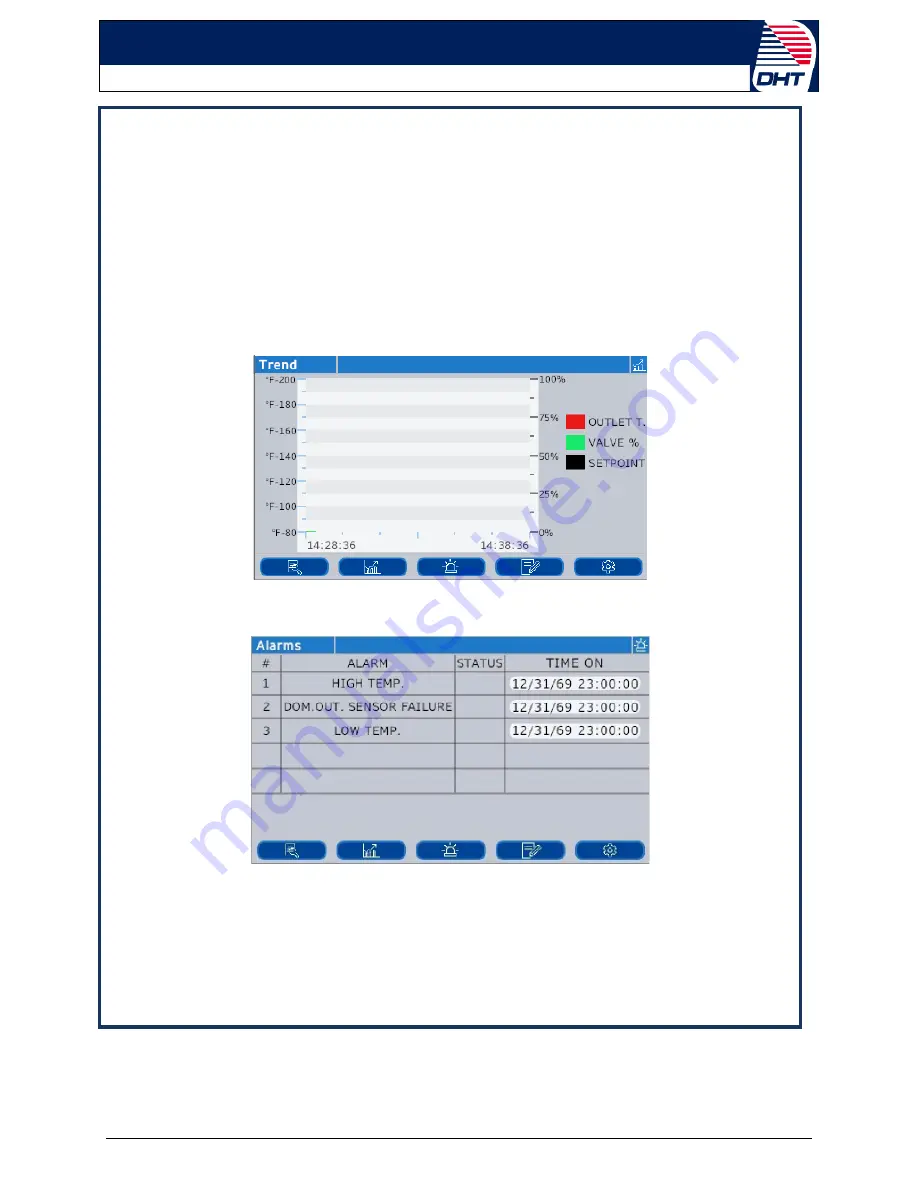
The “Trend screen” shown below displays the real-time trend graphs of domestic outlet & 
inlet water temperatures, setpoint and control valve output open percentage as explained 
in Section 3.9.1 This screen is empty on the startup. It starts logging data and displaying 
graphs as soon as the unit is started.     


8. 

The “Alarms screen” shown below displays 

the status of the standard alarms, whether 

each alarm is active or not along with time and date when it occurred.  


9. 

The  “Contact  Information screen” shown below displays the DHT factory and local sales 
representative company contact information  as well as the serial number information of 
controller and water heater,  which are preconfigured before unit is shipped from factory. 
Each unit is factory configured to display appropriate information on this screen.  

Содержание STP Series

Страница 1: ... no warranty of any kind in respect to this material including but not limited to implied warranties of merchantability and fitness for a particular application DHT is not liable for errors appearing in this document nor for incidental or consequential damages occurring in connection with the furnishing performance or use of these materials This manual applies to the following units Simplex STP un...

Страница 2: ... INSTALLATION CLEARANCES AND UNIT DIMENSIONS 12 2 4 UNIT PLACEMENT 14 2 5 PIPING INSTALLATION AND UNIT CONNECTIONS 15 2 6 ELECTRICAL CONNECTIONS 16 2 7 WATER QUALITY 17 SECTION 3 OPERATION AND CONTROLS 18 3 1 INTRODUCTION 18 3 2 STP SERIES FUNCTIONAL DESCRIPTION 18 3 2 1 Brazed Plate Heat Exchanger Construction 20 3 3 PLATE OPTIONS 21 3 3 1 Double Wall Construction and Protection Performance 21 3 ...

Страница 3: ...ER CONNECTION REWIRING 56 4 3 HEAT EXCHANGER MAINTENANCE 57 4 3 1 General Heat Exchanger Maintenance Procedures 57 4 3 2 Clean In Place CIP Cleaning of Brazed Plate Heat Exchanger s 57 4 3 3 Brazed Plate Heat Exchanger Module Replacement 59 4 4 T P OR ADJUSTABLE RELIEF VALVE REPLACEMENT 60 4 5 BOILER WATER CONTROL VALVE OPTION MAINTENANCE 61 4 5 1 Control Valve Maintenance 61 4 5 2 Control Valve R...

Страница 4: ...PTION The Diversified Heat Transfer STP Series water heaters are engineered solutions for facility owners managers who need fully packaged storage type water to water heat transfer solution for quick and easy single point connections Storage tanks are constructed of either optional carbon steel with double glass lining or duplex stainless steel materials Heat exchangers are standard brazed plate d...

Страница 5: ... system with components engineered to standard application requirements for single point connections Energy efficient High recovery Double Wall Brazed Plate stainless steel construction heat exchanger ASME compliance heat exchanger and storage tank 1 4 APPLICATIONS STP Series units are used in wide range of domestic water heating applications including either new construction or replacement of exi...

Страница 6: ...struction depending upon customer requirement Carbon steel tank configuration also includes consumable anodes Optional powered anodes are also available for maintenance free operation by preventing corrosion of the tank and anodes are not consumed Dispersion tubes are installed inside storage tank on brazed plate heat exchangers inlet and outlet connections which helps to prevent mixing of hot and...

Страница 7: ...DHT Pressure and temperatures should not exceed limits indicated on the DHT name plate attached to the unit For initial startup refer to all instructions in Section 3 7 Unit Startup Procedures The heating and heated fluids should be free from any debris The unit should operate only with fluid thatit was designed for The system should be designed to prevent the unit from encountering pressure shock...

Страница 8: ...azard that WILL lead to injury or death 1 8 5 Proper Training Proper training is the best protection against accidents Operating and service personnel must be thoroughly familiar with the basic construction and operation of the STP Series storage water heater and all applicable safety precautions If any of the provisions of this manual are not fully and completely understood contact DHT technical ...

Страница 9: ...ng to perform any maintenance on the unit shut off all electrical power to the unit from an exterior switch Electrical voltages up to 120 VAC may be used in this equipment therefore the front panel door on the unit s power box must be closed at all times except during maintenance and servicing A three pole switch must be installed on the electrical supply line of the unit The switch must be instal...

Страница 10: ...NS TO AVOID A DANGEROUS SITUATION Startup and installation forms MUST be submitted to a DHT representative or risk loss of coverage under warranty The inspection log must be maintained and up to date and kept in close proximity to the STP Series unit for inspection of DHT personnel NOTE The startup must be performed by DHT factory personnel or a factory authorized representative 2 1 RECEIVING HAND...

Страница 11: ...es water heater is constructed and stamped in accordance with ASME Boiler and Pressure Vessel Code Section VIII Division 1 for heat exchanger s and ASME Section IV part HLW Code for storage tank Other codes or approvals which apply will be labeled on the STP Series water heater The STP Series water heater installation must be performed only by technically qualified persons The installation must co...

Страница 12: ...earances are shown in Figure 2 1 and dimensions are shown in Figure 2 2 The minimum clearance dimensions are indicated in the drawings However if local building codes require additional clearances the local building codes shall supersede these requirements Consult factory for any specific questions All water piping and electrical conduit or cable must be arranged so that they do not interfere with...

Страница 13: ...Manual SECTION 2 INSTALLATION INSTRUCTIONS Rev 1 Diversified Heat Transfer Inc 439 Main Road Route 202 Towaco New Jersey 07082 Page 13 of 97 STP Manual PHONE 800 221 1522 WEBSITE www dhtnet com 09 11 2019 FIGURE 2 2 STP Series Dimensional Drawing ...

Страница 14: ...l construction following DHT guidelines and applicable architectural and local code requirements to assure the safe operation of the unit NOTES 1 Proper rigging techniques should be followed while moving heavy equipment 2 Maintain proper levels in order for the unit to function properly and follow clearance dimensional and applicable drawings CAUTION Refer to Section 2 5 Piping Installation and Un...

Страница 15: ...ion piping shall be properly sized to provide sufficient capacity to dissipate residual heat within the water heaters during the periods of low demand Boiler water piping Boiler water inlet and return piping to be sized per given flow rates to the control valve or VFD pump options CAUTION High temperature water can present a very dangerous situation because of the high pressures and temperatures F...

Страница 16: ...odes Connect the system to the correct voltage The STP Series water heater requires 120V AC 15Amp service with ground H N G supplied from a suitable circuit breaker or fused disconnect The circulation pump has a 120V constant speed fractional HP motor that operates continuously when the power to the unit is on Refer to Section 6 4 for standard electrical wiring drawings schematics terminal block c...

Страница 17: ... systems that are prone to trap air pockets Consider using water hammer arrestors or an expansion tank to dampen the spikes in water pressure since water hammering can lead to premature failure of the unit Water hardness contributes to the formation of scaling which impacts the performance of the unit components and may lead to their premature failure Water hardness should not exceed 6 grains per ...

Страница 18: ...sensor installed on the storage tank transmitting a millivolt signal to PID controller which in turn sends a 4 20 MA signal to the optional electrically activated control valves or VFD pumps to achieve accurate temperature control over various demand situations The STP Series can efficiently produce higher flow domestic hot water depending upon the temperature rise and available boiler water tempe...

Страница 19: ... lining or optional duplex stainless steel materials of construction Carbon steel tank configuration also includes consumable anodes or optional powered anodes for maintenance free operation by preventing corrosion of the tank Diverter tubes also called dispersion tubes are installed inside storage tank on both cold and hot water inlet connections which helps to prevent mixing of hot and cold dome...

Страница 20: ... work the same way as plate and frame heat exchangers and can come configured in a number of ways Brazed plate heat exchangers are constructed as modules in the configuration desired They can be cleaned with cleaning agents and Clean In Place procedures but are not disassembled for maintenance or plate replacement They are replaced at the effective end of service life CONTROL PANEL BRAZED PLATE HE...

Страница 21: ...ance Fully visible and vented leak detection between plates Potable water and heating medium are completely separated Leakage can be caused by corrosion erosion and vibration and can result in the domestic water system being contaminated by a heating medium such as hydronic water glycol solution etc There is no practical way to have the heating medium sterile or free from harmful treatment compoun...

Страница 22: ...and then alarm starts sounding In the next step the power supply to the control valve is interrupted causing it to close Hot water outlet piping includes pressure and temperature relief valve to release high temperature hot water to safe drain in order to protect the unit When the unit goes back to normal operating temperature conditions a green light turns on but the siren continues until the own...

Страница 23: ...g and closing with respect to signal from the controller Control Valve is factory set to Automatic mode of operation Control Valve is powered by 24VAC electricity Control Valve is actuated by 4 to 20 mA signal from the controller o 4mA means valve is in fully closed position Means flow path from port A to AB is closed when valve is de energized fail safe feature o 20mA means valve is in full open ...

Страница 24: ...e The Control Valve Automatic and Manual control modes can be selected using the knob shown in Figure 3 6 FIGURE 3 6 Selecting AUTO or MANUAL Control 3 5 3 1 AUTO Control The control signal is converted by the microprocessor in the electronics module into an output signal that generates a magnetic field in the core This causes the only moving part the armature to change its position in accordance ...

Страница 25: ...ure 3 6 inward and turn it counterclockwise to the OFF position The valve will close For automatic control the knob Fig 3 6 must be set to the AUTO position knob will spring out WARNING The valve knob Figure 3 6 MUST be set to AUTO position for proper orientation of the STP Series unit 3 5 4 Controller Status LED Indication Open the electronics module of the Controller Valve to view the two color ...

Страница 26: ...mbined with the intuitive user interface allow for quick start ups achieving optimum system efficiency and maximum comfort It is available in standard Cast Iron material construction for closed loop boiler water flow control through heat exchanger s FIGURE 3 8 VFD Pump with Flange Connections 3 6 1 Performance Data STP Series water heaters include optional VFD pumps which are simple to install and...

Страница 27: ...s following easy to set operating mode options o Constant speed 3 modes o Constant pressure 4 modes o Proportional Pressure o 0 10V o 2 Pump Alteration WARNING The pump is factory set to 0 10V operation and should remain in this mode for proper operation of the unit Unit controls include conversion from 4 20mA signal to 0 10V mode operation for this option 3 6 3 Pump Installation Piping assembly s...

Страница 28: ...ithin the enclosure Installation or service should be carried out only by trained personnel 3 6 4 Controller Status LED Indication and Error Codes LED Status monitors Pump On solid green for normal operation and Standby flashing green The pump Status LED will flash red during errors and overload conditions The sequence of the flash is determined by the type of error as shown in following table Err...

Страница 29: ...the boiler water HTHW return valve 6 If no leaks are found slowly open the manual shutoff valves on the energy source inlet NOTE This procedure is similar for both boiler water and high temperature water energy sources CAUTION Boiler water and high temperature water present situations that can be very dangerous because of the high temperatures and pressures Use common sense and follow all accepted...

Страница 30: ...ectric control 3 When possible relieve the pressure from energy source line boiler water or high temperature water between the shutoff valve and the unit 4 Wait 5 minutes or until dial thermometer starts dropping Close all remaining valves in the system in this order a Hot water outlet line b Cold water inlet line c Boiler high temperature water return line 5 After the system has cooled drain the ...

Страница 31: ...SERIES STARTUP SHUTDOWN COMPONENTS NOTE Also refer to appropriate drawings in Section 6 for more installation instructions and other field installed component location details CONTROL PANEL BRAZED PLATE HEAT EXCHANGERS ADJUSTABLE RELIEF VALVE ON BOTH UNITS DRAIN VALVE CLEANING PORT ON BOTH UNITS HOT WATER OUTLET T P RELIEF VALVE INSULATED STORAGE TANK TEMPERATURE SENSOR OR AQUASTAT ISOLATION VALVE...

Страница 32: ...reen menus Backup interface on PID controller display is also available behind the front door when front HMI interface is down Standard communication between HMI and PID controller is through MODBUS RTU protocol Utilizes 1 8 DIN advanced programmable PID temperature controller factory configured for full range of math logic totalizer and specialized functions required for single loop process and t...

Страница 33: ...date time when an alarm condition is triggered Logged data is automatically exported after USB memory drive is inserted in its slot behind HMI for a backup memory or an external storage in a txt format Contact Info Screen displays the DHT factory and local sales representative company address and contact information in plain English format for ease of access Unit and controls serial number informa...

Страница 34: ...ttons Temperature Controller has six buttons four navigation and two function available as shown in following button layout Button Operation Raise The raise button increments parameter values to limits Lower The lower button decrements parameter values to limits Page In Operator levels 1 or 2 the Page button will select between the Home display or the Programmer Edit and Run lists if one of the pr...

Страница 35: ...hrough parameters from bottom to top with auto repeat Page Scroll all variants Jump directly to the HOME page The current operating level remains unchanged If the HOME page is already selected these buttons will perform the custom function The default is Alarm Acknowledge Raise Lower Run Hold If a programmer option is enabled and a program is configured a momentary press of these keys toggles betw...

Страница 36: ...trols main touchscreen display is shown below STP SERIES CONTROL PANEL FRONT Location of temperature controller is shown below which can be used as a backup interface when front HMI screen interface is down PID CONTROLLER LOCATION BEHIND THE FRONT DOOR Upon power up the opening screen on touchscreen shows the DHT logo and then defaults to the display HOME screen below TEMPERATURE CONTROLLER TOUCHS...

Страница 37: ... PHONE 800 221 1522 WEBSITE www dhtnet com 09 11 2019 NOTE The setpoint shown in this section is for information purposes only User has to manually adjust the number depending upon required application operating conditions following the programming sequence in Section 3 11 DEFAULT STP SERIES HOME SCREEN To program the controller for operation follow the instructions in the following sections ...

Страница 38: ...applies to logout within a timeout period default is 30 min and the controller automatically logs out to save the recent setting adjustments DISPLAY SCREENS AND ADJUSTMENTS 3 The STP Series default HOME screen as explained in Section 3 9 1 Factory default domestic hot water set point is 140 F This screen shows the adjustable domestic water set point as well as currently measured domestic outlet te...

Страница 39: ... flashing in red color on the center top side of the HOME screen This merely serves as a warning that unit is not able to maintain the target setpoint 7 The Trend screen shown below displays the real time trend graphs of domestic outlet inlet water temperatures setpoint and control valve output open percentage as explained in Section 3 9 1 This screen is empty on the startup It starts logging data...

Страница 40: ...of the screen 13 Click on Leave Config at the bottom of this screen which then defaults to home screen NOTES 1 Not recommended to use manual positioning when unit is in operation Always leave the unit in AUTO Automatic setting 2 Valve shows the live output percentage signal to the control valve 3 There are three more screens available under settings which are higher level password protected in ord...

Страница 41: ...owaco New Jersey 07082 Page 41 of 97 STP Manual PHONE 800 221 1522 WEBSITE www dhtnet com 09 11 2019 NOTES 1 Sometimes loose wiring connections can also cause these error conditions which can be easily cleared by making proper connections 2 If error condition still exists contact sales representative or DHT technical support for more information ...

Страница 42: ...ay Optional gateway is also available for communications with other protocols Communication between HMI and Temperature controller is standard Modbus RTU Use RJ45 port to connect PC or network computer system with PID controller WARNING Maximum communication cable lengths without repeater RS485 Network 4 000 feet Ethernet Network 328 feet Communications and power wiring should never be routed toge...

Страница 43: ...isabled by default as enabled service makes it easier for a malicious user to discover and access the controller via the network c DHCP Mode i Default OFF ii Enabling DHCP will auto configure IP address Subnet Masks default gateway iii Dynamic IP addressing d Static Mode i Default ON ii User can manually set up IP address Subnet Masks default gateway 2 Ability to connect through Modbus RTU protoco...

Страница 44: ...ified Heat Transfer Inc 439 Main Road Towaco New Jersey 07082 Rev 1 09 11 2019 PHONE 800 221 1522 WEBSITE www dhtnet com STP Manual 3 13 4 Modbus RTU Communication Wiring NOTE Up to 32 units can be connected in a daisy chain network including BAS Master Single unit wiring Multiple units daisy chain wiring ...

Страница 45: ...180 F Range 140 F Default Unit Remote On Off float32 277 Analog Value 53 RW 0 Off 1 On Outlet Water Temperature float32 289 Analog Input 1 RO 40 205 F Range Control Valve Open age float32 4 Analog Input 10 RO 0 100 Range High Temperature Alarm Status bool 2149 Binary Input 10 RO 0 Off 1 On Default 20 F above Setpoint Low Temperature Alarm Status bool 2245 Binary Input 14 RO 0 Off 1 On Default 20 F...

Страница 46: ...nu while the controller is operating the water heater Do not power off the controller without completing all the steps in the configuration settings Save and go back to the main screen Configurations settings shall be performed only by trained and experienced personnel Proper care must be taken to prevent any changes to other settings in the configurations Refer to following steps 1 Open the front...

Страница 47: ...22 WEBSITE www dhtnet com 09 11 2019 3 Now release the button Again press and hold page button until following screen appears 4 Use raise and lower buttons in the next step to navigate to the following screen 5 Click on scroll button and you will see passcode screen as shown below 6 Click on scroll button again to move to the next digit and use arrow buttons to select the passcode The default pass...

Страница 48: ...Transfer Inc 439 Main Road Towaco New Jersey 07082 Rev 1 09 11 2019 PHONE 800 221 1522 WEBSITE www dhtnet com STP Manual 7 If the entered passcode is correct it will direct to configuration menu screen 8 Now click on page button and you will see following screen 9 Click on page button until COmm appears on the screen ...

Страница 49: ...Modbus BACnet IP settings refer to steps 13 through 25 Ignore steps 11 and 12 below 11 Click on scroll button and you will see F COm From the sub menu you are able to set up the parameters for Modbus RTU 12 Now click on scroll button and then click on raise button to select Then click on scroll and you will see the following parameters for Modbus RTU a Default Baud rate 19200 b Click on scroll but...

Страница 50: ...22 WEBSITE www dhtnet com STP Manual 13 Click on scroll button and you will see mAIN screen 14 Click on raise button to select then click on scroll button and you will see Auto discovery mode Default is OFF 15 Click on to move to the IP MODE Use arrow button to switch the mode a is static mode IP Gateway Subnet masks shall be manually setup b is DHCP mode DHCP server shall be setup to assign IP et...

Страница 51: ...e the screen a b Use arrow buttons to change the IP addresses if required 17 Continue to click to see subnet masks Indicator IP S1 IP S2 IP S3 IP S4 a Use arrow buttons to change the subnet masks if required 18 Continue to click to see default gateway Indicator IP G1 IP G2 IP G3 IP G4 a Use arrow buttons to change the default gateway if required 19 Continue to click on to see mac addresses 20 Afte...

Страница 52: ...9 11 2019 PHONE 800 221 1522 WEBSITE www dhtnet com STP Manual 22 Click to see parameter device ID for BACnet Use the arrow buttons to change device ID if required 23 After the setup is complete press and hold button until the following screen appears 24 Click on to go back to the main screen and the settings will be saved 25 Now the controller is ready for normal operation ...

Страница 53: ... This input is supplied with the current transformer Contact closure on the remote switch disable stop the unit 3 14 2 Fault Relay Contacts Fault relay R1 terminals 11 and 14 shown below also shown in Section 6 4 available on the terminal block inside the control panel box for remote alarm indication purposes This relay is a Double Pole Double Throw DPDT type which energizes when fault condition o...

Страница 54: ...ical parts and components Any questions concerning maintenance procedures should be directed to DHT support at 1 800 221 1522 Please be prepared with model and serial numbers of the unit prior to contacting DHT NOTE Taking the unit offline is required for many of the maintenance procedures in this section so all technicians performing maintenance should be familiar with the procedures necessary fo...

Страница 55: ... to be defective or worn replace the pump per the following steps c After assuring that the power has been turned off disconnect the electric leads to the circulating pump d Drain the unit by opening the drain valves See Figures 3 1a and 3 1b e Break the flanged joint between the pump and the inlet and outlet piping f Remove the pump g Reconnect the pump to the inlet and outlet piping Follow recom...

Страница 56: ... CONNECTION REWIRING INSTRUCTIONS 1 Follow Steps 1 through 5 of the shutdown procedure Sec 3 8 to take the unit offline before attempting any electrical service WARNING TURN OFF DISCONNECT ALL ELECTRIC POWER BEFORE ATTEMPTING ANY MAINTENANCE PROCEDURE 2 After assuring the power has been turned off disconnect and rewire the electrical connection in question Refer to Section 6 4 for wiring details 3...

Страница 57: ...eat exchanger life is improved Information for cleaning solutions is listed below FLUID TYPE INFORMATION Mineral Acids They have highest ability to dissolve scale limestone and other minerals but are also extremely hazardous Examples include hydrochloric HCl sulfamic nitric phosphoric and sulfuric acids Hydrochloric acid and nitric acid cause corrosion of stainless steel and copper materials respe...

Страница 58: ...The cleaning agent should be circulated through the system at the fastest flow rate available 10 to 20 above normal but at the least should be at the normal operational flow rate 4 Circulate the cleaning solution for at least 30 minutes and up to 4 to 6 hours If possible reverse the flow direction every 30 minutes 5 After the cleaning interval always rinse the system thoroughly with fresh water Ci...

Страница 59: ...re to bleed all pressure from all parts of the unit Open the drain valves 4 Make sure the heat exchanger cools down to safe temperatures 5 Remove the four bolts that affix the module to the support plate 6 Decouple the all the four water connections to the heat exchanger module 7 Replace the module recouple to the four water heater connections and affix the four bracket nuts 8 After all adjustment...

Страница 60: ...NTENANCE PROCEDURE 2 Carefully disconnect the drain line from the relief valve to the drain 3 Unscrew and remove the relief valve from its mounting location Fig 4 4 4 Install the new relief valve in place Tighten until sealed and facing proper orientation for reconnection to the drain line NOTE Use and type of joint sealer should be determined from local codes or the specifications of the installi...

Страница 61: ...s of the valve See the table below to determine if the valve may possibly be faulty 3 WAY CONTROL VALVE STATUS LEDs LED Display Status Description Green LED On continuously Automatic mode Auto normal no faults Flashing Mechanically set to MANUAL Mechanically set to OFF Currently in auto calibration mode Red LED On continuously General fault General calibration fault Microcontroller fault Flashing ...

Страница 62: ...CEDURE 2 Assure that the energy source water inlets and outlets have been shut off that the pressure has been bled from the energy source hot water system that the unit has been completely drained and that all components and surfaces have cooled 3 Turn off the power and disconnect the leads to the valve 4 Carefully break all connections to the control valve and remove the old valve from the unit W...

Страница 63: ...ent instructions etc contained in the pump manufacturer s documentation shipped with the unit VFD PUMP INSPECTION AND REPLACEMENT INSTRUCTIONS a Take the unit offline Steps 1 through 5 of the shutdown procedure Sec 3 9 before attempting to service the circulating pump WARNING TURN OFF DISCONNECT ALL ELECTRIC POWER BEFORE ATTEMPTING ANY MAINTENANCE PROCEDURE b Test the pump according to manufacture...

Страница 64: ...ceable by personnel trained certified on DHT Inc STP water heaters The replaceable parts may vary depending on the unit and the particular design specifications in which the unit was constructed If there are questions concerning the replaceable parts for the unit refer to the original design specifications or contact DHT Inc Please have the unit s model and serial number available when contacting ...

Страница 65: ...rmocouple or Aquastat SEC 4 12 1 T P Relief Valve SEC 4 12 1 or 2 Adjustable Relief Valve SEC 4 12 1 or 2 Anode s only with carbon steel tank 4 10 ORDERING INFORMATION All replacement parts for DHT STP Series units can be ordered directly from your local authorized sales representative agent Visit Rep Locator page on DHT website if needed to find your local sales rep contact information NOTE If sa...

Страница 66: ...eater components inlet and outlet water and energy source lines boiler water or high temperature water and power connections TABLE 4 4 RECOMMENDED INSPECTIONS TIME INTERVAL TABLE TO BE INSPECTED PER MANUFACTURE SPECS WEEKLY MONTHLY 3 MONTHS 6 MONTHS 1 YEAR Circulation Pumps X Control Valve or VFD Pump X Temperature and Pressure Gauges X Heat Exchanger measure performance X All Inlet Outlet and Ret...

Страница 67: ...SSORIES TABLE 4 5 PLATE AND FRAME BRAZED PLATE UNITS ITEM NO PART NO QUANTITY PART DESCRIPTION 1 SEE TABLE 4 6 1 STORAGE TANK 2 SEE TABLE 4 7 1 INSULATION JACKET 3 SEE TABLE 4 8 1 SIMPLEX 2 DUPLEX BRAZED PLATE HEAT EXCHANGER 4 64002 2 1 CONTROL PANEL OPTIONAL 64003 1 RELAY CONTROL BOX OPTIONAL WITH AQUASTAT CONTROL MHRD 03 0013 4 HEX BOLT 1 4 20 X 0 75 LG FULL THREAD UNC 2A MHRD 05 0001 FLAT WASHE...

Страница 68: ...LANGE 2 V 0300 0607 2 DUPLEX ONLY 3 VICTAULIC COUPLING 11 MPART E BV 0106 1 SIMPLEX 2 DUPLEX BALL VALVE FULL PORT 2 SWEAT LEAD FREE 12 22003 1 SIMPLEX 2 DUPLEX PRESSURE RELIEF VALVE 1 2 NPT 13 72005 5 1 SIMPLEX 2 DUPLEX BRASS PLUG 1 2 NPT 14 MHRD 01A 2001 4 FLANGED LOCKNUT 1 2 13 UNC GRADE 5 15 40008 2 1 SIMPLEX 2 DUPLEX HEAT EXCHANGER BRACKET FOR SMALL SIZE 40008 1 HEAT EXCHANGER BRACKET FOR LARG...

Страница 69: ...TANK 210 GALLON DOUBLE GLASS LINED C S 85002 285GL TANK 285 GALLON DOUBLE GLASS LINED C S 85002 453GL TANK 453 GALLON DOUBLE GLASS LINED C S 85002 500GL TANK 500 GALLON DOUBLE GLASS LINED C S 85002 765GL TANK 765 GALLON DOUBLE GLASS LINED C S TABLE 4 7 INSULATION JACKET ITEM NO PART NO QUANTITY PART DESCRIPTION 2 20001 175 1 INSULATION JACKET 175 GALLONS TANK 20001 210 INSULATION JACKET 210 GALLON...

Страница 70: ... 10 CONTROL VALVE MODULE PARTS ITEM NO PART NO QUANTITY PART DESCRIPTION 21 MPART A MXV 0004 1 SIMPLEX 2 DUPLEX CONTROL VALVE 2 NPT 22 MFIT 5 S 2 2002 2 PIPE SPOOL 23 MFLG 2 V 0200 600 01 2 VICTAULIC COUPLING VFD PUMP OPTION PARTS TABLE 4 11 VFD PUMP MODULE PARTS ITEM NO PART NO QUANTITY PART DESCRIPTION 24 MELE 09 0103 1 SIMPLEX 2 DUPLEX VFD PUMP WITH STAINLESS COMPANION FLANGES 25 70006 1 50 SIZ...

Страница 71: ... SECTION 4 MAINTENANCE Rev 1 Diversified Heat Transfer Inc 439 Main Road Route 202 Towaco New Jersey 07082 Page 71 of 97 STP Manual PHONE 800 221 1522 WEBSITE www dhtnet com 09 11 2019 4 13 CONTROL BOX PARTS 1 2 3 4 5 6 7 8 9 10 11 12 13 14 15 16 17 18 ...

Страница 72: ...LE 19 0003 1 HMI COM I F CONNECTOR 4 MELE 19 0004 1 HMI INSTALLATION FASTENERS KIT 5 MELE 19 0005 1 HMI BATTERY KIT 6 MELE 19 0006 1 ALARM SILENCE PUSHBUTTON 7 MELE 19 0007 1 SOUND ALARM BUZZER 8 MELE 19 0008 1 TEMPERATURE CONTROLLER 9 MELE 19 0009 1 TEMPERATURE CONTROLLER MOUNTING CLIPS KIT 10 MELE 19 0010 1 POWER ON OFF SELECTOR SWITCH MELE 19 0011 1 GREEN LED WITH N O CONTACT 11 MELE 19 0012 1 ...

Страница 73: ...MELE 19 0019 9 DOUBLE HIGH TERMINAL BLOCKS 17 MELE 19 0020 1 DOUBLE HIGH GROUND TERMINAL BLOCK 18 MELE 19 0021 4 END ANCHORS 19 MELE 19 0022 1 CONTROL PANEL ENCLOSURE ASSEMBLY 20 MELE 19 0023 1 HINGED FRONT PANEL KIT 21 MELE 19 0024 1 HINGED PANEL HARDWARE REPLACEMENT KIT 22 MELE 19 0025 1 FRONT COVER 23 MELE 19 0026 1 STAINLESS STEEL HINGE PIN 24 MELE 19 0027 2 STAINLESS STEEL LATCH FOR ENCLOSURE...

Страница 74: ...d Maintenance Manual SECTION 4 MAINTENANCE Page 74 of 97 Diversified Heat Transfer Inc 439 Main Road Towaco New Jersey 07082 Rev 1 09 11 2019 PHONE 800 221 1522 WEBSITE www dhtnet com STP Manual This page is intentionally left blank ...

Страница 75: ... required temperature Refer to programming sequence in section 3 12 for complete settings information 2 See the adjustment and testing instructions contained in the supplied Installation Operations Manual Repair or replace the valve if necessary Refer to Sections 3 5 and 4 5 for Control Valve and Sections 3 6 and 4 6 for VFD Pump Technical Information if hard copy is not available Make sure is is ...

Страница 76: ...authorized representative for instructions on repair or replacement if necessary Also ensure the water quality levels are within the allowable limits 6 Check the pump s on off and high low temperature settings Inspect and replace the relay switch if not functioning properly DHW supply outlet temperature fluctuates significantly 1 Control Valve or VFD pump does not open close properly 2 Water heate...

Страница 77: ...Open the valve or pump cover and check 4 20mA control signal is present at terminals 4 20mA converted to 2 10VDC for pump Troubleshoot panel to restore proper signal to control valve or VFD pump if it malfunctions Also check control valve dip switches or pump controller settings as shown in Section 6 4 Temperature and Pressure or pressure only relief valve pops 1 Control Valve or VFD pump does not...

Страница 78: ...lso check to make sure there is no restriction in the water return line Replace the check valve if it is leaking or has failed 2 Install the properly sized expansion tank in the closed loop piping system as shown in Installation and Piping drawings in Section 6 3 3 In order to avoid any shock waves install water hammer arrestors shock absorbers in the hot and cold water systems as needed Also chec...

Страница 79: ...ains at zero or shows no change but the process is changing 1 Recycle power to the unit by removing AC power waiting 10 seconds and reconnecting power If the problem persists contact the local DHT representative Entire System is OFF 2 External 120V AC power disconnected or ON OFF switch on control panel failed OFF 2 Check to make sure external circuit breaker is ON and there is power supply availa...

Страница 80: ...l SECTION 6 TECHNICAL DRAWINGS AND FORMS Page 80 of 97 Diversified Heat Transfer Inc 439 Main Road Towaco New Jersey 07082 Rev 1 09 11 2019 PHONE 800 221 1522 WEBSITE www dhtnet com STP Manual SECTION 6 TECHNICAL DRAWINGS FORMS 6 1 DIMENSIONAL DRAWINGS ...

Страница 81: ...tenance Manual SECTION 6 TECHNICAL DRAWINGS AND FORMS Rev 1 Diversified Heat Transfer Inc 439 Main Road Route 202 Towaco New Jersey 07082 Page 81 of 97 STP Manual PHONE 800 221 1522 WEBSITE www dhtnet com 09 11 2019 6 2 CLEARANCE DRAWINGS ...

Страница 82: ...nance Manual SECTION 6 TECHNICAL DRAWINGS AND FORMS Page 82 of 97 Diversified Heat Transfer Inc 439 Main Road Towaco New Jersey 07082 Rev 1 09 11 2019 PHONE 800 221 1522 WEBSITE www dhtnet com STP Manual 6 3 PIPING AND INSTALLATION DRAWINGS ...

Страница 83: ...ion and Maintenance Manual SECTION 6 TECHNICAL DRAWINGS AND FORMS Rev 1 Diversified Heat Transfer Inc 439 Main Road Route 202 Towaco New Jersey 07082 Page 83 of 97 STP Manual PHONE 800 221 1522 WEBSITE www dhtnet com 09 11 2019 ...

Страница 84: ...HNICAL DRAWINGS AND FORMS Page 84 of 97 Diversified Heat Transfer Inc 439 Main Road Towaco New Jersey 07082 Rev 1 09 11 2019 PHONE 800 221 1522 WEBSITE www dhtnet com STP Manual 6 4 ELECTRICAL WIRING DIAGRAMS SCHEMATICS Control Box Internal Electrical Wiring Diagram ...

Страница 85: ...ce Manual SECTION 6 TECHNICAL DRAWINGS AND FORMS Rev 1 Diversified Heat Transfer Inc 439 Main Road Route 202 Towaco New Jersey 07082 Page 85 of 97 STP Manual PHONE 800 221 1522 WEBSITE www dhtnet com 09 11 2019 Terminal Block Wiring Connections ...

Страница 86: ...gnal conversion with 500 ohm resistor Electrical Power Supply Connections Open the electrical module cover on side of the pump to make 200 240V 1ph 60Hz wiring connections NOTES Connect the black wire of the pump to the hot live wire and white wire to neutral Ground wire is connected to the green color screw as shown above Power supply cabling should be capable of carrying rated power and be prope...

Страница 87: ...00 221 1522 WEBSITE www dhtnet com 09 11 2019 Relay Panel Wiring Schematic with Aquastat Control Option Field Wiring Connections for Relay Panel NOTES Unit shuts down upon loss of electrical Power supply cabling should be capable of carrying rated power and be properly fused Install external electrical disconnect complying with electrical codes National or local electrical codes supersede the inst...

Страница 88: ...22 WEBSITE www dhtnet com STP Manual 6 5 FORMS AND RECORDS 6 5 1 DHT Water Heater Controller Programming Record Sheet DHT Water Heater Controller Programming Record Sheet MODEL NUMBER SERIAL NUMBER VERSION PASSWORD SETPOINTS SETPOINT PRIMARY ALARM ON AT PRIMARY ALARM OFF AT SECONDARY ALARM ON AT SECONDARY ALARM OFF AT PASSWORD INPUT FILTER UNIT TEXT SCALING DECIMAL POINT ANALOG INPUT LOW ANALOG IN...

Страница 89: ...nce Manual SECTION 6 TECHNICAL DRAWINGS FORMS Rev 1 Diversified Heat Transfer Inc 439 Main Road Route 202 Towaco New Jersey 07082 Page 89 of 97 STP Manual PHONE 800 221 1522 WEBSITE www dhtnet com 09 11 2019 6 5 2 STP Series Installation Form ...

Страница 90: ... Operation and Maintenance Manual SECTION 6 TECHNICAL DRAWINGS FORMS Page 90 of 97 Diversified Heat Transfer Inc 439 Main Road Towaco New Jersey 07082 Rev 1 09 11 2019 PHONE 800 221 1522 WEBSITE www dhtnet com STP Manual ...

Страница 91: ...ation and Maintenance Manual SECTION 6 TECHNICAL DRAWINGS FORMS Rev 1 Diversified Heat Transfer Inc 439 Main Road Route 202 Towaco New Jersey 07082 Page 91 of 97 STP Manual PHONE 800 221 1522 WEBSITE www dhtnet com 09 11 2019 ...

Страница 92: ... Operation and Maintenance Manual SECTION 6 TECHNICAL DRAWINGS FORMS Page 92 of 97 Diversified Heat Transfer Inc 439 Main Road Towaco New Jersey 07082 Rev 1 09 11 2019 PHONE 800 221 1522 WEBSITE www dhtnet com STP Manual ...

Страница 93: ...enance Manual SECTION 6 TECHNICAL DRAWINGS FORMS Rev 1 Diversified Heat Transfer Inc 439 Main Road Route 202 Towaco New Jersey 07082 Page 93 of 97 STP Manual PHONE 800 221 1522 WEBSITE www dhtnet com 09 11 2019 6 5 3 STP Series Startup Form ...

Страница 94: ... Operation and Maintenance Manual SECTION 6 TECHNICAL DRAWINGS FORMS Page 94 of 97 Diversified Heat Transfer Inc 439 Main Road Towaco New Jersey 07082 Rev 1 09 11 2019 PHONE 800 221 1522 WEBSITE www dhtnet com STP Manual ...

Страница 95: ...ecific Limited Warranty is limited to modify repair or exchange the defective item which after examination shall to Seller s own satisfaction be determined to have been defective at the time it was shipped In the event that a replacement is provided by Seller the defective item will become the property of Seller Any claims relating to this product shall be limited to the list price of the product ...

Страница 96: ... area or property caused by leakage or malfunction J INCIDENTAL SPECIAL OR CONSEQUENTIAL DAMAGES SUCH AS LOSS OF THE USE OF PRODUCTS FACILITIES OR PRODUCTION INCONVENIENCE LOSS OF TIME OR LABOR EXPENSE INVOLVED IN REPAIRING OR REPLACING THE ALLEGED DEFECTIVE PRODUCT K Costs associated with the replacement and or repair of the unit including any freight shipping or delivery charges any removal inst...

Страница 97: ...Road Route 202 Towaco New Jersey 07082 Page 97 of 97 STP Manual PHONE 800 221 1522 WEBSITE www dhtnet com 09 11 2019 Installation Operation and Maintenance Manual Change Log Date Description Changed By 09 11 2019 Initial release SS www dhtnet com ...

Отзывы: