


MPCQ Platinum Installation and Operation Manual
11
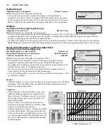
Wiring Network Sensors (Wireless and MIG)
(Requires Communication Package Upgrade)
• Remember that network sensors can only be configured remotely through the Internet
• The MPCQ Platinum Network terminals can connect to up to 64 network sensors.
• When connecting to multiple sensors, a Mini-MIG control can be used to handle up to
16 sensors each. Multiple MIG's can connect to a single MPCQ Platinum.
• Wireless sensors can be used with transceivers to reduce building sensor wiring. The
wireless Network Manager can be wired directly to the RS485 on the communication
board. The balance of the wireless system will communicate its information to the
wireless Network Manager.
• A variety of network sensors are available for the MPCQ Platinum:
◦ Stack sensor
◦ Count/Pulse sensor (connects to water meters.)
◦ Oil tank level sensor (OTM)
◦ Pressure, vacuum, and humidity transducers
◦ Wireless temperature sensors system
◦ Multiple Input Gateway (Mini-MIG) that gives the capability of connecting the
control to multiple temperature or switch sensors.
Platinum
Wireless
Network
Manager
Antena
MIG
Network
Network
Sensors
AUX
TEMP 0
AUX
TEMP 1
A10
A12
AUX
TEMP 2
A13
A14
A15
A16
A17
A18
NETWORK
PROVE
SHUTDOWN
OUT
TEMP
T
T
T
T
PRESS
4-20 mA
S
+
S
RS485
Mini-MIG
Multiple Input Gateway
Power
Comm
PWR
L N
1 2
Network
N1
3 4
Input 1
7
Input 2
9
Input 3
11
Input 4
13
Input 5
15
17
Input 7
19
Input 8
21
Input 6
10
12
14
16
18
20
22
Input 9
23
Input 10
25
Input 11
27
Input 12
29
Input 13
31
33
Input 15
35
Pulse
Input 16
37
Input 14
24
26
28
30
32
34
36
38
T1 T2 T3 T4
125 72 73 75
RESET
VIEW
8
0056789
Water
Meter
Stack
Sensor
Oil Level
Wiring Shutdown Terminals
• This feature can be used whenever it is desirable to turn off the MPCQ Platinum from
a remote location or another controller. A typical use for this feature would be to
disable all heat from an Energy Management System (EMS).
• When the Shutdown is enabled (by shorting the
Shutdown
input terminals, all stage
relays will de-energize. The System relay will continue to be energized for the Run-
On delay period.
• The Shutdown signal must be a dry contact only. No voltage can be placed across the
SHUTDOWN
terminals
- A3, A4
A2
A3
A4
A5
SHUTDOWN
TEMP
PRESS
S
Wiring Prove Terminals
• The Prove feature checks system components operation before activating any of the
boilers stages. It can be used to connect to the combustion air damper's end switch.
That way the system relay will energize the combustion air damper and the prove will
check if the damper is fully opened prior to activating any boiler stages.
• If the
PROVE
input terminals are open, the MPCQ Platinum will enable only the
System relay. All stage relays will be de-energized when the
PROVE
input is open.
• If NO external conditions are to be met before the stage relays are energized, DO
NOT remove the factory installed jumper across the
PROVE
terminals.
• The Prove signal must be a dry contact only. No voltage can be placed across the
PROVE
terminals
A9, A10
.
AUX
A8
A9
A10
A11
PROVE
T
WARNING
The
PROVE
input CANNOT be used as a safety limit. All equipment must have its own certified limit and safety
controls as required by local codes. Any safety interlock MUST be wired back to the boilers or other equipment as
required by code.
ALERT
The
PROVE
terminals must be shorted for MPCQ Platinum to provide heat. DO NOT remove the factory installed
PROVE jumper unless replacing it with a Prove signal.
Wiring Aux Input Terminals
(Requires Internet Communication Package Upgrade)
• Remember that Aux sensors can only be configured remotely through the Internet communication package.
• Each Aux terminal can connect to only one temperature (-30
°
F to 250F) or switch sensor.


