Heartland 16991 Скачать руководство пользователя страница 61

59

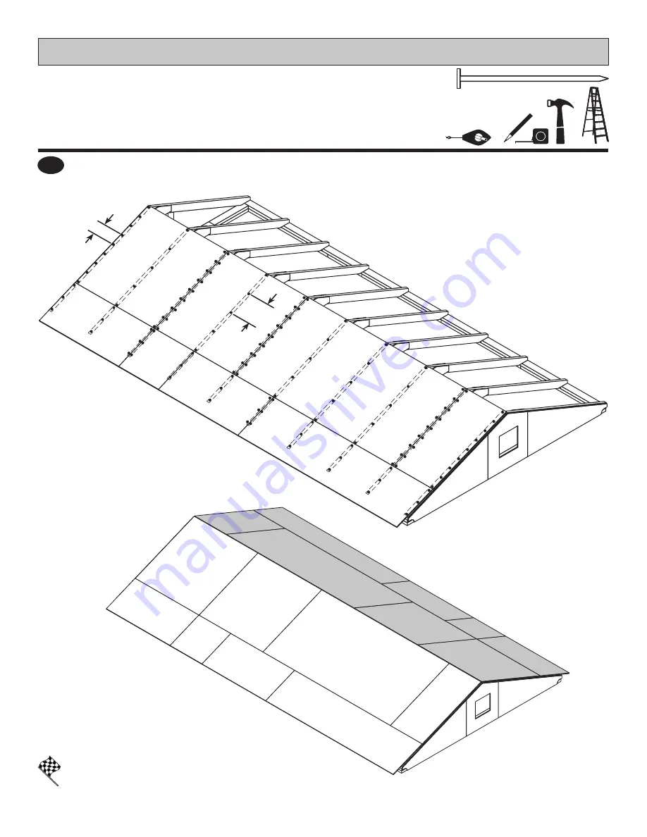
Your roof panels are now installed.

Repeat all steps to install roof panels 
on the opposite side.

FINISH

Secure all roof panels with 2" nails spaced 6" apart and 12" apart inside of the upper panels.

9

PARTS REQUIRED:

10' x 18' ROOF PANELS

2" (5,1 cm)

6" 

(15,2 cm)

    12"


(30,5 cm)

x230

Содержание 16991

Страница 1: ...AM AND MAKE UP TO 1 500 WEEK o r v i sit backyardinstaller c o m Flexible schedule No selling just building Bonus incentives available S c a n t he f lowcode to apply t o d a y INSTALLERS WANTED based on number of completed installations Call a Recruiter Today 734 365 7000 visit us online at help backyardproducts com AVOID THE WAIT Submit a help request Answers to frequently asked questions Live c...

Страница 2: ...DC Puerto Rico 18 or older to participate Taxes on prize are responsibility of winner Odds of winning depend on the number of eligible reviews received Void where prohibited For complete details and official rules visit https backyardreviews net sweepstakes rules Scan QR code above Click write a review Find your product Tell us what you think Submit your review You ll be notified by e mail if you ...

Страница 3: ...s before building ENGINEERED DRAWINGS Contact our Customer Service Team if engineered drawings are needed to pull local permits SURFACE PREPARATION To ensure proper assembly you must build your shed on a level surface Recommended methods and materials to level your shed are listed on page 10 CHECK ALL PARTS Inventory all parts listed on pages 5 8 ADDITIONAL MATERIALS You will need additional mater...

Страница 4: ... assembly or installation Level Gloves Framing lumber is graded for structural strength and not appearance Exterior trim is graded for one good side Always install the material leaving the best edge and best surface visible Please remember that these blemishes in no way negatively affect the strength or integrity of our product See Fig A B C A Safety Glasses Tape Measure Paint Tools Ladder Caulk G...

Страница 5: ...below as shaded Below is a list of additional materials not included x2 x3 x4 x8 x12 x16 2 x 4 x 10 5 1 x 10 2 x 304 8 cm Treated Lumber cut to 2 x 4 x 117 5 1 x 10 2 x 297 2 cm 3 7 6 cm hot dipped galvanized nails 2 x 4 x 10 5 1 x 10 2 x 304 8 cm Treated Lumber cut to 2 x 4 x 117 5 1 x 10 2 x 297 2 cm 2 x 4 x 10 5 1 x 10 2 x 304 8 cm Treated Lumber cut to 2 x 4 x 117 5 1 x 10 2 x 297 2 cm 3 7 6 c...

Страница 6: ...paintable latex exterior caulk 5 2 3 10x10 1 3 10x10 2 coats recommended Drip Edge Feet 15 Roofing Felt Sq ft to cover 1 Galvanized Roofing Nails lbs For roofing felt 2 5 1 cm 2 5 1 cm 2 5 1 cm x1 x2 x2 1 lb of 2 5 1 cm Hot Dipped Galvanized Box Type Nails 1 lb of 2 5 1 cm Hot Dipped Galvanized Box Type Nails 1 lb of 2 5 1 cm Hot Dipped Galvanized Box Type Nails 5 8 x 48 x 96 1 6 x 121 9 x 243 8 c...

Страница 7: ...61 cm x4 RL 2 x 4 x 20 3 8 5 1 x 10 2 x 51 8 cm x2 JBD 2 x 4 x 18 1 8 5 1 x 10 2 x 46 cm x4 AF 1 x 3 x 5 2 5 x 7 6 x 12 7 cm Used as a gauge block for 3 4 1 9 cm measurement x1 GAA AH x2 19 32 x 2 1 2 x 26 5 8 1 5 x 6 3 x 67 7 cm EU x2 19 32 x 2 1 2 x 17 1 6 x 7 6 x 43 2 cm DI x2 19 32 x 2 1 2 x 12 1 5 x 6 3 x 30 5 cm PARTS IDENTIFICATION AND SIZES Double letter part identification is stamped on s...

Страница 8: ...s are 7 16 1 1 cm thick Loft panels are 7 16 1 1 cm thick x2 x2 48 x 96 121 9 x 243 8 cm 23 1 2 x 96 59 7 x 243 8 cm x1 15 7 8 x 23 7 8 40 3 x 60 6 cm PANEL DOORS PARTS LIST x1 x1 x2 3 8 x 23 9 16 x 48 1 x 59 9 x 121 9 cm ROOF PANELS x2 x2 23 7 8 x 47 7 8 60 6 x 121 9 cm 23 1 2 x 23 7 8 59 7 x 60 6 cm LOFT PARTS LIST x1 23 7 8 x 96 60 6 x 243 8 cm 2 x 3 x 96 5 1 x 7 6 x 243 8 cm x1 PT 2 x 4 x 96 5...

Страница 9: ...1 x 7 6 x 25 4 cm 1 x 4 x 23 78 2 5 x 10 2 x 60 6 cm 3 8 x 8 x 12 1 2 1 x 20 3 x 32 cm 1 x 4 x 96 2 5 x 10 2 x 243 9 cm 7 16 x 11 7 8 x 23 7 8 1 1 x 30 2 x 60 6 cm 7 16 x 11 7 8 x 96 1 1 x 30 2 x 243 9 cm x12 x2 x12 x2 x2 x2 AC JS KP NAIL BOXES Shown Actual Size 3 7 6 cm 2 5 1 cm x5 BOXES x6 BOXES Shelf panels are 7 16 1 1 cm thick NOTE If you are using a nail gun nails may be used where screws ar...

Страница 10: ... 47 7 8 59 7 x 121 9 cm 47 7 8 x 48 121 6 x 121 9 cm 10 x 4 EXTENDER GABLE EXTENDER KIT PARTS LIST Inventory your parts before you begin We suggest sorting parts by the category they are listed in Part identification is stamped on some parts Check these locations for part stamp RS RS WOOD SIZE CONVERSION CHART Nominal Board Size Actual Size 1 x 4 3 4 x 3 1 2 1 9 x 8 9 cm 2 x 4 1 1 2 x 3 1 2 3 8 x ...

Страница 11: ...x10 304 8 x 304 8 cm 10 x 14 304 8 x 408 9 cm 10 x 18 304 8 x 548 6 cm 10 x10 304 8 x 304 8 cm 10 x14 304 8 x 408 9 cm 10 x18 304 8 x 548 6 cm 120 304 8 cm 169 11 16 476 1 cm 168 426 7 cm 216 548 6 cm 206 7 16 524 4 cm 247 1 8 627 7 cm 10 x 10 Building Requires 10 x 14 Building Requires 10 x 18 Building Requires 2 x 4 x 10 5 1 x 10 2 x 304 8 cm x2 2 x 4 x 10 5 1 x 10 2 x 287 cm x2 2 x 4 x 10 5 1 x...

Страница 12: ...x4 3 Screws shown as one option Minimum 3 screws exterior grade Measurements to centers of 4x4 s 12 30 5 cm 12 30 5 cm Use only wood treated for ground contact and fasteners approved for use with treated wood Always support frame seams Level under 4x4 runners only Locate leveling material 12 from ends of runners and no more than 48 apart Asphalt shingles should be used between 4x4 runners and bloc...

Страница 13: ... After the frame is level and square secure one side of frame to 4x4 runners using one fastener at ends of each runner At the opposite end of the frame secure the frame to 4x4 runners with one fastener at the ends of each runner ensuring that the frame remains square Fasten the frame to the 4x4 runners with 2 3 screws at each connection Fig A 2 BEGIN 1 Use a level and ensure the frame is level bef...

Страница 14: ...tion Organize your assembly procedure during the build process to avoid over handling of the walls HINT D O O R NOTE 10 x 10 Gable shown standard throughout manual Ensure the floor frame is level after installing floor panels Re level if needed EAVE WALL EAVE WALL EAVE WALL GABLE WALL GABLE WALL ...

Страница 15: ...installation 10 x 18 After assembling the walls for your 10 x 18 shed go to page 38 for wall installation 10 x 10 Wall 01 Page 16 Wall 02 Page 18 Wall 03 Page 20 Build 2 eave walls 10 x 14 Wall 01 Page 16 Wall 02 Page 18 Wall 04 Page 22 Build 2 eave walls 10 x 18 Wall 01 Page 16 Wall 02 Page 18 Wall 05 Page 24 Build 2 eave walls WALL INDEX 01 01 01 02 02 02 03 04 03 04 05 05 ...

Страница 16: ...d on flat surface flush in middle Center OSB on top of AM Fasten together with 3 nails in the pattern shown Your door header is now assembled FINISH OSB ASSEMBLED END VIEW BEGIN 1 AM AM 2 Flip header assembly over and nail as shown on the other side Flush Flush Assemble this door header before building any walls Any wall with a door will require this assembly ...

Страница 17: ...pposite end Using the long edge of the panel as a lever move the panel side to side until you have a 3 4 measurement on the wall stud Secure corner with 2 2 nails Fig B 3 4 Gauge Block x1 3 8 x 48 x 84 1 x 121 9 x 213 4 cm For squareness maintain 3 4 and 1 1 2 measurement along panel edge BEGIN HERE 3 4 1 9 cm 6 15 2 cm 12 30 5 cm 2x3 TEMP SPACER 3 4 GAUGE BLOCK GAA WALL PANEL INSTALLATION HINTS E...

Страница 18: ...UM x6 2 x 4 x 78 1 2 5 1 x 10 2 x 199 4 cm AI x2 2 x 4 x 84 5 1 x 10 2 x 213 4 cm TO 2 x 4 x 36 5 1 x 10 2 x 91 4 cm x2 SL TO UM UM TO SL SL AI x6 AL x5 Flush Flush Flush Flush Seam 3 7 6 cm Screws Orient parts on edge on floor as shown Measure and mark from end of boards Orient Pre Assembled Header as shown Fig A Secure with 2 3 nails at each connection and 4 3 nails at seams Fasten 3 middle part...

Страница 19: ...m x150 x1 x1 6 15 2 cm 1 1 2 3 8 cm BEGIN HERE 3 4 1 9 cm Flush Flush OO Temporary Brace 3 7 6 cm x2 4 3 64 162 6 cm 3 7 6 cm Screw 3 7 6 cm Screw 3 4 1 9 cm x1 69 75 3 cm Door Stiffener OO Temporary Brace Install 2 11 7 8 x 84 panels flush to installed panels and 1 1 2 from the top plate Secure panels with 2 nails spaced 6 apart on edges Note the panel lip edge square edge orientation Flush Flush...

Страница 20: ... x 243 8 cm TP 24 61 cm 24 61 cm 24 61 cm 1 1 2 3 8 cm 72 182 9 cm 96 234 8 cm 120 304 8 cm 96 234 8 cm 78 1 2 199 4 cm RL TP RL TP AI x6 48 121 9 cm 1 BEGIN Orient parts on edge on floor as shown Measure and mark from end of boards Secure with 2 3 nails at each connection and 4 3 nails at seams 3 7 6 cm Nails Seam Seam HINT Flush Flush Flush Flush ...

Страница 21: ... plate Use a 2x3 spacer for consistent measurement Secure panel with 2 nails spaced 6 apart on edges and 12 inside panel Note the panel lip edge square edge orientation 2 Install the 48 x 84 and 2 23 7 8 x 84 panels flush to installed panels Locate panels 1 1 2 from the top plate Secure with 2 nails spaced 6 apart on edges and 12 apart inside panel Note the panel lip edge square edge orientation 3...

Страница 22: ...REQUIRED Build two identical walls 1 BEGIN Orient parts on edge on floor Measure and mark from end of boards Secure with 2 3 nails at each connection and 4 3 nails at seams 3 7 6 cm x40 x8 2 x 4 x 78 1 2 5 1 x 10 2 x 199 4 cm AI x4 2 x 4 x 44 1 2 5 1 x 10 2 x 113 cm STL 2 x 4 x 68 1 2 5 1 x 10 2 x 174 cm YFA x4 HINT YFA YFA STL AI x4 Seam Seam 3 7 6 cm Nails STL ...

Страница 23: ...ent measurement Secure panel with 2 nails spaced 6 apart on edges and 12 inside panel Note the panel lip edge square edge orientation 2 Install next 48 x 84 and 1 23 7 8 panel flush to installed panels Locate panels 1 1 2 from the top plate Secure with 2 nails spaced 6 apart on edges and 12 apart inside panel Note the panel lip edge square edge orientation 3 48 x 84 121 9 x 213 4 cm x2 2x3 2x3 3 1...

Страница 24: ...ent parts on edge on floor Measure and mark from end of boards Secure with 2 3 nails at each connection and 4 3 nails at seams 14 WALL 04 3 7 6 cm x32 PARTS REQUIRED Build two identical walls AI x6 STL STL SP SP YFA YFA Seam Seam Seam 3 7 6 cm Nails Seam x2 2 x 4 x 48 5 1 x 10 2 x 121 9 cm SP x2 2 x 4 x 44 1 2 5 1 x 10 2 x 113 cm STL x6 2 x 4 x 78 1 2 5 1 x 10 2 x 199 4 cm AI x2 2 x 4 x 68 1 2 5 1...

Страница 25: ...plate Use a 2x3 spacer for consistent measurement Secure panel with 2 nails spaced 6 apart on edges and 12 inside panel Note the panel lip edge square edge orientation 2 Install 2 48 x 84 and 23 7 8 x 84 panels flush to installed panels Locate panels 1 1 2 from the top plate Secure with 2 nails spaced 6 apart on edges and 12 apart inside panel Note the panel lip edge square edge orientation 3 2x3 ...

Страница 26: ... HINT 1 BEGIN Orient parts on edge on floor Measure and mark from end of boards Secure with 2 3 nails at each connection and 4 3 nails at seams 18 EAVE WALL 05 3 7 6 cm x44 PARTS REQUIRED Build two identical walls AI x8 STL STL SP SP SP SP YFA YFA Seam Seam Seam Seam Seam 3 7 6 cm Nails Seam x4 2 x 4 x 48 5 1 x 10 2 x 121 9 cm SP x2 2 x 4 x 44 1 2 5 1 x 10 2 x 113 cm STL x8 2 x 4 x 78 1 2 5 1 x 10...

Страница 27: ... Use a 2x3 spacer for consistent measurement Secure panel with 2 nails spaced 6 apart on edges and 12 inside panel Note the panel lip edge square edge orientation 2 Install 3 48 x 84 and 23 7 8 x 84 panels flush to installed panels Locate panels 1 1 2 from the top plate Secure with 2 nails spaced 6 apart on edges and 12 apart inside panel Note the panel lip edge square edge orientation 3 2x3 2x3 F...

Страница 28: ...26 STANDING YOUR WALLS The following steps show how to stand and secure your walls for a 10 x 10 shed For a 10 x 14 shed start on page 32 For a 10 x 18 shed start on page 38 ...

Страница 29: ... overlap is to the top OO BEGIN 1 1 1 2 3 8 cm 3 7 6 cm Screws Secure lower edge of panel to floor frame with 2 nails spaced 6 apart Angle nails into floor frame Fig A Secure wall bottom plates to floor with 3 nails Fig A 2 Your 1st 10 gable wall is now standing FINISH Use OO as a temporary brace Secure with 2 3 screws 6 15 2 cm D O O R D O O R Nail 2 nails first 2 5 1 cm Nails 3 7 6 cm Nails Fig ...

Страница 30: ... floor frame Fig C Nail panel to 10 wall stud with 1 1 2 nails spaced 6 apart ENSURE PANEL CORNERS ARE FLUSH Your 1st 10 eave wall is now installed FINISH 2 5 1 cm x23 1 1 2 3 8 cm x13 2 5 1 cm x2 PARTS REQUIRED 2 5 1 cm Nails 1 1 2 3 8 cm Nails Flush 6 15 2 cm 6 15 2 cm 2 5 1 cm Screw Fig B 2 5 1 cm Screw Fig A Nail 2 nails first 2 5 1 cm Nails 3 7 6 cm Nails Fig C Secure wall top plate with 1 3 ...

Страница 31: ...6 apart Angle nails into floor frame Fig C Secure wall bottom plates to floor with 3 nails Fig C 1 1 2 3 8 cm Nails 6 15 2 cm 3 7 6 cm Screw Fig D 6 15 2 cm Secure wall with 1 2 screw through gable wall panel into 10 wall bottom and top plates Fig B Fig A Secure wall to bottom plate first ENSURE PANEL CORNERS ARE FLUSH 2 BEGIN 1 Remove temporary brace OO from installed 10 gable wall Place 2nd 10 e...

Страница 32: ...or frame Fig C Nail panels to 10 wall studs with 1 1 2 nails spaced 6 apart ENSURE PANEL CORNERS ARE FLUSH Your walls are now installed FINISH CUT OUT AND REMOVE BOTTOM PLATE AT DOOR OPENING REMOVE TEMPORARY BRACING 2 5 1 cm x10 1 1 2 3 8 cm x26 2 5 1 cm x4 PARTS REQUIRED 2 5 1 cm Nails 1 1 2 3 8 cm Nails Flush Flush 6 15 2 cm 6 15 2 cm Fig A Secure wall top plates with 3 screws at each corner at ...

Страница 33: ...crews at each corner Fig B Your wall doublers are now installed FINISH Fig A Secure from top with 2 3 nails spaced every 24 Fig A x2 2 x 4 x 92 5 8 5 1 x 10 2 x 235 cm TJ x2 2 x 4 x 96 5 1 x 10 2 x 243 8 cm TP DOOR Ensure all doubler seams are non aligned over seams of wall top plates JBD TJ TJ TP TP RL RL Fig B 3 7 6 cm Nails 3 7 6 cm Screws JBD CONTINUE TO PAGE 43 TO CONTINUE BUILDING YOUR SHED ...

Страница 34: ...cm overlap is to the top OO BEGIN 1 1 1 2 3 8 cm 3 7 6 cm Screws Secure lower edge of panel to floor frame with 2 nails spaced 6 apart Angle nails into floor frame Fig A Secure wall bottom plates to floor with 3 nails Fig A 2 Your 10 gable wall is now standing FINISH Use OO as a temporary brace Secure with 2 3 screws 6 15 2 cm D O O R D O O R Nail 2 nails first 2 5 1 cm Nails 3 7 6 cm Nails Fig A ...

Страница 35: ...o floor frame Fig C Nail panel to 10 wall stud with 1 1 2 nails spaced 6 apart ENSURE PANEL CORNERS ARE FLUSH Your 1st 14 eave wall is now installed FINISH 2 5 1 cm x32 1 1 2 3 8 cm x13 2 5 1 cm x2 PARTS REQUIRED 2 5 1 cm Nails 1 1 2 3 8 cm Nails Flush 6 15 2 cm 6 15 2 cm 2 5 1 cm Screw Fig B 2 5 1 cm Screw Fig A Secure wall top plate with 1 3 screw at the corner at an angle as shown Fig D 3 3 7 6...

Страница 36: ...URE PANEL CORNERS ARE FLUSH BEGIN 1 2 2 5 1 cm x2 Flush 2 5 1 cm Screw Fig B 2 5 1 cm Screw Fig A Remove temporary brace OO from installed 10 wall Place 2nd 14 wall centered on floor 1 1 2 3 8 cm overlap is to the top Use TJ as a temporary brace as shown Secure TJ with 2 3 screws TJ 3 7 6 cm Screws 3 7 6 cm x2 x1 2 x 4 x 92 5 8 5 1 x 10 2 x 235 cm TJ Temporary Brace 1 1 2 3 8 cm ...

Страница 37: ...ced 6 apart Your 2nd 14 wall is now installed FINISH 3 7 6 cm Nails 1 1 2 3 8 cm x13 Secure gable wall top plate with 1 3 screw at the corner at an angle as shown Fig D 5 3 Nail lower edge of wall panels to floor frame with 2 nails spaced 6 apart Angle nails into floor frame Fig C Secure wall bottom plates to floor with 3 nails Fig C 1 1 2 3 8 cm Nails 6 15 2 cm 3 7 6 cm Screw Fig D 6 15 2 cm ...

Страница 38: ... panels to 10 wall studs with 1 1 2 nails spaced 6 apart ENSURE PANEL CORNERS ARE FLUSH Your walls are now installed FINISH CUT OUT AND REMOVE BOTTOM PLATE AT DOOR OPENING REMOVE TEMPORARY BRACING 2 5 1 cm x10 1 1 2 3 8 cm x26 2 5 1 cm x4 PARTS REQUIRED 2 5 1 cm Nails 1 1 2 3 8 cm Nails Flush Flush 6 15 2 cm 6 15 2 cm Fig A Secure wall top plates with 3 screws at each corner at an angle Fig D 3 3 ...

Страница 39: ...ch corner Fig B Your wall doublers are now installed FINISH Fig A Secure from top with 2 3 nails spaced every 24 Fig A x2 2 x 4 x 92 5 8 5 1 x 10 2 x 235 cm TJ x2 2 x 4 x 96 5 1 x 10 2 x 243 8 cm TP x2 2 x 4 x 48 5 1 x 10 2 x 121 9 cm SP DOOR JBD TJ TJ SP SP RL RL TP TP Fig B 3 7 6 cm Nails 3 7 6 cm Screws JBD 2 x 4 x 20 3 8 5 1 x 10 2 x 51 8 cm x2 JBD CONTINUE TO PAGE 43 TO CONTINUE BUILDING YOUR...

Страница 40: ...cm overlap is to the top OO BEGIN 1 1 1 2 3 8 cm 3 7 6 cm Screws Secure lower edge of panel to floor frame with 2 nails spaced 6 apart Angle nails into floor frame Fig A Secure wall bottom plates to floor with 3 nails Fig A 2 Your 10 gable wall is now standing FINISH Use OO as a temporary brace Secure with 2 3 screws 6 15 2 cm D O O R D O O R Nail 2 nails first 2 5 1 cm Nails 3 7 6 cm Nails Fig A ...

Страница 41: ...art Angle nails into floor frame Fig C Nail panel to 10 wall stud with 1 1 2 nails spaced 6 apart ENSURE PANEL CORNERS ARE FLUSH Your 1st 18 eave wall is now installed FINISH 2 5 1 cm x41 1 1 2 3 8 cm x13 2 5 1 cm x2 PARTS REQUIRED 2 5 1 cm Nails 1 1 2 3 8 cm Nails Flush 6 15 2 cm 6 15 2 cm 2 5 1 cm Screw Fig B 2 5 1 cm Screw Fig A Secure wall top plate with 1 3 screw at the corner at an angle as ...

Страница 42: ...screws TJ 3 7 6 cm Screws 3 7 6 cm x3 x1 2 x 4 x 92 5 8 5 1 x 10 2 x 235 cm TJ Temporary Brace 1 1 2 3 8 cm 3 7 6 cm x18 2 5 1 cm x41 Nail 2 nails first 2 5 1 cm Nails Fig C 3 7 6 cm Nails 4 Nail 18 wall panel to 10 wall stud with 1 1 2 nails spaced 6 apart Your 2nd 18 wall is now installed FINISH 3 7 6 cm Nails 1 1 2 3 8 cm x13 Secure gable wall top plate with 1 3 screw at the corner at an angle ...

Страница 43: ...il panels to 10 wall studs with 1 1 2 nails spaced 6 apart ENSURE PANEL CORNERS ARE FLUSH Your walls are now installed FINISH CUT OUT AND REMOVE BOTTOM PLATE AT DOOR OPENING REMOVE TEMPORARY BRACING 2 5 1 cm x10 1 1 2 3 8 cm x26 2 5 1 cm x4 PARTS REQUIRED 6 15 2 cm Secure wall top plates with 3 screws at each corner at an angle Fig D 3 2 5 1 cm Screw Flush Flush Fig A Fig B 2 5 1 cm Nails 1 1 2 3 ...

Страница 44: ...ws at each corner Fig B Your wall doublers are now installed FINISH Fig A Secure from top with 2 3 nails spaced every 24 Fig A x2 2 x 4 x 92 5 8 5 1 x 10 2 x 235 cm TJ x2 2 x 4 x 96 5 1 x 10 2 x 243 8 cm TP x4 2 x 4 x 48 5 1 x 10 2 x 121 9 cm SP DOOR JBD TJ TJ SP SP SP SP RL RL TP TP Fig B 3 7 6 cm Nails 3 7 6 cm Screws JBD 2 x 4 x 20 3 8 5 1 x 10 2 x 51 8 cm x2 JBD CONTINUE TO NEXT PAGE TO CONTIN...

Страница 45: ...hed size build 4 6 or 8 rafter assemblies with 2 gussets Fig C BEGIN 1 2 3 FINISH Your rafters are now assembled RAFTERS 2 5 1 cm PARTS REQUIRED x168 x216 x120 x16 x20 x12 x14 x18 x10 6 x 24 15 2 x 60 9 cm 10x14 10x18 10x10 x1 2 x 4 x 65 5 1 x 10 2 x 165 1 cm AD Flip over rafter assembly and fasten second gusset to other side with 2 nails FIg C Temporary support OO Flush at peak 120 304 8 cm Fit b...

Страница 46: ...have the measurements shown Secure rafters with 2 3 screws angled at each end Fig A Fig B Secure rafters on opposite side 1 FINISH Your rafters are now installed BEGIN Rafter with ONE GUSSET facing inward Rafter with ONE GUSSET facing inward Two Gusset Preassembled One Gusset Preassembled 3 7 6 cm x6 10x14 x2 x32 x4 10x10 x2 x24 Flush to outside of panel Flush to outside of panel Flush to outside ...

Страница 47: ...er the wall studs Check that you have the measurements shown Secure rafters with 2 3 screws angled at each end Fig A Fig B Secure rafters on opposite side 1 BEGIN Two Gusset Preassembled One Gusset Preassembled 3 7 6 cm x8 10x18 x2 x40 Flush to outside of panel Flush to outside of panel Fig A 3 7 6 cm Screws angled into top plate Flush to inside of panel Fig B 10 x 18 FINISH Your rafters are now i...

Страница 48: ...k Flush Flush Mark Flush Flush 2 Orient parts AF on the flat side as shown Measure and mark the center of the middle gable panel Secure with 1 1 2 nails spaced 6 apart along edge Place left panel on AF flush to installed gable panel and secure with 1 1 2 nails spaced 6 apart along edge Repeat STEP 2 for right panel Repeat STEPS 1 3 for front gable panels 1 BEGIN 1 1 2 3 8cm x24 1 1 2 3 8cm Nails F...

Страница 49: ...rk 2 9 16 6 5 cm Measure and Mark Fig A 3 7 6 cm Screws Continue nailing lower edge of panels to wall doubler with 2 nails spaced 6 apart Continue securing panels to rafter with 2 nails spaced 6 apart Working inside secure gable unit with 2 3 screws angled into each AF at an angle Fig A Measure 2 9 16 down from top plate doubler and mark at each side as shown Set gable unit on top plate Fasten wit...

Страница 50: ...el as a lever move the panel side to side until the top corner is flush to the peak Fig B and there is a 3 4 measurement on the rafter Fig C Secure panel with 1 2 nail in each corner 2 Place the 48 x 96 panel on rafters with a 1 2 measurement on the gable end rafter Fig A and with the panel flush at the peak Fig B Secure panel with 1 2 nail in each corner Two Nails Two Nails 48 x 96 BEGIN 1 1 2 1 ...

Страница 51: ...ch corner 3 4 5 PARTS REQUIRED 10 x 10 ROOF PANELS x10 2 5 1 cm Fig D Maintain spacing between the center of the rafters at the lower edge of the panels Fig D Secure panels with 1 2 nail into each rafter as shown Move to the top of the panel and keep spacing between the center of the rafters Secure panels with 1 2 nail into each rafter 7 16 x 23 7 8 x 48 1 1 x 60 6 x 121 9 cm x1 NOTE Measurements ...

Страница 52: ...rafter Fig A and flush to the installed panels Secure panels with 1 2 nail in each corner 6 PARTS REQUIRED 10 x 10 ROOF PANELS x8 2 5 1 cm 2 5 1 cm Nails 23 1 2 x 96 23 1 2 x 23 7 8 3 4 1 9 cm Fig A Gauge Block Flush Flush Flush x1 x1 23 1 2 x 96 59 7 x 243 8 cm 23 1 2 x 24 59 7 x 61 cm 23 1 2 59 7 cm ...

Страница 53: ...alled Repeat steps to install roof panels on the opposite side FINISH Secure all roof panels with 2 nails spaced 6 apart and 12 apart inside of the 48 wide panel 7 PARTS REQUIRED 10 x 10 ROOF PANELS 2 5 1 cm 6 15 2 cm 12 30 5 cm x122 ...

Страница 54: ...f the panel as a lever move the panel side to side until the top corner is flush to the peak Fig B and there is a 3 4 measurement on the rafter Fig C Secure panel with 2 2 nails in the corners 2 Place the 48 x 96 panel on rafters with a 3 4 measurement on the rafter Fig A and the panel flush at the peak Fig B Secure panel with 2 2 nails in the corners Two Nails 48 x 96 Flush at peak Fig B BEGIN 1 ...

Страница 55: ... Finish securing panel with 1 2 nail in the outside corners Repeat STEPS 3 4 to install the 23 7 8 x 48 roof panel as shown 3 4 5 PARTS REQUIRED 10 x 14 ROOF PANELS x16 2 5 1 cm Maintain spacing between the center of the rafters at the lower edge of the panels Fig D Secure panels with 1 2 nail into each rafter as shown Move to the top of the panel and keep spacing between the center of the rafters...

Страница 56: ... 7 8 x 47 7 8 and 23 7 8 x 23 1 2 roof panels flush to the installed panels Secure panels with 1 2 nail in each corner 6 7 PARTS REQUIRED 10 x 14 ROOF PANELS x12 2 5 1 cm 2 5 1 cm Nails 23 1 2 x 47 78 23 1 2 x 96 23 7 8 x 23 1 2 Flush Flush Flush Flush Flush x1 23 1 2 x 96 59 7 x 243 8 cm x1 23 7 8 x 47 7 8 59 7 x 121 9 cm x1 23 1 2 x 23 7 8 59 7 x 60 6 cm 3 4 1 9 cm Fig A Gauge Block ...

Страница 57: ...lled Repeat all steps to install roof panels on the opposite side FINISH Secure all roof panels with 2 nails spaced 6 apart and 12 apart inside of the upper panels 8 PARTS REQUIRED 10 x 14 ROOF PANELS 2 5 1 cm 6 15 2 cm 12 30 5 cm x176 ...

Страница 58: ...f the panel as a lever move the panel side to side until the top corner is flush to the peak Fig B and there is a 3 4 measurement on the rafter Fig C Secure panel with 2 2 nails in the corners 2 Place the 48 x 96 panel on rafters with a 3 4 measurement on the rafter Fig A and the panel flush at the peak Fig B Secure panel with 2 2 nails in the corners 48 x 96 Flush at peak Fig B BEGIN 1 3 4 1 9 cm...

Страница 59: ...a lever move the panel side to side until the top corner is flush to the peak Fig B and there is a 3 4 measurement on the rafter Fig A Finish securing panel with 1 2 nail in each corner Install next 48 x 48 roof panel flush to the installed panel and flush at the peak Fig B Secure panel with 1 2 nail in each corner Move gable end rafter edge until it is 1 2 from the 2nd 48 x 48 roof panel Fig C Fi...

Страница 60: ...ush to the installed panels Secure panels with 1 2 nail in each corner 7 8 PARTS REQUIRED 10 x 18 ROOF PANELS x26 2 5 1 cm 2 5 1 cm Nails 23 1 2 x 47 78 23 1 2 x 47 78 23 1 2 x 96 23 7 8 x 23 1 2 Flush Flush Flush Flush Flush Flush x1 23 1 2 x 96 59 7 x 243 8 cm x2 23 7 8 x 47 7 8 59 7 x 121 9 cm x1 23 1 2 x 23 7 8 59 7 x 60 6 cm 3 4 1 9 cm Fig A Gauge Block 6 Maintain spacing between the center o...

Страница 61: ...lled Repeat all steps to install roof panels on the opposite side FINISH Secure all roof panels with 2 nails spaced 6 apart and 12 apart inside of the upper panels 9 PARTS REQUIRED 10 x 18 ROOF PANELS 2 5 1 cm 6 15 2 cm 12 30 5 cm x230 ...

Страница 62: ... is now installed Install front gable trim AUR and AUL flush to top of roof panel and flush at peak as shown Fig A Secure trim with 2 finish nails 7 1 4 apart BEGIN 1 Repeat above steps to secure the back wall gable trim FINISH 19 32 x 3 1 2 x 71 15 16 1 5 x 8 9 x 182 7 cm x2 AUR 19 32 x 3 1 2 x 71 15 16 1 5 x 8 9 x 182 7 cm x2 AUL ...

Страница 63: ...lush along edge of roof panel Fig A BEGIN Repeat installation on opposite side Screw through roof panel into VX with 1 1 4 screws spaced approximately 7 1 2 apart as shown Screw through roof panel into CKA with 1 1 4 screws spaced approximately 7 1 2 apart Install CKA flush to edge of roof panel and flush to installed eave trim VX 1 x58 1 1 4 3 2 cm 3 7 6 cm x8 x2 2 x 6 x 25 1 2 5 1 x 15 2 x 68 4 ...

Страница 64: ...th 1 1 4 screws spaced approximately 7 1 2 apart Screw through roof panel into VF with 1 1 4 screws spaced approximately 7 1 2 apart Install CKA flush to edge of roof panel and flush to installed eave trim VX Install VF flush to edge of roof panel and flush to installed eave trim CKA Repeat installation on opposite side VF x2 2 x 6 x 48 5 1 x 15 2 x 121 9 cm VF 3 7 6 cm x8 FINISH Your eave trim is...

Страница 65: ...d approximately 7 1 2 apart as shown Screw through roof panel into trim with 1 1 4 screws spaced approximately 7 1 2 apart Install 1 CKA and 2 VF flush to edge of roof panel and flush to installed eave trim Repeat installation on opposite side VF x4 2 x 6 x 48 5 1 x 15 2 x 121 9 cm VF 3 7 6 cm x8 FINISH Your eave trim is now installed x2 2 x 6 x 25 1 2 5 1 x 15 2 x 68 4 cm CKA 3 7 6 cm Screws 1 1 ...

Страница 66: ...12 1 cm 83 1 2 212 1 cm Fig B Install gable end 83 1 2 corner trim under gable panel Fig A and flush to eave wall panel Fig B Secure with 2 finishing nails spaced evenly Install eave side 83 1 2 corner trim flush to eave soffit and flush along seam of installed corner trim Fig C Secure with 2 finishing nails spaced evenly 2 BEGIN 1 Flush to eave panel 3 8 x 1 3 4 x 83 1 2 1 x 4 5 x 212 1cm x8 Fig ...

Страница 67: ...ry other rafter as shown FINISH Your collar tie s are now installed 1 BEGIN 2nd 2nd 2nd 6th 4th 4th TM 2 x 4 x 72 5 1 x 10 2 x 182 9 cm 3 7 6 cm HINT For best appearance install collar ties on back side of rafter Fig A PARTS REQUIRED COLLAR TIE INSTALLATION Flush to roof panel GABLE WALL GABLE WALL GABLE WALL 3 7 6 cm Nails 10 x 10 10 x 14 10 x 18 x12 x6 x18 x2 x1 x3 10x10 10x14 10x18 ...

Страница 68: ...bled joist over and repeat staggered nail pattern Support joist and drill a 7 16 hole through each end Fig A PARTS REQUIRED LOFT JOIST ASSEMBLY x24 3 7 6 cm x2 2 x 4 x 96 5 1 x 10 2 x 243 8 cm TP 2 x 4 x 24 5 1 x 10 2 x 61 cm RL x2 7 16 11 mm Drill Bit Orient parts TP and RL on a flat surface Hold parts TP and RL flush and aligned BEGIN 1 Fig A Flush 3 7 6 cm Nails ...

Страница 69: ...s and 4 3 nails at seam 2 3 Clamp or hold joist assembly in place flush to top plate and flush against wall stud Drill through wall stud with 7 16 drill bit using hole in joist assembly as a guide Line up holes of joist assembly with holes in studs Secure joist with hex bolts flat washers and lock nuts at both sides Fig A 10 WALL 10 WALL 3 7 6 cm Nails PT LW Flush Flush Fig A 2 x 3 x 96 5 1 x 7 6 ...

Страница 70: ...panels centered over loft joists and ledger board Secure with 2 nails spaced 8 apart NOTE There will be a gap of approximately 1 2 13 mm on either side of installed deck panels x1 x1 15 7 8 x 23 7 8 40 3 x 60 6 cm 23 7 8 x 96 60 6 x 244 cm x30 2 5 1 cm Flush 2 5 1 cm Nails 8 20 cm 8 20 cm Flush ...

Страница 71: ...ide Install shelf supports at shown heights from floor and flush to wall stud as shown Secure with 3 2 nails 1 2 Flush Flush AC Right Left Flush Flush 60 1 2 153 7 cm 44 1 2 113 cm FLOOR Right Shelf Bracket x4 x72 2 5 1 cm 2 5 1 cm Nails 2 5 1 cm Nails 2 x 3 x10 5 1 x 7 6 x 25 4 cm 3 8 x 8 x 12 1 2 1 x 20 3 x 31 8 cm AC x12 x12 10 WALL LEVEL LEVEL x4 x8 ...

Страница 72: ...h to bottom of shelf panels and flush at seams Secure with 2 2 nails at each support and 4 2 nails at seams FINISH 3 Your shelves are now installed 4 x56 2 5 1 cm 7 16 x 11 7 8 x 96 OSB 1 1 x 30 2 x 243 8 cm x2 7 16 x 11 7 8 x 24 OSB 1 1 x 30 2 x 60 1 cm x2 1 x 4 x 96 2 5 x 10 2 x 243 8 cm KP x2 1 x 4 x 24 2 5 x 10 2 x 60 1 cm JS x2 Flush JS JS KP KP Flush 2 5 1 cm Nails 2 5 1 cm Nails 96 243 8 cm...

Страница 73: ... 4 3 2 cm Screws PARTS REQUIRED x1 x1 Left Door Right Door DOORS 3 7 6 cm x4 1 x 3 x 5 2 5 x 7 6 x 12 7 cm x1 GAA x2 1 1 4 3 2 cm Place doors on flat surface 3 8 offset is to top Look for red right and green left on hinge board Attach temporary supports OO and GAA as shown BEGIN 1 OO x1 69 175 3 cm Door Stiffener ...

Страница 74: ...mark 3 8 1 cm Fig B 3 7 6 cm x12 Flush against wall panels Fig A OO 2 3 Screw hinge boards into wall supports with 10 3 screws as shown Make sure screws go into framing 4 Install OO flush under panels Secure to floor frame with 2 3 screws Fig A Mark center of door opening OO x1 69 175 3 cm Door Stiffener 5 3 7 6 cm Screws in door stud 2 3 7 6 cm Screws OO TEMPORARY SUPPORT TEMPORARY SUPPORT ...

Страница 75: ...g B OO IT IS IMPORTANT TO HOLD THESE DIMENSIONS 12 30 5 cm Approx BEGIN Center OO vertically on the left door in the doorway Fig A overlapping 1 2 5 cm along the edge of door Fig B Secure with 7 2 screws through outside trim into OO 1 Center OO vertically on the right door in the door opening offset 1 2 5 cm from the edge of door Fig B Secure with 7 2 screws through outside trim into OO 2 2 5 1 cm...

Страница 76: ... and metal threshold are now installed FINISH Fig B 3 4 1 9 cm Screws AHR AHL AHR AHL AH AH ZJ 3 4 1 9 cm x11 Bagged separately special coating x1 AHL 19 32 x 2 1 2 x 62 1 5 x 6 3 x 157 5 cm x1 AHR 19 32 x 2 1 2 x 62 1 5 x 6 3 x 157 5 cm 19 32 x 2 1 2 x 26 5 8 1 5 x 6 3 x 67 6 cm AH x2 x1 ZJ 19 32 x 2 1 2 x 72 1 5 x 7 6 x 182 9 cm Install 64 metal threshold with 11 3 4 screws 3 3 4 1 9 cm x62 x1 6...

Страница 77: ...GIN 1 PARTS REQUIRED DOOR HARDWARE Your decorative door hinges are now installed Install decorative hinges in locations shown Secure with 3 4 screws FINISH 3 4 1 9 cm Screws x4 3 4 1 9 cm x12 Flush to hinge ...

Страница 78: ... when loop is connecting base Fig B Mark and pre drill holes for screws Install bolt with screws supplied Drill 5 16 7 9 mm hole deep enough for bolt to slide into Your spring bolts are now installed FINISH 5 16 7 9 mm drill for bolt 1 2 5 cm deep 5 16 7 9 mm drill for bolt 1 2 5 cm deep 1 2 12 7 mm OPEN POSITION Spring is loose OVER DOOR FRAME FLOOR Loop contacts base Loop contacts base OPEN POSI...

Страница 79: ... set screw as shown 3 4 Insert handle in hole and secure with 1 1 4 screws FINISH RIGHT DOOR 1 3 4 4 4 cm TOP VIEW 1 4 Pre drill and 3 8 Drill through x1 x2 1 1 2 3 8 cm Re drill hole with 3 8 drill Keep drilled hole square to trim to avoid breaking edge of door stiffener Measure and mark location of hole on outside of right door as shown Fig A Pre drill hole with 1 4 drill Fig A 35 3 4 90 cm 1 3 ...

Страница 80: ...ew Window 2 5 1 cm x14 EU x2 19 32 x 2 1 2 x 17 1 6 x 7 6 x 43 2 cm DI x2 19 32 x 2 1 2 x 12 1 5 x 6 3 x 30 5 cm Your gable window and trim is now installed FINISH 3 4 Screws 1 9 cm 12 30 5 cm 3 4 1 9 cm 2 5 1 cm Center Center Flush EU x 2 DI x 2 Install window trim centered over installed window Secure with 3 4 screws and 2 finishing nails as shown Do not screw into frame of window Snip off protr...

Страница 81: ...OOK EYE PARTS REQUIRED Install hook into framing if possible BEGIN 1 FINISH Swing door open to locate eye Install hooks in wall and into framing behind Fig A You have installed your hook eyes 2 Hook Fig A Eye ...

Страница 82: ...o vents in side walls as shown 1 at top and 1 at bottom Cut out marked openings Caulk behind vent flanges Secure with 1 2 screws 1 Your vents are now installed FINISH 16 x 8 x2 1 2 13 mm x12 6 15 2 cm 3 5 7 6 12 7 cm 14 35 6 cm 1 2 Screws 1 3 cm 1 2 Screws 1 3 cm 14 35 6 cm 6 15 2 cm 5 12 7 cm 7 8 17 8 20 3 cm Caulk Caulk ...

Страница 83: ...tions provided by manufacturer Snip bottom side of drip edge and bend over to other side of roof Follow directions provided by manufacturer PAINT CAULK NOT INCLUDED ROOF FELT NOT INCLUDED DRIP EDGE NOT INCLUDED Install felt flush to all roof edges overlapping 3 Use minimal amount of roofing nails to hold in place OK to overlap at ridge 3 OVERLAP Flush Flush Install drip edge over roof felt on gabl...

Страница 84: ...cross with lower edge of roof deck NOTE If you have installed drip edge install shingles flush to drip edge BEGIN 1 TABS UP Shingle overlaps roof decking 1 2 5 cm overhang past roof deck 1 2 5 cm overhang or flush with drip edge 4 Nails BACK OF SHED FRONT OF SHED NEVER DRIVE FASTENERS INTO OR ABOVE SEALING STRIPS Familiarize yourself with a 3 Tab Shingle SHINGLE NAIL PATTERN 1 2 5 cm NAILS Sealing...

Страница 85: ...Roof Deck 1 2 5 cm Flush with starter row Flush with starter row Continue installing rows of shingles by staggering at front 4 Install second row of shingles flush at top of first row s rain slots Ensure 1 overhang or flush to drip edge at front stagger each row 3 Bend in roof 1 2 5 cm 1 2 5 cm BACK OF SHED FRONT OF SHED FRONT OF SHED Flush with rain slots Flush with rain slots Notch Notch ...

Страница 86: ... 5 to rain slot you must install another row of shingles 5 12 7 cm or less 5 12 7 cm MAX Top of rain slot Cut Off You have finished shingling your roof Proceed to capping the ridge FINISH Repeat steps 1 7 to shingle the opposite side of your roof Trim shingles at ridge Once both sides are shingled you need to trim ends Strike a chalk line 1 from edge Using your shingle hooked blade carefully cut s...

Страница 87: ...cond ridge cap 5 back as shown 2 3 BEGIN 1 2 5 1 cm 2 5 1 cm 2 5 1 cm 2 5 1 cm 2 5 1 cm 2 5 1 cm Top of slot Weather Seal Flush 1 Nail per side through weather seal 1 Nail per side through weather seal 5 12 7 cm FRONT OF SHED Flush 10x10 10x14 10x18 27 to 29 Pieces 36 to 38 Pieces 45 to 47 Pieces Note You will need about 27 29 cut pieces for 10 x 10 model You will need about 36 38 cut pieces for 1...

Страница 88: ...4 between the shingle color and edge of shingles When you have 4 minimum of shingle color cut one piece to cap your roof Install flush to shingles 4 5 6 7 2 Nails per side You have finished your ridge cap FINISH Cut at top of rain slot Flush to shingles Trim cap off flush to shingles Cap 4 10 2 cm ...

Страница 89: ...G 23 7 8 X 23 9 16 K 23092314000 1 Front Rear Gable Panel Right 3 8 NG 23 9 16 X 48 RIGHT FRONT GABLE K 48002309100 2 Front Rear Gable Panel Left 3 8 NG 23 9 16 X 48 LEFT FRONT GABLE K 48002309200 2 Corner Trim 3 8 NG 1 3 4 X 83 1 2 K 83080112000 8 Rearwall Panel A Side Panel SIDING 8 OC 4 X7 11506 6 Rear Panel B EZ 8 23 7 8 X 84 WALL PANEL J 84002314000 3 Frontwall Panel A EZ 8 11 7 8 X 84 PANEL ...

Страница 90: ... siding trim and OSB siding to include all exterior walls and all sides and all edges of doors Gazebos Pergolas To validate your warranty it is necessary to properly maintain your Backyard Storage Solutions LLC unit This includes treating all of the exposed cedar and pine surfaces on your gazebo or pergola structure with an exterior grade wood preservative an exterior oil based semi transparent st...

Отзывы: