


21
21
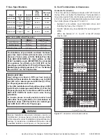
3-90-30007480
Hearth and Home Technolgies • Oxford Direct/Natural Vent Installation Manual_R3 • 02/19
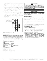
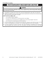
Roof Pitch
H (Min.) Ft.
Roof Pitch
H (Min.) Ft.
Flat to 6/12
1.0*
Over 11/12 to 12/12
4.0
Over 6/12 to 7/12
1.25*
Over 12/12 to 14/12
5.0
Over 7/12 to 8/12
1.5*
Over 14/12 to 16/12
6.0
Over 8/12 to 9/12
2.0*
Over 16/12 to 18/12
7.0
Over 9/12 to 10/12
2.5
Over 18/12 to 20/12
7.5
Over 10/12 to 11/12
3.25
Over 20/12 to 21/12
8.0
* 3 Feet. Minimum in Snow Regions
Horizontal
overhang
12
X
20 in.
(508 mm)
Lowest
Discharge
Opening
Termination
Cap
Roof Pitch
is X / 12
Vertical
wall
H (min.) - Minimum height
from roof to lowest
discharge opening.
24 in. min.
(610 mm)
Roof Pitch
H (Min.) Ft.
Roof Pitch
H (Min.) Ft.
Flat to 6/12
1.0*
Over 11/12 to 12/12
4.0
Over 6/12 to 7/12
1.25*
Over 12/12 to 14/12
5.0
Over 7/12 to 8/12
1.5*
Over 14/12 to 16/12
6.0
Over 8/12 to 9/12
2.0*
Over 16/12 to 18/12
7.0
Over 9/12 to 10/12
2.5
Over 18/12 to 20/12
7.5
Over 10/12 to 11/12 3.25
Over 20/12 to 21/12
8.0
* 3 ft. minimum in snow regions
Storm Collar
Roof
Flashing
Figure 3.18
- Minimum Height from Roof to Lowest Discharge
Opening
ST358
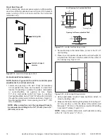
DW
Decorative
pipe around b-vent
5/15/03 djt
Decorative
7” Pipe
4” B-vent
Pipe
Draft Hood
Adapter
HHT Direct Vent
System may be used
from Draft Hood up
to the ceiling
Figure 3.19
- Decorative 7” pipe may be fitted around the B-vent
pipe.
The stove, when installed as a Natural vent heater, includes
a vent safety switch. Operating the stove when it is not
connected to a properly installed and maintained venting
system, or tampering with or disconnecting the vent safety
switch, can result in carbon monoxide (CO) poisoning and
possible death.
For U.S. installations:
The venting system must conform
with local codes and/or the current National Fuel Gas Code,
ANSI Z22.1.
For Canadian installations:
The venting system must
conform to the current CSA B149.1 installation code.
Install the Vent Pipe
Apply a bead of sealant around bottom end of inner starter
pipe (found in bag with logset) and attach to stove. Apply a
bead of sealant around top of inner starter pipe and install
the FSDHAGSLP Draft Hood according to Draft Hood
instructions, Figure 3.20.
Attach the first section of venting to the draft hood.
Depending on the length of the individual venting sections
and the lengths of the decorative pipe (if installed), you may
need to slip the decorative pipe over the venting sections
before attaching upper sections to lower ones. The sections
of decorative pipe should be oriented with their seams (if
any) toward the wall; sections usually do not need to be
fastened at each joint, other than slip sections. If the layout
includes a slip section, this should be the last section of
pipe visible in the room, at the ceiling. Complete the venting
according to the vent maker’s instructions.
Venting System Assembly - Natural Vent
General Information
The heater is shipped from the factory as a Direct Vent
Heater. It may be converted to a Natural Vent heater by
installing the Model FSDHAGSLP Draft Hood Adapter.
The heater is approved for installation as a Natural Vent.
Hearth & Home Technologies Direct Vent pipe could be
used directly after the Draft Hood Adapter up to the ceiling,
then B-vent pipe must be used. Do not mix types of B-vent
pipe; use components from one maker or the other. Follow
the vent component maker’s instructions exactly. The
heater will also accept standard or enameled 7” (150 mm)
diameter pipe, around the Type B venting, for decorative
purposes only, Figure 3.19.
NOTE: The restrictor plate supplied with the stove is
not used for Natural Vent applications.