


14
14
3-90-30007480
Hearth and Home Technolgies • Oxford Direct/Natural Vent Installation Manual_R3 • 02/19
B. Assembling the Stove:
Tools Required
•
Phillips screwdriver (stub)
•
Utility knife
•
Metal drill bit: size 28 (.140"/3.5mm)
•
Flat-blade screwdriver
• Power drill
•
Reciprocating saw
•
9/16" wrench
•
1/2” Wrench
Parts Bag Contents:
•
Three (3) Vent Screws
•
Wood handle w/insert lifter (handle for operable door)
•
Restrictor Plate
•
4" Starter pipe
•
Three (3) Phillips round-head bolts, 1/4"- 20 x 1/2"
•
One (1) Tube of Vent Gasket Cement
•
Four (4) CS, Hex Hd 3/8-16 x 1 Gr 2-Z
•
Four (4) Washer, Fl 3/8-Z
•
Propane Conversion Kit
•
Owner’s Installation and Operating Manual
Unpack Stove
Using the 1/2” wrench remove the (4) lag bolts installed
through the shipping brackets and into the skid. Once the lag
bolts are removed, remove the shipping brackets from around
each leg leveler located at each leg with the 7/16” Wrench.
WARNING
!
Only the IPI appliance is equipped with a three-prong
(grounded) plug for your protection against shock hazard
and should be plugged directly into a properly grounded
three-prong receptacle. Do not cut or remove the ground
-
ing prong from this plug.
C. Venting System Assembly
CAUTION
!
All HHT Direct Vent Stoves have been tested and
approved to ANSI/CSA Standards and will operate safely
when installed in accordance with this instruction manual.
Read all instructions before starting installation, then follow
these instructions carefully to maximize stove performance
and safety. Report damaged parts to your dealer.
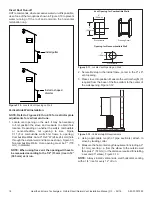
Important Safety Information
The termination cap MUST be vented directly to the outside.
The termination kit MUST NEVER be connected to a chimney
flue(s) servicing a separate solid-fuel burning appliance or
any other appliances.
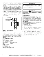
• Termination cap
MUST NOT
be recessed into a wall,
Figure 3.1.
• The installation must conform with local codes or in the
absence of local codes, with the National Fuel Gas Code,
ANSI Z223.1 (in the United States) or with the current
installation code CSA B149 (in Canada).
WARNING
!
Always maintain minimum clearances around vent
systems. Rear/Top Vent Vertical Side wall: Horizontal
sections of this vent system require a minimum of 3” (76
mm) clearances to combustibles at the top of the flue and
1” (25 mm) clearance at the sides and bottom until the flue
penetrates the outside wall. A minimum 1” clearance all
around the flue is acceptable at this point of penetration.
If vertical rise is 7-1/2 feet (2.3 m) or higher when top
venting, the clearance to combustibles is 1” on all sides of
the horizontal run. FOR VERTICAL RUNS ONLY, maintain
a 1” (25 mm) minimum clearance to all sides. Do not pack
the open air spaces around the stove or flue with insulation
or other materials. Any horizontal run must have a 1/4” rise
for every one (1) foot of run towards the vent termination.
Never run the vent level or down.
WARNING
!
Failure to follow these instructions may create a possible
fire hazard and will void the warranty.
WARNING
!
Any common venting of this gas appliance with other gas
appliances is not allowed.