59
NTT 240/460
Operation mode
Installation and user guide
Rev: 4.0
6.03.2.i
Resolver
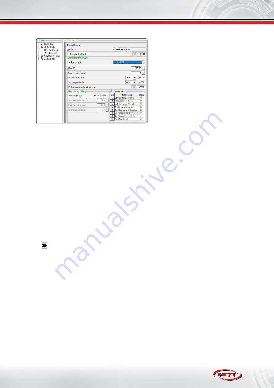
E’ necessario inserire correttamente:
•
Resolver pole pairs
•
Offset
Other parameters are:
•
Reverse Feedback
: feedback counter is reversed
related to motor rotation.
•
Resolver precision
: motor feedback ADC conversion
precision.
•
Encoder precision
: emulated encoder output
precision.
•
Reverse simulater encoder
: emulated encoder
counter direction is reversed related to motor
feedback counter.
•
Cogging compensation
: motor cogging mapping.
If resolver is used, it’s mandatory to correctly set resolver pole pairs. Then it’s mandatory to set correctly feedback
offset, set to 0° for all H.D.T. motors; otherwise, if third-party motor is used instead, please perform the autophasing
procedure
“6.07 Motor autophasing” pag. 82
Feedback resolution parameter allows to tune resolver precision between 10 and 16bit. Default value is set to
14bit and it allows to cover most applications with excellent behaviour; for application speed up to 5000RPM,
it’s possible to set 16bit resolution to increase positioning performance, but accepting a speed loop bandwidth
decreasing (at least 4 times lower than 14bit).
Encoder resolution parameter sets number of pulse per mechanical round (PPR), performed by emulated encoder
output with zero index. It’s possible to set only values equal to Feedback resolution or lower.
Besides, monitoring for resolver funcionality is visible.
Some visualized parameters are reserved.
Motor cogging map is available.
Connection is located into J5 connector (please see
“5.08 J5 connector: Feedback 1” pag. 36
1. supply excitation to resolver primary winding: EXC+ (pin 1) and EXC- (pin 2).
2. connect the sin/cos signals: COS- (pin 3), COS+ (pin 4), SEN- (pin 5), SEN+ (pin 10).
3. if available, connect motor temperature sensor PTC (pin 8-9).
!
NOTES:
•
If motor has not temperature PTC sensor, please short-circuit connector pins to bypass alarm provided
by drive.
•
If Hall sensors are managed, real shaft electric position related to HALL position sectors is displayed.
•
Hall sensor only does not provide good performance at low speeds. It has a good function starting from
10% of maximum speed, therefore, in the case of a 3000RPM motor, good performance are obtained
at more than 300RPM.
•
It’s possible to provide incremental channels to external controller via J7 connector in order to close
position loop externally.
•
For further information about motor cogging compensation, please see
.
Содержание NTT 240
Страница 129: ......


