background image

16

Z6AM

HBM

A1559-2.0 de/en/fr

Safety instructions

In cases where a breakage would cause injury to persons or damage to
equipment, the user must take appropriate safety measures (such as fall
protection, overload protection, etc.). For safe and trouble-free operation,
weighing modules must not only be correctly transported, stored, sited and
installed but must also be carefully operated and maintained.

It is essential to comply with the relevant accident prevention regulations. In
particular you should take into account the limit loads quoted in the specifica-
tions.

Use in accordance with the regulations

Z6AM type weighing modules are conceived  for weighing applications. Use
for any additional purpose shall be deemed to be not in accordance with the
regulations.

In the interests of safety, the weighing modules should only be operated as
described in the Mounting Instructions. It is also essential to observe the
appropriate legal and safety regulations for the application concerned during
use. The same applies to the use of accessories.

The weighing modules are not safety elements within the meaning of its use
as intended. Proper and safe operation of this transducer requires proper
transportation, correct storage, assembly and mounting and careful operation
and maintenance.

General dangers due to non-observance of the safety instructions

The Z6AM weighing modules correspond to the state of the art and are
fail-safe. The weighing modules can give rise to residual dangers if they are
inappropriately installed and operated by untrained personnel.

Everyone involved with the installation, commissioning, maintenance or repair
of a force transducer must have read and understood the Mounting
Instructions and in particular the technical safety instructions.

Residual dangers

The scope of supply and performance of the weighing modules covers only a
small area of weighing technology. In addition, equipment planners, installers
and operators should plan, implement and respond to the safety engineering
considerations of weighing technology in such a way as to minimise residual
dangers. Prevailing regulations must be complied with at all times. There must
be reference to the residual dangers connected with weighing technology.

Содержание Z6AM

Страница 1: ...A1559 2 0 de en fr W gemodule Weighing modules Modules de pesage Z6AM Montageanleitung Mounting instructions Notice de montage...

Страница 2: ...Deutsch Seite 3 14 English Page 15 26 Fran ais Page 27 38...

Страница 3: ...tage 8 4 Betrieb 9 5 Einbaubeispiele f r W gemodule mit Lenker 10 6 Elektrischer Anschluss 10 6 1 Parallelschaltung mehrerer W gemodule 11 6 2 Anschluss in Vierleiter Technik 11 6 3 Kabelverl ngerunge...

Страница 4: ...Sinngem gilt dies auch bei Verwendung von Zubeh r Die W gemodule sind keine Sicherheitselemente im Sinne des bestimmungs gem en Gebrauchs Der einwandfreie und sichere Betrieb des W gemodu les setzt sa...

Страница 5: ...timmungen nicht beachtet werden Sachschaden leichte oder mittlere K rperverletzung zur Folge haben k nnte Symbole f r Anwendungshinweise und n tzliche Informationen Symbol HINWEIS Weist darauf hin das...

Страница 6: ...sind nur von qualifiziertem Personal ausschlie lich ent sprechend der technischen Daten in Zusammenhang mit den nachstehend ausgef hrten Sicherheitsbestimmungen und Vorschriften einzusetzen Hierbei si...

Страница 7: ...arauf zu achten dass die vorgesehenen Montage Aufstellfl chen sauber eben und waagrecht ausgerichtet sind Etwaige Schiefstellungen k nnen je nach Einbausituation zum Beispiel durch entsprechende Keile...

Страница 8: ...en einer Speisespannung und den Vergleich der Ausgangsspannungen zu berpr fen Gr ere Ungleichm igkeiten sind zur Vermeidung von berlastun gen durch Einf gen von Unterlegblechen an den am geringsten be...

Страница 9: ...keit des Aufnehmers Faltenbalg beeintr chtigen Der Spalt des berlastanschlages und seitliche Anschl ge d rfen ebenfalls nicht verschmutzen Das Spiel des berlastanschlages siehe Angaben in Tabelle Tech...

Страница 10: ...werden 6 Elektrischer Anschluss Die W gezellen des W gemodules k nnen angeschlossen werden an Tr gerfrequenz Messverst rker oder Gleichspannungs Messverst rker die f r DMS Messsysteme geeignet sind D...

Страница 11: ...echnik Bei Anschluss an Verst rker mit Vierleiter Technik sind die Adern bl und gn sowie sw und gr miteinander zu verbinden Folgende Abweichungen treten bei ungek rztem Kabel 3 m auf Kennwert 0 2 und...

Страница 12: ...elle von Nennlast 150 R ckstellkraft bei 1mm seitlicher Verschiebung der auf gebrach ten Last 2 8 Max zul ssige seitliche Verschiebung quer zur Lenkerachse 1 mm 3 5 Max zul ssige Horizontalkraft in Le...

Страница 13: ...annung Uref V 5 Nennbereich der Versorgungsspan nung Bu V 0 5 12 Isolationswiderstand Ris G 5 Nennbereich der Umgebungs temperatur BT oC 10 40 Gebrauchstemperaturbereich Btu oC 30 70 Lagerungstemperat...

Страница 14: ...onen Ex Schutz Ausf hrung nach ATEX 95 Ex II 2 G EEx ia IIC T4 bzw T6 Zone 1 Ex II 3 G EEx nA II T6 Zone 2 Ex II 2 D IP68 T80 C 176 F Zone 21 EX II 3 D IP68 T80 C 176 F f r nichtleitenden Staub Zone 2...

Страница 15: ...21 5 Mounting examples for weigh modules with stay rods 22 6 Connection 22 6 1 Connecting several weighing modules in parallel 23 6 2 Connection using four wire circuitry 23 6 3 Cable extensions 23 7...

Страница 16: ...o the use of accessories The weighing modules are not safety elements within the meaning of its use as intended Proper and safe operation of this transducer requires proper transportation correct stor...

Страница 17: ...hich failure to comply with safety requirements could lead to damage to property slight or moderate physical injury Symbols indicating application notes and useful information Symbol NOTE Refers to th...

Страница 18: ...Qualified personnel These weighing modules are only to be installed by qualified personnel strictly in accordance with the technical data and with the safety rules and regulations which follow It is a...

Страница 19: ...taken to ensure that all surfaces for siting and mounting are clean smooth and level Depending on the mounting conditions any level ing error can be compensated for by using suitable wedges and compen...

Страница 20: ...voltage and comparing the output voltages To prevent overloads any large non uniformity should be compensated for by inserting shims under the supports that are least loa ded When tanks are heavy or...

Страница 21: ...way that movement of the transducer bellows is restricted The gap for the overload stop and lateral stops must also be kept free of contamination The play of the overload stop for details see table Sp...

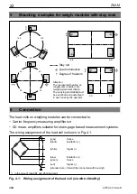
Страница 22: ...n each case by the operator 6 Connection The load cells on weighing modules can be connected to Carrier frequency measuring amplifiers or DC meas amplifiers suitable for strain gage based measurement...

Страница 23: ...ctions to amplifiers using four wire circuitry the cores bl blue and gn green should be connected together as should bk black and gr gray The following deviations occur in the case of cable of origina...

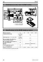
Страница 24: ...y kg 50 100 200 500 Limit load of load cell of maxi mum ca pacity 150 Restoring force for 1 mm side offset of ap plied load 2 8 Max permissible side offset trans verse to the stay rod axis1 mm 3 5 Max...

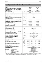
Страница 25: ...0 12 Reference voltage Uref V 5 Nominal range of excitation voltage Bu V 0 5 12 Insulation resistance Ris G 5 Nominal temperature range BT 10 40 14 104 Service temperature range Btu oC oF 30 70 22 15...

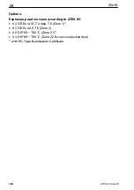
Страница 26: ...Options Explosion proof versions according to ATEX 95 II 2 G EEx ia IIC T4 resp T6 Zone 1 II 3 G EEx nA II T6 Zone 2 II 2 D IP68 T80 C Zone 21 II 3 D IP68 T80 C Zone 22 for non conductive dust with E...

Страница 27: ...ntage de modules de pesage de cuves avec barres de stabilisation 34 6 Raccordement 34 6 1 Mise en parall le de plusieurs mod de pesage de cuves 35 6 2 Raccordement en technique quatre conducteurs 35 6...

Страница 28: ...it de ce capteur celui ci doit tre utilis conform ment aux instructions de la notice de montage De plus il convient de respecter les r glements et consignes de s curit pour chaque utilisation particul...

Страница 29: ...e de montage les dangers r siduels sont signal s l aide des symboles suivants Des symboles qui indiquent des notices d application et des informations utiles Symbole ATTENTION Signification Situation...

Страница 30: ...rsonnel qualifi Ces modules de pesage appareil doit uniquement tre mis en place et manipul par du personnel qualifi et conform ment aux caract ristiques techniques et aux consignes de s curit d crites...

Страница 31: ...du montage Il faut s assurer que les surfaces d installation de montage pr vues sont propres planes et dispos es horizontalement Les ventuelles inclinaisons peuvent selon la situation d installation...

Страница 32: ...d alimentation et la comparaison des tensions de sortie Les in gali t s tr s importantes doivent tre compens es afin d viter les surcharges en ins rant des t les de calage au niveau des paliers les mo...

Страница 33: ...er la mobilit du capteur soufflet La fente de la but e de surcharge et les but es lat rales ne doivent galement pas s encrasser Le jeu de la but e de surcharge voir donn es du tableau Caract ristiques...

Страница 34: ...p rateur 6 Raccordement Les pesons du module de pesage de cuves peuvent tre raccord s des amplificateurs fr quence porteuse ou des amplificateurs tension continue convenant aux syst mes de mesure jaug...

Страница 35: ...s de raccordement des amplificateurs en technique quatre conduc teurs les fils bleu et vert ainsi que noir et gris doivent tre reli s Les carts suivants se produisent pour un c ble non raccourci 3 m s...

Страница 36: ...rge nominale kg 50 100 200 500 Charge limite du peson de la charge no minale 150 Force de rappel pour un d placement lat ral de 1 mm de la charge ap pliqu e 2 8 D placement lat ral maxi autoris perpen...

Страница 37: ...5 Plage nominale de la tension d alimen tation Bu V 0 5 12 R sistance d isolement Ris G 5 Plage nominale de la temp rature am biante BT oC 10 40 Plage de temp rature de service Btu oC 30 70 Plage de t...

Страница 38: ...ons Versions antid flagrants selon ATEX 95 Ex II 2 G EEx ia IIC T4 ou T6 Zone 1 Ex II 3 G EEx nA II T6 Zone 2 Ex II 2 D IP68 T80 C Zone 21 EX II 3 D IP68 T80 C pour poussi re non conductrice Zone 22 a...

Страница 39: ......

Страница 40: ...ee 45 D 64293 Darmstadt Tel 49 6151 803 0 Fax 49 6151 8039100 Email support hbm com Internet www hbm com nderungen vorbehalten Alle Angaben beschreiben unsere Produkte in allgemeiner Form Sie stellen...

Отзывы: