background image

Mounting Instructions | Montageanleitung |
Notice de montage

English

Deutsch

Français

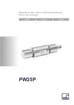
PW25P

Содержание PW25P Series

Страница 1: ...Mounting Instructions Montageanleitung Notice de montage English Deutsch Fran ais PW25P...

Страница 2: ...All product descriptions are for general information only They are not to be understood as a guarantee of quality or durability nderungen vorbehalten Alle Angaben beschreiben unsere Produkte in allgem...

Страница 3: ...Mounting Instructions Montageanleitung Notice de montage English Deutsch Fran ais PW25P...

Страница 4: ...ainst corrosion 8 3 2 Deposits 8 4 Mechanical installation 9 4 1 Important precautions during installation 9 4 2 Mounting 9 5 Electrical connection 11 5 1 Connection in a six wire configuration 11 5 2...

Страница 5: ...ntended for use as safety components Please also follow the instructions in the Additional safety precautions section Proper and safe operation of the load cells requires proper transportation correct...

Страница 6: ...t least the requirements of applicable safety and accident prevention regulations e g automatic emergency shutdown overload protection catch straps or chains or other fall protection The electronics c...

Страница 7: ...onsiderations of the weighing technology in such a way as to minimize residual dangers Pertinent national and local regulations must be complied with Conversions and modifications The transducer must...

Страница 8: ...nology is a requirement and as project personnel you must be familiar with these concepts 2 As automation plant operating personnel you have been instructed how to handle the machinery You are familia...

Страница 9: ...comply with safety requirements can lead to damage to property Important This marking draws your attention to important information about the product or about handling the product Tip This marking in...

Страница 10: ...gainst constant humidity and moisture 3 1 Protection against corrosion The load cell must be protected against chemicals that could attack the transducer body steel or the cable Notice Acids and all s...

Страница 11: ...transducer cannot be overloaded WARNING There is a danger of the transducer breaking if it is overloaded This can cause danger for the operating personnel of the system in which the transducer is ins...

Страница 12: ...ith regard to screw dimensions min 4 min 4 Installation 2 x M6 tightening torque 10 Nm max thread reach 10 mm Platform Mounting base Intermediate plate customer construction Intermediate plate custome...

Страница 13: ...signal 2 3 4 5 6 7 1 8 Plug in contact 2 not in use Plug in contact 4 not in use Fig 5 1 Connector pin assignment With this connector pin assignment the output voltage at the measuring amplifier is po...

Страница 14: ...in a four wire configuration where the cable percentage must be added 5 3 Shortening the cable If the transducer is connected to an amplifier in a six wire configuration the transducer cable can be sh...

Страница 15: ...g circuit Therefore S Use shielded low capacitance measurement cables only HBM cables fulfill both conditions S Do not route the measurement cables parallel to power lines and control circuits If this...

Страница 16: ...er product information can be found at www hbm com pw 7 Dimensions Dimensions in mm 1 mm 0 03937 inches 1 KAB168 D 14 5 L 62 1 KAB175 D 16 L 62 6 19 0 1 M6 100 0 2 19 0 1 M6 10 10 35 68 35 15 5 25 5 M...

Страница 17: ...e with M12 F connector 8 pin stainless steel IP68 IP69K hygiene design 3 m long 1 KAB175 3 1 Connection cable with M12 F connector 8 pin stainless steel IP68 IP69K hygiene design 6 m long 1 KAB175 6 1...

Страница 18: ...16 A03627_02_Y00_01 HBM public PW25P Pin assignment 1 KAB175 Color code Connection White Measurement signal Red Measurement signal Blue Excitation voltage Black Excitation voltage Green Sense lead Gra...

Страница 19: ...Mounting Instructions Montageanleitung Notice de montage English Deutsch Fran ais PW25P...

Страница 20: ...Bedingungen am Einbauort 8 3 1 Korrosionsschutz 8 3 2 Ablagerungen 8 4 Mechanischer Einbau 9 4 1 Wichtige Vorkehrungen beim Einbau 9 4 2 Montage 9 5 Elektrischer Anschluss 11 5 1 Anschluss in Sechslei...

Страница 21: ...llen sind nicht zum Einsatz als Sicherheitsbauteile bestimmt Bitte beachten Sie hierzu den Abschnitt Zus tzliche Sicherheitsvorkehrungen Der einwandfreie und sichere Betrieb der W gezellen setzt sachg...

Страница 22: ...hlfunktion der W gezellen Menschen oder Sachen zu Schaden kommen k nnen m ssen vom Anwender geeignete zus tzliche Sicherheitsvorkehrungen getroffen werden die zumindest den Anforderungen der einschl g...

Страница 23: ...e oder durch diese berwachte Lasten Menschen oder Sachen zu Schaden kommen k nnen Der Leistungs und Lieferumfang des Aufnehmers deckt nur einen Teilbereich der W getechnik ab da Messungen mit resistiv...

Страница 24: ...ber die ihrer T tigkeit entsprechende Qualifikationen verf gen Dazu z hlen Personen die mindestens eine der drei folgenden Voraus setzungen erf llen 1 Ihnen sind die Sicherheitskonzepte der Automatisi...

Страница 25: ...gen nicht beachtet werden Sachsch den zur Folge haben kann Wichtig Diese Kennzeichnung weist auf wichtige Informa tionen zum Produkt oder zur Handhabung des Pro duktes hin Tipp Diese Kennzeichnung wei...

Страница 26: ...e Feuchteeinwirkung gesch tzt werden 3 1 Korrosionsschutz Die W gezelle muss gegen Chemikalien gesch tzt werden die den Stahl des Aufnehmerk rpers oder das Kabel angreifen Hinweis S uren und alle Stof...

Страница 27: ...erlastung des Aufnehmers besteht die Gefahr dass der Auf nehmer bricht Dadurch k nnen Gefahren f r das Bedienpersonal der Anlage auftreten in die der Aufnehmer eingebaut ist Treffen Sie geeignete Sich...

Страница 28: ...sprechenden Informationen der Schraubenhersteller min 4 min 4 Montage 2x M6 Anzugsmoment 10 Nm max Einschraub tiefe 10 mm Plattform Basisplatte Zwischenplatte Konstruktion durch Kunden Zwischenplatte...

Страница 29: ...ckkontakt 2 nicht belegt Steckkontakt 4 nicht belegt Abb 5 1 Steckerbelegung Bei dieser Steckerbelegung ist bei Belastung des Aufnehmers siehe Abb 4 1 die Ausgangsspannung am Messverst rker positiv Di...

Страница 30: ...el und Aufnehmer hier kommt der Anteil des Kabels hinzu 5 3 Kabelk rzung Bei einem Anschluss des Aufnehmers an Verst rker in Sechsleiter Technik k nnen Sie das Kabel des Aufnehmers bei Bedarf k rzen o...

Страница 31: ...esskreis Deshalb S Verwenden Sie nur abgeschirmte kapazit tsarme Messkabel HBM Kabel erf llen diese Bedingungen S Legen Sie die Messkabel nicht parallel zu Starkstrom und Steuerleitungen Falls das nic...

Страница 32: ...mation Weitere Produktinformationen unter www hbm com de pw 7 Abmessungen Abmessungenin mm 1 KAB168 D 14 5 L 62 1 KAB175 D 16 L 62 6 19 0 1 M6 100 0 2 19 0 1 M6 10 10 35 68 35 15 5 25 5 M12 16 150 0 2...

Страница 33: ...kabel mit Stecker M12 F 8 polig Edelstahl IP68 IP69K Hygieneausf hrung 3 m lang 1 KAB175 3 1 Anschlusskabel mit Stecker M12 F 8 polig Edelstahl IP68 IP69K Hygieneausf hrung 6 m lang 1 KAB175 6 1 Techn...

Страница 34: ...ubeh r 16 A03627_02_Y00_01 HBM public PW25P Anschlussbelegung 1 KAB175 Aderfarbe Anschluss Wei Messsignal Rot Messsignal Blau Speisespannung Schwarz Speisespannung Gr n F hlerleitung Grau F hlerleitun...

Страница 35: ...Mounting Instructions Montageanleitung Notice de montage English Deutsch Fran ais PW25P...

Страница 36: ...1 Protection contre la corrosion 8 3 2 D p ts 8 4 Montage m canique 9 4 1 Pr cautions importantes lors du montage 9 4 2 Montage 9 5 Raccordement lectrique 11 5 1 Raccordement en technique six fils 11...

Страница 37: ...omme l ments de s curit Reportez vous ce sujet au paragraphe Mesures de s curit suppl mentaires Afin de garantir un fonctionnement parfait et en toute s curit des pesons il convient de veiller un tran...

Страница 38: ...nstallateur et l exploitant de l installation Lorsque les pesons risquent de blesser des personnes ou endommager des biens suite une rupture ou un dysfonctionnement l utilisateur doit prendre des mesu...

Страница 39: ...onnements des pesons pouvant leur tour provoquer des pr judices corporels ou mat riels de par les charges agissant sur les pesons ou celles surveill es par ces derniers Les performances du capteur et...

Страница 40: ...du produit et disposant des qualifications n cessaires l accomplissement de leur t che En font partie les personnes remplissant au moins une des trois conditions suivantes 4 Vous connaissez les conce...

Страница 41: ...qui si les dispositions relatives la s curit ne sont pas respect es peut avoir pour cons quence des d g ts mat riels Important Ce marquage signale que des informations importantes concernant le produ...

Страница 42: ...manente d humidit 3 1 Protection contre la corrosion Le peson doit tre prot g contre les produits chimiques susceptibles d attaquer l acier du corps du capteur ou le c ble Note Les acides et toutes le...

Страница 43: ...de surcharge du capteur ce dernier risque de se briser Cela peut tre dangereux pour les op rateurs de l installation dans laquelle le capteur est mont Prendre des mesures de protection appropri es pou...

Страница 44: ...ntes fournies par le fabricant des vis min 4 min 4 Montage 2x M6 Couple de serrage 10 Nm Longueur de filet maxi 10 mm Plate forme Plaque de fondation Plaque interm diaire construction par le client Pl...

Страница 45: ...8 signal de mesure 2 3 4 5 6 7 1 8 Contact 2 libre Contact 4 libre Fig 5 1 Affectation des p les du connecteur Avec cette affectation des p les du connecteur la tension de sortie de l amplificateur d...

Страница 46: ...naison c ble capteur Dans ce cadre la partie du c ble doit tre ajout e cela 5 3 Raccourcissement de c ble Lors d un raccordement du capteur l amplificateur en technique six fils le c ble du capteur pe...

Страница 47: ...quoi il faut S utiliser uniquement des c bles de mesure blind s de faible capacit les c bles HBM satisfont ces conditions S absolument viter de poser les c bles de mesure en parall le avec des lignes...

Страница 48: ...iques Information Pour plus d informations sur les produits voir www hbm com fr pw 7 Dimensions Dimensions en mm 1 KAB168 D 14 5 L 62 1 KAB175 D 16 L 62 6 19 0 1 M6 100 0 2 19 0 1 M6 10 10 35 68 35 15...

Страница 49: ...IP68 IP69K version hygi nique 3 m de long 1 KAB175 3 1 C ble de liaison avec connecteur M12 F 8 p les acier inoxydable IP68 IP69K version hygi nique 6 m de long 1 KAB175 6 1 Pour les caract ristiques...

Страница 50: ...HBM public PW25P Code de raccordement 1 KAB175 Couleur du fil Raccordement Blanc Signal de mesure Rouge Signal de mesure Bleu Tension d alimentation Noir Tension d alimentation Vert Fil de contre r ac...

Страница 51: ...Accessoires PW25P A03627_02_Y00_01 HBM public 17...

Страница 52: ...www hbm com HBM Test and Measurement Tel 49 6151 803 0 Fax 49 6151 803 9100 info hbm com measure and predict with confidence A03627_02_Y00_01 7 0101 0006 HBM public...

Отзывы: