11
M408, M416
HBM
A2400-1.1 en/de
2
Device connections
3
4
1
2
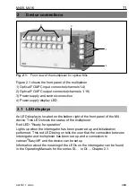
Fig. 2.1:
Front view of the multiplexer for optical SGs
Figure 2.1 shows the front panel of the multiplexer
1) Optical FC/APC input connector(channels 1-4)
2) Optical FC/APC output connector(channels 1-16)
3) Power supply and control connection
4) Power supply display LED.
2.1
LED displays
An LED display is located on the bottom right of the front panel of the M4
…
device. This LED shows the status of the multiplexer.
Red LED: ”Ready for operation”
Lights up when the interrogator has been powered up and initialization
performed. This red LED being on tells the user that the connection between
interrogator and multiplexer has been set up and a connection to
catman
Easy/AP and the device can be set up.
Information about the meaning of the LEDs on the interrogator can be found
in the Operating Manuals for the series SI-
…
or DI-... Chapter 2.1.
Содержание M408
Страница 2: ......
Страница 15: ...15 M408 M416 HBM A2400 1 1 en de Fig 3 1 Connection diagram of a multiplexer with a 4 channel DI interrogator...
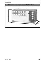
Страница 21: ...21 M408 M416 HBM A2400 1 1 en de 7 Dimensions in mm 1 mm 0 03937 inches 234 123 114...
Страница 22: ...22 M408 M416 HBM A2400 1 1 en de...
Страница 35: ...35 M408 M416 HBM A2400 1 1 en de Abb 3 1 Anschlussschema eines Multiplexers mit einem 4 Kanal DI Interrogator...
Страница 41: ...41 M408 M416 HBM A2400 1 1 en de 7 Abmessungen 234 123 114...
Страница 42: ...42 M408 M416 HBM A2400 1 1 en de...
Страница 43: ...43 M408 M416 HBM A2400 1 1 en de...


