background image

Page 8

FAA Approved 

Original Issue: Feb 28, 2006

Sub-section - 5.50

LANDING FIELD LENGTHS

Hawker 850XP Pro Line 21 Airplane Flight Manual

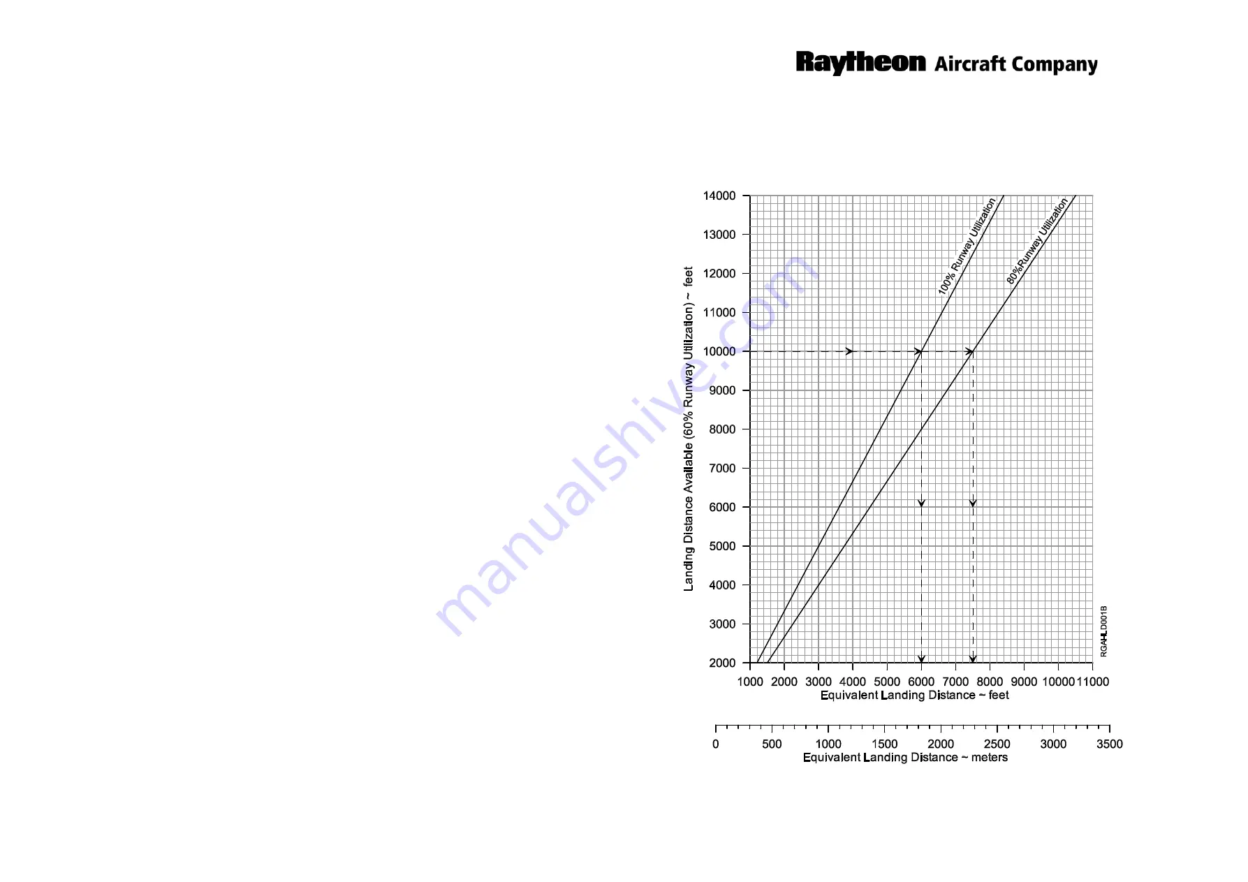
Figure 5.50.2

OPERATIONAL FACTOR ADJUSTMENTS

FOR

LANDING DISTANCE

For Training Purposes Only

Содержание Hawker 850XP

Страница 1: ...it 140 1702 is Installed and Serials 258789 thru 258794 258796 thru 258801 258803 and After FAA Approved Airplane Flight Manual AIRPLANES EQUIPPED WITH COLLINS PRO LINE 21 AVIONICS Airplane Serial Number Airplane Registration Number Copyright 2007 Hawker Beechcraft Corporation All rights reserved For Training Purposes Only ...

Страница 2: ...ed any longer with Raytheon Company Any Raytheon marks contained in this document are owned by Raytheon Company and are employed pursuant to a limited license granted by Raytheon Company The export of these commodities technology or software are subject to the US Export Administration Regulations Diversion contrary to US law is prohibited For guidance on export control requirements contact the Com...

Страница 3: ...sue Feb 28 2006 3 Original Issue Feb 28 2006 4 Original Issue Feb 28 2006 5 Original Issue Feb 28 2006 6 Original Issue Feb 28 2006 7 Original Issue Feb 28 2006 8 Original Issue Feb 28 2006 9 Original Issue Feb 28 2006 10 Original Issue Feb 28 2006 Section Page Revision Date 11 Original Issue Feb 28 2006 12 Original Issue Feb 28 2006 13 Original Issue Feb 28 2006 14 Original Issue Feb 28 2006 15 O...

Страница 4: ... 2006 13 Original Issue Feb 28 2006 14 Original Issue Feb 28 2006 15 Original Issue Feb 28 2006 16 Original Issue Feb 28 2006 17 Original Issue Feb 28 2006 Section Page Revision Date 18 Original Issue Feb 28 2006 19 Revision A1 Mar 6 2007 20 Revision A1 Mar 6 2007 21 Revision A1 Mar 6 2007 22 Original Issue Feb 28 2006 23 Original Issue Feb 28 2006 24 Original Issue Feb 28 2006 25 Original Issue F...

Страница 5: ... 28 2006 37 Original Issue Feb 28 2006 38 Original Issue Feb 28 2006 39 Original Issue Feb 28 2006 40 Original Issue Feb 28 2006 41 Original Issue Feb 28 2006 42 Original Issue Feb 28 2006 Section Page Revision Date 43 Original Issue Feb 28 2006 44 Original Issue Feb 28 2006 45 Original Issue Feb 28 2006 46 Original Issue Feb 28 2006 47 Original Issue Feb 28 2006 48 Original Issue Feb 28 2006 49 O...

Страница 6: ... 2006 24 Original Issue Feb 28 2006 25 Original Issue Feb 28 2006 26 Original Issue Feb 28 2006 27 Original Issue Feb 28 2006 Section Page Revision Date 28 Original Issue Feb 28 2006 29 Original Issue Feb 28 2006 30 Original Issue Feb 28 2006 31 Original Issue Feb 28 2006 32 Original Issue Feb 28 2006 33 Original Issue Feb 28 2006 34 Original Issue Feb 28 2006 35 Original Issue Feb 28 2006 Sub sec...

Страница 7: ... Original Issue Feb 28 2006 36 Original Issue Feb 28 2006 37 Original Issue Feb 28 2006 38 Original Issue Feb 28 2006 39 Original Issue Feb 28 2006 Section Page Revision Date 40 Original Issue Feb 28 2006 41 Original Issue Feb 28 2006 42 Original Issue Feb 28 2006 Sub section 5 25 NET TAKE OFF FLIGHT PATH APR ON 1 Original Issue Feb 28 2006 2 Original Issue Feb 28 2006 3 Original Issue Feb 28 2006...

Страница 8: ... Original Issue Feb 28 2006 7 Original Issue Feb 28 2006 8 Original Issue Feb 28 2006 9 Original Issue Feb 28 2006 10 Original Issue Feb 28 2006 11 Original Issue Feb 28 2006 12 Original Issue Feb 28 2006 Section Page Revision Date 13 Original Issue Feb 28 2006 14 Original Issue Feb 28 2006 15 Original Issue Feb 28 2006 16 Original Issue Feb 28 2006 17 Original Issue Feb 28 2006 18 Original Issue ...

Страница 9: ...ight Manual LIST OF EFFECTIVE PAGES continued Section Page Revision Date Part 2 1 Revision A3 Apr 26 2007 2 Revision A3 Apr 26 2007 Section 7 SUPPLEMENTS 1 Original Issue Feb 28 2006 2 Original Issue Feb 28 2006 See LOG OF SUPPLEMENTS For Training Purposes Only ...

Страница 10: ...ORMANCE Pages 4 8 and 12 Jun 2 2009 140 590035 0005TC3 Information for transferring 800XP STC supplements into the 850XP Airplane Flight Manual Only applicable to airplanes with kit 140 1702 Section 7 SUPPLEMENTS Page 1 Jun 30 2006 140 590035 0005TC4 Issue 2 Revised the P RNAV equipment list to include DBU 5000 Section 2 LIMITATIONS Page 21 May 1 2008 NOTE Temporary Changes TC5 and TC6 not issued ...

Страница 11: ...orary Changes dated prior to the Issue Date near the top of Page 1 of 2 Part Number Subject Date NOTE Temporary Changes TC9 TC10 and TC11 not issued 140 590035 0005TC12 Revised text with additional information and procedures for AIRFRAME ICE PROTECTION SYSTEM MALFUNCTIONS Sub section 4 05 ABNORMAL PROCEDURES Page 39 Dec 23 2010 140 590035 0005TC13 Additional procedures for THREE GREENS NOT INDICAT...

Страница 12: ...ru 21 Updated the page header to reflect the new company name Page 9 Added step to AFTER TAKE OFF CHECKS to Set Climb Power Section 6 WEIGHT BALANCE Part 1 Pages 1 thru 22 Updated the page header to reflect the new company name Page 1 Revised the Table of Contents Page 2 Added note regarding Non FAA approved pages Page 19 Corrected the figure number references Page 21 Corrected the figure numbers ...

Страница 13: ...Page 2 of 2 Airplane Flight Manual LOG OF REVISIONS continued Section Page Description A3 For Training Purposes Only ...

Страница 14: ...nged the copyright statement to reflect Hawker Beechcraft Corporation Revised the header on the logo page to reflect Hawker Beechcraft Corporation Added the Hawker Beechcraft Inc owner statement to logo page List of Effective Pages Pages 1 thru 7 Revised page header to reflect Hawker Beechcraft Corporation and updated for Revision A2 Log of Revisions Pages 1 of 1 Revised page header to reflect Haw...

Страница 15: ...sed the Loading and Flight Envelope Kilograms Meters chart Section 3 EMERGENCY PROCEDURES Page 19 Removed requirement to Don Smoke Goggles from the memory box goggles are built into the oxygen mask Page 20 Removed requirement to Don Smoke Goggles from the memory box Page 21 Removed requirement to Don Smoke Goggles from the memory box Section 6 WEIGHT BALANCE Page 4 Revised the definition for Minim...

Страница 16: ...Flight Manual LOG OF REVISIONS FAA Approved Airplane Flight Manual P N 140 590035 0005 Original Issue February 28 2006 Section Page Description All Sections and Pages Original Issue Refer to the LIST OF EFFECTIVE PAGES A For Training Purposes Only ...

Страница 17: ...DURES 9 SECTION 4 ABNORMAL NORMAL PROCEDURES 11 Sub section 4 05 ABNORMAL PROCEDURES 11 Sub section 4 10 NORMAL PROCEDURES 11 SECTION 5 PERFORMANCE 11 SECTION 6 WEIGHT BALANCE 12 SECTION 7 SUPPLEMENTS 12 ABBREVIATIONS and ACRONYMS 13 DEFINITIONS 17 IAS 17 CAS 17 EAS 17 TAS 17 Indicated Mach Number IMN 17 Pressure Altitude 17 Indicated Outside Air Temperature IOAT 17 Air Temperature 17 Weight 17 In...

Страница 18: ...Page 2 FAA Approved Original Issue Feb 28 2006 Section 1 GENERAL Hawker 850XP Pro Line 21 Airplane Flight Manual Intentionally left blank For Training Purposes Only ...

Страница 19: ...amiliar with the operation of the airplane Suggestions and recommendations have been made within it to aid in obtaining maximum performance without sacrificing economy Be familiar with and operate the airplane in accordance with the FAA approved Airplane Flight Manual and or placards which are located in the airplane This manual includes the material required to be furnished to the pilot by the Fe...

Страница 20: ...S THE SERVICE HISTORY OF WHICH IS UNKNOWN OR CANNOT BE AUTHENTICATED MAY HAVE BEEN SUBJECTED TO UNACCEPTABLE STRESSES OR TEMPERATURES OR HAVE OTHER HIDDEN DAMAGE NOT DISCERNIBLE THROUGH ROUTINE VISUAL OR USUAL NON DESTRUCTIVE TESTING TECHNIQUES THIS MAY RENDER THE PART COMPONENT OR STRUCTURAL ASSEMBLY EVEN THOUGH ORIGINALLY MANUFACTURED BY RAYTHEON AIRCRAFT UNSUITABLE AND UNSAFE FOR AIRPLANE USE R...

Страница 21: ...S page is provided and is to be filed in front of the manual immediately following the LOG OF TEMPORARY CHANGES All LOG OF REVISIONS pages must be retained until the manual is reissued A capital letter in the lower right corner of the LOG OF REVISIONS page designates the Original Issue A or reissue B C etc covered by the LOG OF REVISIONS page If a number follows the letter it designates the sequen...

Страница 22: ...w to obtain Revision Service applicable to this manual or other Raytheon Aircraft Service Publications refer to the latest revision of Raytheon Aircraft Service Bulletin SB 00 2001 or visit the web site at http www raytheonaircraft com service_support publications asp Raytheon Aircraft Company expressly reserves the right to supersede cancel and or declare obsolete without prior notice any part pa...

Страница 23: ...vised a new LOG page will replace the previous one since it contains a listing of all previous approvals plus the new approval The supplemental material will be added to the section in accordance with the sequence specified on the LOG page NOTE Upon receipt of a new or revised supplement compare the existing LOG page in the manual with the corresponding applicable LOG page accompanying the new or ...

Страница 24: ...Page 8 FAA Approved Original Issue Feb 28 2006 Section 1 GENERAL Hawker 850XP Pro Line 21 Airplane Flight Manual Intentionally left blank For Training Purposes Only ...

Страница 25: ... to some other category and to a particular use SECTION 3 EMERGENCY PROCEDURES The emergency procedures contained in this section have been developed and recommended by the manufacturer for use in the operation of this airplane Emergency conditions may occur when different combinations of events are encountered Some emergency conditions may require use of multiple procedures depending on the situa...

Страница 26: ...le of the page The MWS panel also provides repeater annunciators which have an upward pointing arrow When illuminated these annunciators indicate to the flight crew that an additional warning annunciator has illuminated on the overhead roof panel An illustration of the red Master Warning System lamps on the glareshield is not provided It is expected that the flight crew are familiar with the need ...

Страница 27: ...e in the operation of this airplane These procedures are for guidance only in identifying acceptable normal operating procedures and are not to be considered mandatory or in any way construed to prohibit an operator from developing equivalent FAA approved procedures SECTION 5 PERFORMANCE The performance information provided in this section relates to a Hawker 850XP airplane equipped with Collins P...

Страница 28: ...center of gravity limitations The Basic Empty Weight and Balance As Licensed and Equipment List are not FAA Approved SECTION 7 SUPPLEMENTS When items or systems have been installed in the airplane and not included in the main sections of this Airplane Flight Manual this section will contain the FAA approved supplemental data required for safe operation of this airplane Each supplement TC or STC wi...

Страница 29: ...ck AP Autopilot APPR Approach APR Automatic Performance Reserve APR ON APR system must be serviceable and armed for takeoff APU Auxiliary Power Unit ARTE Above Runway Threshold Elevation ASDA Accelerate Stop Distance Available ASEL Altitude Select ASI Air Speed Indicator ASIR Air Speed Indicator Reading ATC Air Traffic Control ATT Attitude AUX Auxiliary BITE Built In Test Equipment BRK Brake BUS T...

Страница 30: ... Aviation Organization IFR Instrument Flight Rules ILS Instrument Landing System IMN Indicated Mach Number INV Inverter IOAT Indicated Outside Air Temperature in Hg Inches of Mercury ISA International Standard Atmosphere ITT Interstage Turbine Temperature kg Kilogram s KIAS Knots Indicated Airspeed kPa Kilo Pascals kph Kilometers Per Hour kt Knot s lb Pound s lb in2 Pounds Per Square Inch LDA Loca...

Страница 31: ...ric Pressure in Millibars at Airfield Height QNH Barometric Pressure in Millibars at Sea Level RA Radio Altimeter or Resolution Advisory RAIM Receiver Autonomous Integrity Monitoring REV Reversionary RNAV Area Navigation RPM or rpm Revolutions Per Minute RVR Runway Visual Range RVSM Reduced Vertical Separation Minimum SDF Simplified Directional Facility SFD Secondary Flight Display SL Sea Level SM...

Страница 32: ...itions refer to Sub section 5 10 VA Design Maneuvering Speed VAPP Approach Speed VFE VFO Maximum Flap Extended Flap Operation Speed VLE Maximum Landing Gear Extended Speed VLO Maximum Landing Gear Operating Speed VMC Minimum Control Speed VMO MMO Maximum Operating Limit Speed Mach Operating Speed VRA Rough Air Speed WAT Weight Altitude Air Temperature WS Windshear XDATA Cross side data XE Power Em...

Страница 33: ...elative air density for the altitude Indicated Mach Number IMN The reading obtained on a Machmeter having no calibration error If the calibration error of the particular instrument is not known the actual reading may be taken to be equal to the Indicated Mach number because the tolerances permitted on the instrument are small Pressure Altitude An atmospheric pressure expressed as the altitude whic...

Страница 34: ...ts Where a volumetric quantity is used it is stated to be US gallons or liters Fuel quantities are given by weight in units of pounds and kilograms Obstacle Clearance Altitude Height OCA H The lowest altitude OCA or alternatively the lowest height above the elevation of the relevant runway threshold or above the airfield elevation as applicable OCH used in establishing compliance with appropriate ...

Страница 35: ...er 850XP Pro Line 21 Airplane Flight Manual M9409_0 AI 51 FT 1 64 IN 15 59 M OVERALL LENGTH 54 FT 4 IN 16 55M 9 FT 2 IN 2 79M TRACK 21 FT 0 5IN 6 41M WHEELBASE 20 FT 6 10M TAIL SPAN 17 FT 5 IN 5 31 M OVERALL HEIGHT GENERAL DIMENSIONS Figure 1 1 For Training Purposes Only ...

Страница 36: ...ING LIMITATIONS 7 LOAD LIMITATIONS 7 Center of Gravity Limitations 7 Figure 2 1 LOADING and FLIGHT ENVELOPE POUNDS FEET 8 Figure 2 2 LOADING and FLIGHT ENVELOPE KILOGRAMS METERS 9 ICE PROTECTION LIMITATIONS 11 Icing General 11 Airframe Icing 11 Wing Tail Antice System 11 Engine Icing 11 SEVERE ICING CONDITIONS LIMITATIONS 12 ENGINE LIMITATIONS 13 Engine Type 13 Engine Limitations 13 Approved Engin...

Страница 37: ...ns 18 Main Engine Starter Duty Cycle 18 Operation of Electrical Circuit Breakers 18 AVIONICS LIMITATIONS 19 General 19 HF Radio 19 Electronic Standby Instrument System ESIS 19 Flight Management System 19 Autopilot 21 VNAV 22 EGPWS 23 TCAS II 23 Mode S Enhanced Surveillance Transponder 24 AIRSPEED LIMITATIONS 25 Maximum Operating Speed 25 Maximum Operating Mach Number 25 Maneuvering Speed 25 Wing F...

Страница 38: ...ng Exit 27 Cabin High Datum 27 Crew Seats 27 Ditching 27 Inter compartment Door 27 Lift Dump 27 Maneuvering Load Factor Limitations 27 Minimum Flight Crew 27 Nosewheel Tires 27 Number of Occupants 27 Pressure Cabin 27 Rudder Bias 28 Smoking 28 System Gage Markings 28 Weather Radar 28 Wheel Brakes 28 Table 1 Take off Weights for Wheel Brakes Waiting Periods 29 For Training Purposes Only ...

Страница 39: ...Page 4 Section 2 LIMITATIONS FAA Approved Original Issue Feb 28 2006 Hawker 850XP Pro Line 21 Airplane Flight Manual Intentionally left blank For Training Purposes Only ...

Страница 40: ... 23 350 lb 10 591 kg Minimum Operating Weight 16 100 lb 7303 kg Maximum Zero Fuel Weight 18 450 lb 8369 kg Minimum Zero Fuel Weight 14 120 lb 6405 kg PERFORMANCE LIMITATIONS Take off Weight Maximum Take off Weight is limited by the most restrictive of the following 28 000 lb 12 701 kg As shown on the MAXIMUM TAKE OFF WEIGHT FOR ALTITUDE AND TEMPERATURE graphs see Sub section 5 15 The maximum permi...

Страница 41: ...published elevation shall be used when the field pressure altitude is below the lowest published elevation Maximum Permissible Altitude Maximum permissible operating altitude is 41 000 ft Maximum permissible altitude with flaps lowered or landing gear extended is 20 000 ft Air Temperature Maximum All Flight Regimes ISA 35 C Ground prior to engine start Flight compartment exposed to direct sunlight...

Страница 42: ...BALANCE of this Airplane Flight Manual and as provided on placards in the Baggage Stowage Compartments LOAD LIMITATIONS Center Of Gravity Limitations The center of gravity must always lie between the forward and aft limits as defined in the envelope shown in Figures 2 1 and 2 2 The limits apply with the landing gear up The effect of the landing gear in the down position is negligible The center of...

Страница 43: ...FROM C G DATUM FEET POSITIVE AFT AIRCRAFT WEIGHT POUNDS 14 15 16 17 18 19 20 21 22 23 24 25 26 27 28 29 30 31 32 33 34 35 36 37 PERCENT STANDARD MEAN CHORD SMC ZONE A USABLE ONLY WITH VENTRAL TANK FUEL MAXIMUM TAKE OFF WEIGHT 28 000 lb MAXIMUM RAMP WEIGHT 28 120 lb MAXIMUM LANDING WEIGHT 23 350 lb MAXIMUM ZERO FUEL WEIGHT 18 450 lb MINIMUM ZERO FUEL WEIGHT 14 120 lb MINIMUM OPERATING WEIGHT 16 100...

Страница 44: ...06 0 03 0 00 0 03 0 06 0 09 0 12 0 15 0 18 0 21 0 24 0 27 0 30 0 33 0 36 0 39 0 42 DISTANCE FROM C G DATUM METERS POSITIVE AFT AIRCRAFT WEIGHT KILOGRAMS 14 15 16 17 18 19 20 21 22 23 24 25 26 27 28 29 30 31 32 33 34 35 36 37 PERCENT STANDARD MEAN CHORD SMC ZONE A USABLE ONLY WITH VENTRAL TANK FUEL MAXIMUM TAKE OFF WEIGHT 12 701 kg MAXIMUM LANDING WEIGHT 10 591 kg MAXIMUM RAMP WEIGHT 12 755 kg MAXI...

Страница 45: ...Page 10 Section 2 LIMITATIONS FAA Approved Original Issue Feb 28 2006 Hawker 850XP Pro Line 21 Airplane Flight Manual Intentionally left blank For Training Purposes Only ...

Страница 46: ...h on Page 11 Icing conditions exist on the ground during takeoff and in flight when Static Air Temperature SAT is 10 C or below and visible moisture in any form is present e g clouds fog with visibility of 1 mile 1600 meters or less rain snow sleet and ice crystals Insert this Temporary Change Page 1 of 1 into the Hawker 850XP FAA Approved Airplane Flight Manual to face Page 11 in Section 2 LIMITA...

Страница 47: ...imited take off weight must be reduced by 1000 lb 454 kg and the net flight path reference and fourth segment climb gradients must be obtained using a weight 1000 lb 454 kg higher than the actual weight Frost is allowable on the fuselage provided the layer is thin enough to distinguish the surface features such as paint lines or markings underneath but all vents probes and ports must be clear of f...

Страница 48: ... AND CONTROLLABILITY OF THE AIRPLANE During flight severe icing conditions that exceed those for which the airplane is certificated shall be determined by the following visual cues If one or more of these visual cues exists immediately request priority handling from Air Traffic Control to facilitate a route or an altitude change to exit the icing conditions Extensive ice accumulation on the airfra...

Страница 49: ...PR operation must be recorded in the technical log 2 This is not a normal cruise setting CONDITION RPM MAX ITT C TIME LIMIT N1 N2 Start or Relight 978 996 over 996 Unrestricted 10 Seconds 5 Seconds Takeoff 100 100 8 978 1006 1016 5 Minutes 5 Seconds 2 Seconds Maximum Take off Thrust APR Operating see NOTE 1 100 100 8 996 1006 1016 5 Minutes 5 Seconds 2 Seconds Initial Maximum Take off Thrust APR N...

Страница 50: ...d Engine Instrument Markings Red Indications A maximum or minimum limit has been exceeded Yellow Indications Cautionary operations permissible for short duration or in special circumstances refer to individual limitations Green or White Indications Normal operations Airplanes which have not accomplished Honeywell Service Bulletin 72 3597 or 72 3662 Airplanes which have accomplished Honeywell Servi...

Страница 51: ...ine Ice Protection System The ENG ANTICE switches may be selected ON at any engine speed If engine anti icing is required during takeoff it is recommended that they should be turned ON prior to setting take off power Engine inlet anti icing should be used in flight continuously during expected icing conditions When icing conditions do not exist the inlet anti icing should not be used above 50 F 10...

Страница 52: ...133 as they are already present in these fuels TGF to GOST 17477 86 TGF M to TU 6 10 1457 79 I to GOST 8313 88 I M to TU 6 10 1458 79 may be used in concentrations not exceeding 0 3 by volume Biobor JF may be used at concentrations not exceeding 135 parts per million by weight as preventative biocidal treatment For biocidal shock treatment Biobor JF may be used at concentrations not exceeding 270 ...

Страница 53: ...ess and the contents of the ventral tank will be 3 6 US Gallons 13 6 Liters less The contents of the ventral tank are reduced by 4 8 US Gallons 18 2 Liters for airplanes which have an external toilet servicing facility FUEL MINIMUM FUEL OR AMBIENT AIR TEMP AT TAKEOFF MINIMUM FUEL TEMP IN FLIGHT FUEL FREEZING TEMP DEF STAN 91 91 D E R D 2494 DEF STAN 91 87 D E R D 2453 ASTM D1655 JET A 1 MIL T 8313...

Страница 54: ...hall be transferred into the wing tanks when the fuel level in the wing tanks has fallen to 3300 lb 1497 kg per side 3 Overweight landing procedure and inspection is required for any landing with fuel in the ventral tank ELECTRICAL LIMITATIONS Battery Limitations Maximum battery charge on the main airplane batteries B1 and B2 immediately before takeoff shall not be greater than 20 AMPS Generator L...

Страница 55: ... approaches the use of the HF radio is prohibited 2 Fuel quantity indications are not to be used during HF radio transmissions Electronic Standby Instrument System ESIS 1 The red airspeed warning on the ESIS airspeed tape does not provide an associated aural warning 2 During operations solely with references to the ESIS the standby VMO MMO indication must not be exceeded as the ESIS altitude and a...

Страница 56: ...l Approach Fix Accomplishment of ILS LOC LOC BC LDA and SDF approaches are not authorized utilizing the FMS When an alternate airport is required by the applicable operating rules it must be served by an approach based on other than GPS navigation the airplane must have operational equipment capable of using that navigation aid and the required navigation aid must be operational FMS based approach...

Страница 57: ...Page 2 of 2 P N 140 590035 0005TC4 Issue 2 May 1 2008 TEMPORARY CHANGE P N 140 590035 0005TC4 For Training Purposes Only ...

Страница 58: ...ent Computer 2 CDU 6200 Control Display Unit 1 DBU 4100 or DBU 5000 Database Unit 1 NAV 4000 VOR LOC GS ADF MB Receiver 1 NAV 4500 VOR LOC GS MB Receiver 2 DME 4000 Distance Measuring Equipment 2 GPS 4000A or GPS 4000S Global Positioning System NOTE This does not constitute an operational approval AIRPLANE SERIAL NUMBERS AFFECTED FAA Approved Airplane Flight Manual P N 140 590035 0005 DESCRIPTION ...

Страница 59: ... has been shown to meet the accuracy specifications of Operation in European P RNAV airspace in accordance with JAA Temporary Guidance Material Leaflet No 10 provided the following equipment is operational Quantity Description 2 CDU 6200 Control Display Unit 1 DBU 4100 Data Base Unit 2 VIR 432 NAV 4000 NAV 4500 Navigation Receiver any 2 of the listed 2 DME 442 DME 4000 DME Transceiver any 2 of the...

Страница 60: ...its Runway Visual Range RVR 1200 ft minimum Decision Height DH 100 ft minimum Headwind 17 knots Tailwind 11 knots Crosswind 17 knots Autopilot must be disengaged at 80 ft Two engine operations only 12 During a Category II approach if the autopilot malfunctions or disengages below 1000 ft AGL the Category II approach must be discontinued Hand flying the approach to Category I minimums is allowable ...

Страница 61: ...current air traffic control ATC clearance to the extent necessary to comply with an EGPWS warning 3 In order to avoid giving unwanted alerts the Terrain Awareness alerting must be inhibited by selecting the TERR INHIB switchlight when within 15 nautical miles of takeoff approach or landing at an airport not contained in the EGPWS Airport Database Refer to Honeywell document 060 4326 000 for airpor...

Страница 62: ...ures for SSR Mode S Enhanced Surveillance in designated European airspace The capability to transmit data parameters is designated in the table below Track Angle Rate not available IRS not installed True Airspeed substituted for Track Angle Rate Parameter Available Magnetic Heading Yes Indicated Airspeed Yes Mach Number Yes Vertical Rate Yes Roll Angle Yes Track Angle Rate No True Airspeed Yes Tru...

Страница 63: ... POM If the limits are inadvertently exceeded speed shall be reduced to or below the limiting values as quickly as possible Maneuvering Speed VA 196 KIAS NOTE Maneuvering speed is the speed below which full application of aerodynamic controls will not result in excessive airplane loads Maneuvers involving angles of attack near the stall should be confined to speeds below VA Avoid rapid and large a...

Страница 64: ...0 ft Following an airplane ground soak at temperatures below 10 C the windscreen heat should be operative and selected ON for a minimum of 5 minutes prior to takeoff in ambient temperatures of below 10 C and for a minimum of 15 minutes prior to takeoff when ambient temperatures are below 20 C If the minimum times for windscreen heat operation have not been achieved or in the case of windscreen hea...

Страница 65: ...ew and passenger compartments it shall be secured in the open position during takeoff and landing Lift Dump Lift dump is to be used only when the airplane is on the ground Maneuvering Load Factor Limitations Operation is limited to normal flying maneuvers and aerobatic maneuvers are not permitted The maximum accelerations i e load factors for which the structure is approved are 2 0g with flaps ext...

Страница 66: ... the airplane has made a normal landing or a stop from a rejected takeoff a waiting period should be established to make sure the brakes are both sufficiently cool and in a serviceable condition for a further rejected takeoff critical case After Rejected Takeoff Required period from completion of taxi in following a rejected takeoff from a speed of 90 KIAS or less to before start of taxi out for t...

Страница 67: ...b 9888 kg 21 200 lb 9616 kg 21 000 lb 9525 kg 21 000 lb 9525 kg 8000 24 500 lb 11 113 kg 23 700 lb 10 750 kg 22 900 lb 10 387 kg 22 300 lb 10 115 kg 21 700 lb 9843 kg 21 400 lb 9706 kg 21 300 lb 9661 kg 7000 25 100 lb 11 385 kg 24 400 lb 11 067 kg 23 500 lb 10 659 kg 22 900 lb 10 387 kg 22 200 lb 10 069 kg 21 700 lb 9843 kg 21 700 lb 9843 kg 6000 25 600 lb 11 612 kg 25 000 lb 11 339 kg 24 000 lb 1...

Страница 68: ...D 5 ENGINE SHUTDOWN or FAILURE IN FLIGHT 6 ENGINE FAILURE IN LANDING CONFIGURATION 7 OIL LOW PRESSURE 7 DOUBLE ENGINE FAILURE 8 INADVERTENT THRUST REVERSER DEPLOYMENT IN FLIGHT 9 AIR CONDITIONING PRESSURIZATION DEPRESSURIZATION 11 REAR EQUIPMENT BAY OVERHEAT 13 HIGH PRESSURE AIR OVERHEAT 14 EMERGENCY DESCENT 14 ELECTRICAL DOUBLE GENERATOR FAILURE 15 FIRE OR SMOKE ELECTRICAL FIRE OR SMOKE 19 FUSELA...

Страница 69: ...or WINDSHEAR WINDSHEAR WINDSHEAR AURAL ALERT 29 AUTOPILOT MALFUNCTIONS 30 ALTITUDE LOSSES 30 AUTOPILOT MISTRIM ANNUNCIATION 30 AUTOPILOT TRIM FAIL ANNUNCIATION 31 AUTOPILOT DISENGAGEMENT 31 CAT II FAILURE 31 ELECTRONIC STANDBY INSTRUMENT SYSTEM ESIS 31 FLIGHT DISPLAY FAILURE FLAGS 32 ALT 32 AOA 32 AP 32 ATT 32 DCP 32 FD 32 FMS 33 GS 33 HDG 33 IAS 33 LOC 33 RA 33 VOR 33 VS 33 VNV 33 DITCHING 34 DIT...

Страница 70: ...VERSER DEPLOYMENT DURING TAKEOFF After V1 Takeoff Continued Airspeed Maintain V2 APR Verify Operation FLAPS Up after level off and attaining V2 10 kts After attaining a minimum altitude of 400 ft AGL complete as applicable ENGINE FIRE IN FLIGHT procedure this section ENGINE SHUTDOWN or FAILURE IN FLIGHT procedure this section INADVERTENT THRUST REVERSER DEPLOYMENT IN FLIGHT procedure this section ...

Страница 71: ...sists Land at the nearest suitable airport If GEN AMPS Above Limit 300 AMPS Non essential electrical loads Progressively reduce until GEN AMPS less than limit NOTES 1 Always select the GEN to TRIP 2 Do not attempt to restart engine 3 If descending in icing conditions select MAIN AIR VLV of operating engine to LP ON Thrust lever affected engine Close If Fire Warning Persists HP COCK affected engine...

Страница 72: ...e EMERGENCY EVACUATION procedure this section NOTES 1 The fire extinguisher second shot is only available if generated power or external power is supplied 2 Closing the No 1 LP Cock will automatically shut down the APU if installed if it is running 3 Do not attempt to restart the engine after a fire warning START PWR switch starting only PUSH FOR ABORT HP COCK affected engine Close LP COCK affecte...

Страница 73: ...affected engine Close LP COCK affected engine Close GEN affected engine TRIP BUS TIE if open CLOSE MAIN AIR VLV affected engine CLOSE F DK VLV No 2 engine only CLOSE ENG SYNC OFF ALTERNATOR affected engine OFF WING FUEL X FEED TRANSFER lever X FEED Use pumps selectively to balance fuel TCAS TA only If GEN AMPS Above Limit 300 AMPS Non essential electrical loads Progressively reduce until GEN AMPS ...

Страница 74: ...se LANDING CHECKS Complete If Landing Is Not Assured Thrust operating engine As required FLAP OVRD Select FLAPS Retract to 25 Airspeed VREF 20 KIAS When Landing Is Assured AP YD Disengage FLAPS As required Airspeed VREF 5 KIAS Flaps 25 VREF Flaps 45 OIL LOW PRESSURE Complete ENGINE SHUTDOWN or FAILURE IN FLIGHT procedure this section OIL 2 LO PRESS OIL 1 LO PRESS or OIL PRESSURE Check gauge readin...

Страница 75: ...O At or below 30 000 ft attempt WINDMILL RELIGHT or STARTER ASSISTED NORMAL RELIGHT procedure ABNORMAL PROCEDURES Sub section 4 05 NOTE Use Electronic Standby Instrument System for flight and navigation If engine relight attempts are unsuccessful glide at VERC 5 KIAS Make further relight attempts at 10 000 ft intervals Weight lb X 1000 18 19 20 21 22 23 24 25 26 27 28 VERC 5 Kts 150 155 160 164 16...

Страница 76: ...h one thrust reverser deployed significant airframe buffet may occur Rudder bias alone will not provide sufficient rudder force to overcome the yaw The excess rudder force may be relieved by rudder trim Level flight can be maintained with gear and flaps retracted at the maximum landing weight up to approximately 10 000 ft 2 If necessary for increased engine power the main air valve on the operatin...

Страница 77: ...Page 10 Section 3 EMERGENCY PROCEDURES FAA Approved Original Issue Feb 28 2006 Hawker 850XP Pro Line 21 Airplane Flight Manual Intentionally left blank For Training Purposes Only ...

Страница 78: ... pull the PASSENGER SUPPLY EMERGENCY control knob WARNING THE HIGHEST RECOMMENDED CABIN ALTITUDE FOR SUSTAINED FLIGHT IS 25 000 FT DUMP VALVE Check SHUT MANUAL CABIN ALTITUDE CONTROL Check full DECREASE NOTES 1 With the Flight Deck Valve open and No 2 engine at high power a cabin altitude of approximately 9000 ft can be maintained at 40 000 ft assuming no abnormal leaks 2 The flight compartment wi...

Страница 79: ...If approximately 8000 ft continue flight If rising rapidly towards or above 15 000 ft complete EMERGENCY DESCENT procedure this section NOTE The fight compartment and cabin temperature will become very hot with the F DK VLV fully open If Pressurization System Not Controlling MAIN AIR VLVs 1 2 OPEN F DK VLV CLOSE No 2 engine Power as required MANUAL CABIN ALTITUDE CONTROL Slowly turn towards INCREA...

Страница 80: ...ave not dropped pull the PASSENGER SUPPLY EMERGENCY control knob WARNING THE HIGHEST RECOMMENDED CABIN ALTITUDE FOR SUSTAINED FLIGHT IS 25 000 FT Subsequent Action Land at the nearest suitable airport When Below 15 000 ft DUMP VALVE As required for ventilation If Warning Annunciator Extinguishes Descend as necessary to maintain comfortable cabin and cockpit conditions NOTES 1 With the Flight Deck ...

Страница 81: ...NCY DESCENT AP Disengage Cabin notices ON Notify ATC and obtain local altimeter setting Transponder 7700 if required Continue maximum rate of descent until cabin altitude stabilizes below 15 000 ft observing the minimum en route altitude limitation MAIN AIR VLV affected engine CLOSE F DK VLV CLOSE HP AIR 1 OVHT HP AIR 2 OVHT or Thrust levers Close Speed MMO VMO unless structural damage is suspecte...

Страница 82: ...IP both One generator Attempt to reset NOTE To attempt a reset hold one GEN switch to CLOSE for 5 seconds and then release If unsuccessful hold the other GEN switch to CLOSE for 5 seconds and then release Do not make more than one reset attempt with each generator If either generator is reset do not attempt to reset the other one proceed as for SINGLE GENERATOR FAILURE ABNORMAL PROCEDURES Sub sect...

Страница 83: ...io system pilot s PFD pilot s MFD GPS 1 Latitude Longitude data on CDU 1 only CDU 1 COMM 1 VHF NAV 1 course guidance data on ESIS only DME 1 distance data on ESIS only Transponder 1 Mode C inoperative ADC 1 AHRS 1 and intermittent use of Chart lights 10 minutes total use Cabin temperature control In MANUAL mode 2 Other PE services must be switched off or isolated by pulling the relevant circuit br...

Страница 84: ...ectrical power to the Pilot s PFD MFD CDU 1 VOR 1 DME 1 Transponder 1 Pilot s Audio Panel AHRS 1 and ADC 1 for a minimum of 30 minutes B1 B2 voltage Monitor When B1 B2 voltages decrease to approximately 21 volts Pilot s MFD REV EMERG RADIO On located above DA A circuit breaker panel CTL 23 Tuner ON As the main airplane batteries deplete the Pilot s PFD DME 1 and Transponder 1 will fail Standby bat...

Страница 85: ...Page 18 Section 3 EMERGENCY PROCEDURES FAA Approved Original Issue Feb 28 2006 Hawker 850XP Pro Line 21 Airplane Flight Manual Intentionally left blank For Training Purposes Only ...

Страница 86: ...s section Fault is on PS BATT ON GEN 2 CLOSE Fault is on PE EMERG RADIO ON located above DA A circuit breaker panel CTL 23 Tuner ON BATT OFF Refer to ESIS for flight and navigation Fault is on PS 2 GEN 2 TRIP GEN 1 CLOSE SMOKE DECREASES SMOKE PERSISTS SMOKE RECURS SMOKE PERSISTS NOTE It may take up to 2 minutes to determine if smoke is decreasing or persisting BATT ON EMERG RADIO Off Avionics Mast...

Страница 87: ...cabin furnishings or equipment other than from electrical electronic sources NOTE Headsets and hats must be removed before donning oxygen mask DUMP VALVE OPEN slowly to assist smoke clearance but maintain cabin pressure One crew member don Protective Breathing Equipment PBE and use the hand held fire extinguisher to take appropriate action Visually verify that any fire has been extinguished and la...

Страница 88: ...AIR VLV 2 OPEN Monitor Oil Pressure and Temperature and other indications including vibration to identify affected engine MAIN AIR VLV 1 OPEN MAIN AIR VLV 2 CLOSE MAIN AIR VLVs CLOSE Descend if necessary Cabin altitude Check If above 15 000 ft complete EMERGENCY DESCENT procedure this section If above 12 500 ft confirm passenger oxygen masks have dropped If masks have not dropped pull the PASSENGE...

Страница 89: ... AIR CONDITIONING DUCTS continued WARNING THE HIGHEST RECOMMENDED CABIN ALTITUDE FOR SUSTAINED FLIGHT IS 25 000 FT Visually verify that any fire has been extinguished If verification is not established land at the nearest suitable airport NOTE When depressurized open DUMP VALVE fully to improve smoke clearance For Training Purposes Only ...

Страница 90: ...age 2 of 2 Page 1 of 2 FAA Approved Airplane Flight Manual P N 140 590035 0005 All Hawker 850XP airplanes Additional procedures for THREE GREENS NOT INDICATED PUBLICATION AFFECTED AIRPLANE EFFECTIVITY DESCRIPTION OF CHANGE FILING INSTRUCTIONS Insert Temporary Change 13 Page 1 of 2 into Section 3 EMERGENCY PROCEDURES to face Page 22 For Training Purposes Only ...

Страница 91: ...se indicator lit DUMP VALVE OPEN slowly to heat nose gear Maintain cabin pressure F DK VLV OPEN to add heat and cabin pressure Altitude Reduce as appropriate to terrain Wait as long as fuel and other circumstances permit If nose gear remains locked Refer to Lower Gear with Hand Pump procedure If three greens indicated DUMP VALVE As required F DK VLV As required Make a normal landing Lower Gear wit...

Страница 92: ...e position of the landing gear shall be established by checking both the normal green and standby indicators 1 All Gear Locked Down LANDING GEAR handle Confirm DOWN Make a normal landing 2 Only Two Gear Locked Down NOTE The flight crew has the choice to land with the gear down or to retract the gear and perform an all gear up landing as below The pilot has the final responsibility and should proce...

Страница 93: ...se normal landing flap setting Touchdown at as low a speed as practicable Do not use lift dump Do not deploy thrust reversers After Touchdown With Two Gear Locked Down Keep the unsupported wing or nose off the ground until at a low speed but lower wing or nose before control is lost After lowering the unsupported wing or nose use wheel brakes and nosewheel steering if appropriate to keep in a stra...

Страница 94: ...ved Perform an all gear up landing HORN Pull circuit breaker DA D K1 EGPWS Pull circuit breaker DA A F8 LANDING GEAR handle Select UP All gear locked up Confirm Prepare For Landing Passengers Brief for emergency landing Loose equipment Secure Emergency exit Confirm clear MAIN AIR VLVs 1 2 CLOSE DUMP VALVE OPEN Landing Land at as low a weight as possible Use normal landing flap setting Touchdown at...

Страница 95: ...Page 26 Section 3 EMERGENCY PROCEDURES FAA Approved Original Issue Feb 28 2006 Hawker 850XP Pro Line 21 Airplane Flight Manual Intentionally left blank For Training Purposes Only ...

Страница 96: ...erative 2 If nosewheel steering has failed directional control can be maintained by differential braking and at high speed by rudder and aileron control 3 If partial asymmetric braking is caused by brake hose failure nosewheel steering may be available for up to 40 seconds 4 Do not attempt to taxi Brake pedals Release WHEEL BRAKE lever EMERGY Brake pedals Apply gently Use one continuous applicatio...

Страница 97: ...Page 28 Section 3 EMERGENCY PROCEDURES FAA Approved Original Issue Feb 28 2006 Hawker 850XP Pro Line 21 Airplane Flight Manual Intentionally left blank For Training Purposes Only ...

Страница 98: ... the APR may provide extra thrust if deemed necessary FLAPS Retract to 15 LANDING GEAR Up FLAPS Up AIR BRAKES SHUT EGPWS terrain display Monitor Pitch attitude Maintain until warning ceases ATC Notify if required WINDSHEAR WARNING RED WINDSHEAR MESSAGE ON PFD and or WINDSHEAR WINDSHEAR WINDSHEAR AURAL ALERT NOTE Manual activation of the APR may provide extra thrust if deemed necessary AIR BRAKES S...

Страница 99: ...on continues for more than a few seconds NOTE Intentional or automatic stick free disengagement of the autopilot into an annunciated red elevator mistrim indication will produce a significant airplane response in the direction of the mistrim force If a continuous mistrim indication is presented the pilot should brace the flight controls and disconnect the autopilot Upon disconnect the pilot will e...

Страница 100: ...gaged by 1 Pushing the AP switch on either control wheel Yaw Damper will disengage 2 Pushing the GO AROUND button on either control wheel Yaw Damper remains engaged 3 Actuation of either control wheel trim switch Yaw Damper remains engaged 4 Pushing the AP ENG button on the Flight Guidance Panel Yaw Damper remains engaged 5 Lowering the AP YD DISC bar on the Flight Guidance Panel Yaw Damper will d...

Страница 101: ...o in flight action required NOTE With the stick shaker and stick pusher inoperative normal stall protection is not available Continue flight with caution AP This annunciation indicates a disengagement of the autopilot The Yaw Damper may also disengage Automatic Disengagement AP YD Disengage button Push Determine cause of disengagement AP YD As required ATT This annunciation indicates failure of th...

Страница 102: ...annunciation indicates that the selected localizer data is invalid The course pointer and lateral deviation bar are removed If localizer data is valid on the other PFD the approach should be flown by referencing the operable side or selecting the operable nav source RA This annunciation indicates that the radio altitude data is invalid The radio altitude digital display radio minimums functions an...

Страница 103: ...zation Set cabin altitude of 1500 ft DUMP VALVE Check SHUT External Lights All On unless reflections become a nuisance Emergency Lights if required On HORN Pull circuit breaker DA D K1 EGPWS Pull circuit breaker DA A F8 Approach LANDING GEAR handle Check UP A P YD Disengage FLAPS 45 Airspeed VREF MAIN AIR VLVs 1 2 CLOSE Airspeed Touchdown at the lowest practicable speed and descent rate After Touc...

Страница 104: ...oon as possible to make sure the airplane does not move during evacuation 2 Complete the ENGINE FIRE ON GROUND procedure this section and the APU Fire procedure if installed if required 3 If practicable take account of the effect of wind conditions on the spread of fire 4 The battery must be left on to make sure the PA functions 5 COMM 1 must be used if communications with ATC is required Airplane...

Страница 105: ...anual Page 1 FAA Approved Original Issue Feb 28 2006 SECTION 4 ABNORMAL NORMAL PROCEDURES This section is divided into the following Sub sections Sub section 4 05 ABNORMAL PROCEDURES Sub section 4 10 NORMAL PROCEDURES For Training Purposes Only ...

Страница 106: ...Hawker 850XP Pro Line 21 Airplane Flight Manual Page 2 Section 4 ABNORMAL NORMAL PROCEDURES FAA Approved Original Issue Feb 28 2006 Intentionally left blank For Training Purposes Only ...

Страница 107: ...S UP or 15 APPROACH and LANDING 14 FLAPS 25 APPROACH and LANDING 15 LANDING ABOVE WAT LIMIT 15 THRUST REVERSERS RUDDER BIAS NOT INHIBITED 17 UNLOCK AND OR ARM INDICATIONS IN FLIGHT 17 AUTOSTOW 17 REVERSE INDICATION IN FLIGHT Green Annunciator 17 LANDING WITH ONE THRUST REVERSER DEPLOYED 18 FUEL FUEL LOW LEVEL 19 FUEL LOW PRESSURE 19 AUXILIARY FUEL TRANSFER FAILURE 20 ENGINE FUEL MALFUNCTION 20 AIR...

Страница 108: ...IONS 32 HYDRAULICS MAIN HYDRAULIC FAILURE 33 EMERGENCY BRAKE LOW PRESSURE 34 HYDRAULIC LOW PRESSURE 34 HYDRAULIC SYSTEM OVERHEAT 35 HYDRAULIC AUXILIARY SYSTEM LOW FLUID LEVEL 35 LANDING GEAR LANDING GEAR DOES NOT RETRACT 37 LANDING GEAR LEVER CANNOT BE MOVED 37 ICE PROTECTION ENGINE ANTICE 39 ANTICE LOW QUANTITY 39 ANTICE LOW PRESSURE 39 AIRFRAME ICE PROTECTION SYSTEM MALFUNCTIONS 39 PITOT HEATER ...

Страница 109: ...8 FD 48 N1 or N2 or ITT 48 VSPD 48 No Compare Annunciators 49 Crosstalk Fail 49 EGPWS CAUTION GND PROX CAUTION ANNUNCIATION and or ACTIVATION OF SINK RATE or DON T SINK or TOO LOW FLAPS or TOO LOW GEAR or TOO LOW TERRAIN or GLIDESLOPE or CAUTION TERRAIN or CAUTION OBSTACLE AURAL ALERT 50 WINDSHEAR CAUTION WINDSHEAR CAUTION ANNUNCIATION and or ACTIVATION OF WINDSHEAR AURAL ALERT 50 EGPWS MODE FAILU...

Страница 110: ...Page 4 Sub section 4 05 ABNORMAL PROCEDURES FAA Approved Original Issue Feb 28 2006 Hawker 850XP Pro Line 21 Airplane Flight Manual Intentionally left blank For Training Purposes Only ...

Страница 111: ...ELIGHT procedure this section ENG IGNITION affected engine ON Thrust lever affected engine Close NOTE During relight there may be a slow or erratic indication of fuel flow ITT Monitor If relight unsuccessful N1 and N2 RPM do not increase within 10 seconds or If ITT rapidly approaches 978 C HP COCK affected engine Close ENG IGNITION affected engine OFF If Engine Does Not Relight Complete ENGINE SHU...

Страница 112: ...engine ON HP COCK affected engine OPEN NOTE During relight there may be a slow or erratic indication of fuel flow ITT Monitor If Relight Unsuccessful N1 and N2 RPM do not increase within 10 seconds or If ITT Rapidly Approaches 978 C or If No Oil Pressure Indicated Within 10 Seconds of N1 and N2 RPM Indication HP COCK affected engine Close CAUTION IF RELIGHT IS UNSUCCESSFUL WAIT A MINIMUM OF 10 SEC...

Страница 113: ... may be a slow or erratic indication of fuel flow ITT Monitor If Relight Unsuccessful N1 and N2 RPM do not increase within 10 seconds or If ITT Rapidly Approaches 978 C or If No Oil Pressure Indicated Within 10 Seconds of N1 and N2 RPM Indication HP COCK affected engine Close START PWR PUSH FOR ABORT CAUTION IF RELIGHT IS UNSUCCESSFUL WAIT A MINIMUM OF 10 SECONDS BEFORE MAKING ANOTHER ATTEMPT Afte...

Страница 114: ...velope available ENGINE COMPUTER INOPERATIVE Unshaded and gray shaded areas of envelope available below 20 000 ft Gray shaded area of envelope available below 20 000 ft Figure 4 05 1 ALTITUDE THOUSANDS of FEET 0 5 10 20 15 25 30 100 200 300 INDICATED AIRSPEED KIAS COMPUTER OPERATIVE WINDMILLING or STARTER ASSISTED RELIGHT 150 250 COMPUTER INOPERATIVE 35 340 NOTE It is recommended that windmill rel...

Страница 115: ...ed for a slam acceleration from idle to take off power will be greatly increased 2 To minimize acceleration time on the effected engine ENG ANTICE should be selected OFF and the MAIN AIR VLV selected to CLOSE Landing ENG ANTICE affected engine OFF if conditions permit MAIN AIR VLV affected engine CLOSE if conditions permit NOTES 1 If operating either or both engines in the Manual Mode special care...

Страница 116: ...CMPTR affected engine OVSPD PROT Thrust lever affected engine Adjust to keep required RPM Monitor ITT Limitations ENG SYNC OFF If Oil Temperature Above Limits Thrust lever affected engine Reduce as required Oil temperature Monitor Oil pressure Monitor If oil temperature does not return to within limits within 2 minutes or if oil pressure is not maintained within allowable limits Thrust lever affec...

Страница 117: ...Slowly retard the engine thrust lever to idle and monitor the engine instruments for any abnormalities Note if there is any reduction in the vibration levels as the thrust lever is being retarded Slowly move the thrust lever to its original position and note if there is any increase in vibration levels or if there are any abnormalities on the engine instruments If it has been determined from this ...

Страница 118: ...Page 12 Sub section 4 05 ABNORMAL PROCEDURES FAA Approved Original Issue Feb 28 2006 Hawker 850XP Pro Line 21 Airplane Flight Manual Intentionally left blank For Training Purposes Only ...

Страница 119: ...D Select FLAPS 15 Airspeed VREF 25 KIAS minimum LANDING GEAR Down Nosewheel steering Centered If flying a precision approach at the final approach fix FLAPS 25 Airspeed VREF 20 KIAS When it is certain there is no possibility of a go around FLAPS 45 Airspeed VREF 111 KIAS minimum AP YD Disengage NOTE If reverse thrust is used it is recommended that both thrust reversers be deployed ONE ENGINE INOPE...

Страница 120: ... LANDING CHECKS NORMAL PROCEDURES Sub section 4 10 FLAP OVRD Select Airspeed VREF 30 KIAS VREF 45 KIAS in icing conditions When Landing Is Assured Airspeed VREF 15 KIAS VREF 30 KIAS in icing conditions After Touchdown Immediately Lower Nosewheel to the Runway AIR BRAKE OPEN Wheel Brakes As required Thrust Reversers As required NOTES 1 Landing distance will increase approximately 30 above the landi...

Страница 121: ...tance will increase approximately 10 above the landing distance with FLAPS 45 LANDING ABOVE WAT LIMIT Perform normal APPROACH and LANDING CHECKS NORMAL PROCEDURES Sub section 4 10 During the approach FLAP OVRD Select FLAPS 15 Airspeed VREF 25 KIAS When landing is assured FLAPS 25 Airspeed VREF 5 KIAS After touchdown AIR BRAKE OPEN immediately after touchdown Wheel brakes As required Thrust reverse...

Страница 122: ...Page 16 Sub section 4 05 ABNORMAL PROCEDURES FAA Approved Original Issue Feb 28 2006 Hawker 850XP Pro Line 21 Airplane Flight Manual Intentionally left blank For Training Purposes Only ...

Страница 123: ...ST REVERSER POWER switch OFF If Abnormal Indications Persist Select engine to idle and land at the nearest suitable airport If Abnormal Indications Extinguish Engine may be used as required REVERSE INDICATION IN FLIGHT If REVRS annunciator is illuminated and or in flight deployment of thrust reverser is suspected or confirmed refer to LANDING WITH ONE THRUST REVERSER DEPLOYED procedure this sectio...

Страница 124: ...nding Gear Down FLAP OVRD Select FLAPS Up Rudder Trim Neutral position prior to touchdown At Landing Threshold Airspeed VREF 15 KIAS After Touchdown Airbrakes OPEN Lift Dump not available Wheel Brakes As required Thrust Reverser operating engine Deploy Reverse Thrust operating engine As required NOTE Landing Distance will increase by approximately 24 above the landing distance with FLAPS 45 For Tr...

Страница 125: ...o below 400 lb 180 kg a go around should not be attempted FUEL LOW PRESSURE Fuel pump affected engine Check ON WING FUEL X FEED TRANSFER lever X FEED FUEL LO PRESS annunciator Check extinguished Fuel pump affected engine OFF Proceed as appropriate If Ventral Tank Not Empty Use AUX FUEL TRANSFER lever selectively to maintain wing fuel balance within 500 lb 227 kg If Ventral Tank Empty Select WING F...

Страница 126: ...cruise If Wing Contents Decreasing Continued flight is permitted but land before the airplane weight goes below 22 500 lbs NOTE Overweight landing procedure and inspection required for any landing with fuel in the ventral tank complete OVERWEIGHT LANDING procedure this section ENGINE FUEL MALFUNCTION Thrust lever affected engine Reduce power until the warning is cancelled or to idle If warning per...

Страница 127: ...y Time Warning Ceases CABIN TEMP selector Use in current mode NOTE With the F DK VLV open the hot bleed air can maintain a cabin altitude of approximately 9000 ft at 40 000 ft airplane altitude assuming no abnormal leaks in the cabin The temperature in the flight compartment and cabin will become very hot AUTOMATIC TEMPERATURE CONTROL FAILURE CABIN TEMP if installed CPIT CABIN TEMP selector Manual...

Страница 128: ... affected side Check DA D E1 F1 MAIN AIR VLV affected side CLOSE then OPEN If Warning Recurs MAIN AIR VLV affected side CLOSE Airplane On Ground Annunciator will illuminate whenever the MAIN AIR VLV is OPEN FAILURE TO PRESSURIZE DUMP VALVE Check SHUT If DUMP VALVE was found to be open Wait for approximately 1 minute to make sure pressurization is operable If DUMP VALVE was found to be closed PRESS...

Страница 129: ...failed generator If flight conditions dictate only one attempt to reinstate may be accomplished by the following procedure BUS TIE OPEN Applicable GEN switch CLOSE and hold for 5 seconds If This is Unsuccessful GEN TRIP BUS TIE CLOSE BUS TIE OPEN If Voltage High above 29 5 or Low below 24 5 DC VOLTS Check PS 1 and PS 2 Identify affected generator GEN abnormal side TRIP BUS TIE CLOSE GEN AMPS opera...

Страница 130: ...l loads on the abnormal side If the current cannot be reduced below the limit GEN affected side TRIP Fuel pump affected side EMERG NOTE Do not CLOSE the BUS TIE IF AN ABNORMALITY IS OBSERVED MORE THAN 40 AMPS ARE NORMAL ONE GENERATOR CURRENT IS ABOVE LIMIT 300 AMPS ONE BUSBAR VOLTAGE IS NOT BETWEEN 24 5 TO 29 5 VOLTS GEN affected side TRIP BUS TIE CLOSE BATTERY CONTACTOR No In Flight Action Illumi...

Страница 131: ...ailure is not in conjunction with an associated inverter failure No further action Continue flight at the pilot s discretion without the associated AC bus If Supplies Available No further action Continue flight at the pilot s discretion NOTES 1 Loss of XS 1 will result in the loss of Stall IDENT 1 refer to STALL WARNING IDENTIFICATION procedures this Sub section AOA Indicator AOA Indexer Lights Ma...

Страница 132: ...pted If The Flight Condition Dictates If the inverter does not reset the following systems or components will be inoperative AOA indexer lights AOA indicator Autopilot Pitch Trim Cabin Pressurization Fan Venturi Do not introduce pressurization air on the ground from either the APU if installed or the Main Air Valves MWS DIMMER FAIL MWS NORM DIM OVRD switch DIM OVRD and ELECT FAIL INV 1 FAIL INV 2 ...

Страница 133: ...bias gives unwanted rudder deflection when both engines are operating normally at the same N2 If Failure Occurs During Takeoff Prior to V1 Thrust levers Close Brakes Apply AIR BRAKES As required Thrust reversers As required If Failure Occurs in Flight RUDDER BIAS A B OFF RUDDER BIAS A B ON In turn to identify faulty system RUDDER BIAS faulty system OFF LANDING WITH ASYMMETRIC AIR BRAKE If an airbr...

Страница 134: ...is Unusable FLAPS 45 Airspeed VREF 10 KIAS Yaw Damper Disengage prior to touchdown NOTE Landing Distance will increase by approximately 16 above the landing distance with FLAPS 45 If Elevator is Unusable Use pitch trim to control the airplane longitudinally FLAPS 45 Airspeed VREF 10 KIAS Descent rate Control with engine thrust Approach Fly a flat straight in approach Thrust levers Slowly reduce to...

Страница 135: ...until touchdown NOTES 1 Landing distance will increase by approximately 29 above the landing distance with FLAPS 45 2 Lift dump is inoperative with FLAPS at 25 Aileron Unusable Aileron trim and rudder should be used for lateral control FLAP OVRD Select FLAPS Up WARNING A GREATER AIRSPEED MAY BE REQUIRED TO RETAIN LATERAL CONTROL Airspeed VREF 25 KIAS minimum NOTES 1 Landing distance will increase ...

Страница 136: ...Page 30 Sub section 4 05 ABNORMAL PROCEDURES FAA Approved Original Issue Feb 28 2006 Hawker 850XP Pro Line 21 Airplane Flight Manual Intentionally left blank For Training Purposes Only ...

Страница 137: ...cuit breakers Pull DA D B6 B7 If Stick Push Persists STALL IDENT switches 1 and 2 Push both together System is now inhibited NOTE With stall identification system inhibited or stall warning system disabled normal stall protection is not available Continue flight with caution STALL IDENTIFICATION SYSTEM Relevant STALL IDENT switch Push Relevant INHIB annunciator illuminates NOTE With stall identifi...

Страница 138: ...ymmetry between the left and right sensors If Indication Occurs During Taxi PITOT VANE HEAT L R OFF SCREEN HEAT L R OFF MAIN AIR VLVs 1 2 CLOSE APU BLEED AIR if installed OFF Thrust Reversers may not function The fault must be corrected before flight If Indication Occurs In Flight ICE DET OVRD PRESSN OVRD THRUST REVERSERS OFF Avoid flight in icing conditions as the following systems may not functi...

Страница 139: ...procedure this Sub section NOTE Thrust reversers should be available for one deploy and one stow operation Lowering of LANDING GEAR and FLAPS AUX HYD SYSTEM PULL handle Pull Do not reset Hand pump Operate until gear locks down CAUTION WHEN OPERATING THE AUXILIARY HYDRAULIC SYSTEM TO LOWER THE LANDING GEAR THE HAND PUMP ACTION MUST BE CONTINUED AFTER 3 GREENS ARE ACHIEVED UNTIL POSITIVE RESISTANCE ...

Страница 140: ...pedals Avoid use before landing Actions On Landing Brake pedals Apply gently Use one continuous application if possible Do not taxi If Normal Braking Fails Complete BRAKE FAILURE procedure EMERGENCY PROCEDURES Section 3 NOTE Anti skid will be inoperative EMERGENCY BRAKE LOW PRESSURE Emergency brake system probably inoperative On landing use normal braking sparingly to conserve remaining pressure H...

Страница 141: ...nue taxi If warning remains illuminated have fault corrected before flight During Flight No in flight action HYDRAULIC AUXILIARY SYSTEM LOW FLUID LEVEL AUX HYD LO LEVEL annunciator is illuminated whenever the auxiliary system is used If this annunciator illuminates without using the auxiliary system it indicates insufficient hydraulic fluid may exist for extension of the gear and flaps while using...

Страница 142: ...Page 36 Sub section 4 05 ABNORMAL PROCEDURES FAA Approved Original Issue Feb 28 2006 Hawker 850XP Pro Line 21 Airplane Flight Manual Intentionally left blank For Training Purposes Only ...

Страница 143: ...the VLO VLE of 220 KIAS and the altitude limit of 20 000 ft AUX HYD SYSTEM hand pump Check socket fully down AUX HYD SYSTEM PULL handle Set in If Gear Fails To Retract LANDING GEAR lever Select Down Weight If necessary reduce and land LANDING GEAR LEVER CANNOT BE MOVED If Retraction Is Essential GEAR OVRD button Push LANDING GEAR lever Select UP action together For Training Purposes Only ...

Страница 144: ...Page 38 Sub section 4 05 ABNORMAL PROCEDURES FAA Approved Original Issue Feb 28 2006 Hawker 850XP Pro Line 21 Airplane Flight Manual Intentionally left blank For Training Purposes Only ...

Страница 145: ...ved Airplane Flight Manual P N 140 590035 0005 All Hawker 850XP airplanes Revised text with additional information and procedures for AIRFRAME ICE PROTECTION SYSTEM MALFUNCTIONS PUBLICATION AFFECTED AIRPLANE EFFECTIVITY DESCRIPTION OF CHANGE FILING INSTRUCTIONS Insert this Temporary Change Page 2 of 2 into the Hawker 850XP FAA Approved Airplane Flight Manual to face Page 39 in Section 4 Sub sectio...

Страница 146: ...a If ice is present on the protected surfaces do not select flap i If atmospheric conditions permit attempt to shed residual ice accumulation prior to landing ii If ice cannot be shed from the protected surfaces use flaps 0 for landing Refer to the Airplane Flight Manual Section 4 Sub section 4 05 ABNORMAL PROCEDURES OPERATIONS FLAPS UP or 15 APPROACH and LANDING procedure b If ice is not present ...

Страница 147: ... ice protection system has failed AIRFRAME ICE PROTECTION SYSTEM MALFUNCTIONS If a malfunction is apparent or suspected during flight proceed as follows Leave icing conditions as soon as possible Before starting the landing approach observe the wing leading edge and winglets to determine if ice is present a If ice is present and atmospheric conditions permit attempt to shed residual ice accumulati...

Страница 148: ...Y BE ADVERSELY AFFECTED AP YD Couple to non affected side ADC affected side REV The following equipment may fail to operate satisfactorily L PITOT HTR FAIL Left air data computer and associated displays overspeed warnings 150 KIAS gear warning horn R PITOT HTR FAIL Right air data computer and associated displays overspeed warnings 150 KIAS gear warning horn and ESIS airspeed NOTE The fault must be...

Страница 149: ...controlled at a higher temperature than normal SIDESCREEN OVERHEAT Left and Right SCREEN HEAT switches OFF then ON one at a time to identify the overheating screen NOTE Left SCREEN HEAT switch controls LH Windscreen RH Sidescreen Right SCREEN HEAT switch controls RH Windscreen LH Sidescreen If Any of the SCREEN OVHT or SIDE SCRN OVHT Warnings Persist or Are Repeated Leave the Relevant Switch in th...

Страница 150: ...ane Flight Manual ALTERNATOR FAILURE ALTERNATOR affected side OFF then ON Warning Persists ALTERNATOR affected side OFF NOTE Both windscreens A panels will remain heated but both sidescreens B panels will be unheated Warning Cancels No further action and ALTR 1 FAIL ALTR 2 FAIL or ICE PROT For Training Purposes Only ...

Страница 151: ...d by the following a Refer to the applicable procedures for the failed components or systems in this Sub section b Utilize the specific contingency procedures applicable to individual ICAO RVSM regions Single ADC Failure ADC circuit breakers Check DA A E16 E17 F16 or F17 ADC reversion switch Select operative ADC Mach trim will be inoperative The autopilot will revert to and continue to function in...

Страница 152: ...nd land at the nearest suitable airport The autopilot and yaw damper will disconnect and will no longer function TCAS is functional but relative bearing to the displayed targets may not be accurate Weather radar stabilization will be inoperative Single CDU Failure CDU circuit breakers Check DA A E13 E14 or F13 CDU reversion switch Select operative CDU Dual CDU Failure CDU circuit breakers Check DA...

Страница 153: ...nunciation Illumination of an amber boxed E Elevator or A Aileron annunciation on the PFDs indicate that the autopilot is flying the airplane in a mistrimmed condition If the mistrim indication continues for more than a few seconds NOTE Intentional or automatic stick free disengagement of the autopilot into an annunciated amber elevator mistrim indication will produce a significant airplane respon...

Страница 154: ...e copilot Each Bypass switch controls the following Fan Failure Illumination indicates failure of the relevant fan providing cooling air to the pilot s and or copilot s PFD MFD and controllers During Taxi Cockpit Blower circuit breakers Check DA D P4 or P5 Failure must be corrected prior to flight During Flight Cockpit Blower circuit breakers Check DA D P4 or P5 PE Bypass Switch PS1 Bypass Switch ...

Страница 155: ...le reversionary mode for ADC or AHS will provide cross side data for display No reversionary capability for engine miscompares is available HDG This annunciation indicates a mismatch between the pilot s and copilot s displayed heading data Establish airplane in straight and level unaccelerated flight Compare indications with the Electronic Standby Instrument System Determine if pilot s or copilot ...

Страница 156: ...izer only minimums or execute a missed approach FD This annunciation indicates a mismatch between the pilot s and copilot s flight director data AP YD Disengage Continue the approach without use of the flight director if able Otherwise Execute a missed approach N1 or N2 or ITT This annunciation indicates a mismatch between the independent sources of engine data Thrust If flight conditions permit r...

Страница 157: ... the No Compare condition is removed No in flight action is required Crosstalk Fail A yellow boxed XTLK flag appears above the location of the ATT and IAS comparator flags on the PFD and equivalent MFD location when applicable when any flight display loses crosstalk input from any other PFD or MFD The yellow boxed XTLK will be removed when communication is restored Displays that have been deselect...

Страница 158: ...end landing gear or execute a go around TOO LOW FLAPS Extend flaps or execute a go around or select FLAP OVRD for an abnormal configuration landing TOO LOW TERRAIN or CAUTION TERRAIN or CAUTION OBSTACLE Monitor terrain or obstacle clearance visually or with terrain display and reduce or stop sink rate or climb as necessary GLIDESLOPE Correct flight path back to glideslope centerline or select GS I...

Страница 159: ...ciated aural alerts and visual warnings and cautions may not be provided TERR Enhanced EGPWS TAD and or TCF mode is inoperative and associated aural alerts and visual warnings and cautions may not be provided TERRAIN FAIL Terrain display on MFD is inoperative GPS FMS DISAGREE OR GPS NOT AVAILABLE FMS MESSAGE TERR INHIB Select TCAS FAIL PFD or TCAS OFF PFD or TD FAIL MFD TCAS circuit breaker Check ...

Страница 160: ...stened and remain clear of the door Cabin notices ON Cabin differential pressure Reduce to lowest practical value zero preferred by descending and or selecting higher cabin altitude setting not to exceed 9000 ft Oxygen crew passenger As required Mic selector OXY MIC if required Land at the nearest suitable airport REAR BAY DOOR In Flight No action On Ground Check Rear Bay Door Refueling Door and T...

Страница 161: ...BIN ALTITUDE SETTING FOR LANDING 10 DESCENT CHECKS 10 APPROACH CHECKS 11 LANDING CHECKS 11 MISSED APPROACH CHECKS 11 AFTER LANDING CHECKS 12 SHUT DOWN CHECKS 12 LEAVING AIRPLANE TERMINATING FLIGHT CHECKS 13 EGPWS PRE FLIGHT CHECKS 14 TCAS CHECKS 15 BEFORE TAKE OFF CHECKS 15 IN FLIGHT OPERATION 15 CAT II CHECKS 18 ICING CONDITIONS 18 RVSM CHECKS 18 TAKEOFF and LANDING at AIRFIELDS ABOVE 9000 ft FIE...

Страница 162: ...ub section 4 10 NORMAL PROCEDURES FAA Approved Revision A3 Apr 26 2007 RECOMMENDED WALK AROUND PATTERN M9410_0 A VIEW START VIEW NOTE Dashed lines indicate check areas underneath the airplane Figure 4 10 1 For Training Purposes Only ...

Страница 163: ...ist CDL 2 If the airframe ice protection system is to be checked it must be primed for at least 2 minutes prior to the walk around checks All surfaces and wing leading edges Free from snow ice and frost see AFM Section 2 LIMITATIONS Protective covers blanks and plugs Remove and stow Engine APU if installed and CAU Intake and exhaust ports clear Landing gear Extension normal Check tires brake and h...

Страница 164: ...FF HP COCKS Close LP COCKS Levers up X FEED and TRANSFER Levers up BATT ON Check gear 3 greens BATT ISOLATE NORM BUS TIE OPEN annunciator Check illuminated NOTE Any battery which does not indicate a minimum of 23 volts must be recharged or replaced before flight Battery volts Check all above 23 Fire extinguisher switches Off 2 Indicators clear 2 NOTE If the battery temperature is suspected to be b...

Страница 165: ... OFF CLOSE Inverters ON and check Air conditioning As required Electronic Standby Instrument System ESIS On Remain static for 3 minutes Radio 1 2 Masters ON Transponders Signal from flying pilot s ADC Changes as flying pilot changes PASSENGER SUPPLY Oxygen ON OXYGEN SUPPLY ON Check contents LH mask and microphone Check CVR Test LH side panels Check Battery Power EXT PWR OFF TEST Panel Test ENG FIR...

Страница 166: ...heck Glareshield Check NOTE The Stall Warning Stall Identification system must be checked and confirmed operational prior to each flight Roof panel Check Autopilot Yaw Damper Check Electric Trim Test FMS Navaids and V bugs Set N1REF Set Altimeters 3 Set and checked Electronic Standby Instrument System ESIS Check No failure flags Briefing Given Cabin notices On EMERG lights ARM External or APU if i...

Страница 167: ...ATOR EXTINGUISHES AT APPROXIMATELY 45 N2 RPM IF ANY OF THE FOLLOWING CONDITIONS OCCUR ABORT THE START BY IMMEDIATELY CLOSING THE HP COCK THEN PUSH THE PWR ON PUSH FOR ABORT SWITCH NO LIGHT OFF WITHIN 10 SECONDS OF OPENING THE HP COCK ITT RAPIDLY APPROACHES 978 C IDLE RPM APPROXIMATELY 27 N1 WITH 48 67 N2 NOT REACHED BY 50 SECONDS AFTER LIGHT OFF OIL LO PRESS ANNUNCIATOR NOT EXTINGUISHED BEFORE IDL...

Страница 168: ...IN AIR VLVs 1 2 should be selected CLOSED Air conditioning As required ALTERNATORS ON Heaters ON PITOT AMPS Check ENG ANTICE As required AIR BRAKES SHUT APR Test BEFORE TAKE OFF CHECKS Brakes Check Instruments Check Altimeters LH and RH reading within 40 ft of each other THRUST REVERSERS ARM Engine Computer Rudder Bias T R Check FLAPS Set Seats and Harnesses Secure Windows Closed Briefing Review B...

Страница 169: ...ight in turbulent conditions is 230 KIAS 0 70 Mach LANDING GEAR Up MAIN AIR VLVs 1 2 OPEN Yaw damper Engage FLAPS Up THRUST Set Climb Power APR Disarm ENG SYNC N1 or N2 ANTICE and ENG IGNITION As required CLIMB CHECKS Altimeters Set and checked EXTERIOR LIGHTS As required Cabin notices As required Pressurization Check OXYGEN Check contents CRUISE CHECKS Pressurization Check OXYGEN Check contents A...

Страница 170: ...90 995 1000 in Hg 28 64 28 79 28 94 29 09 29 23 29 38 29 53 Correction ft 1500 1350 1250 1100 950 800 650 QNH mb or HPa 1005 1010 1015 1020 1025 1030 1035 in Hg 29 68 29 82 29 97 30 12 30 27 30 41 30 56 Correction ft 550 400 250 100 0 150 300 Weight 17 000 lb 7711 kg 18 000 lb 8165 kg 19 000 lb 8618 kg 20 000 lb 9072 kg VREF KIAS 108 111 114 118 Weight 21 000 lb 9525 kg 22 000 lb 9979 kg 23 000 lb...

Страница 171: ...If sufficient time exists prior to landing LANDING GEAR Check Down with 3 greens Standby gear indicators Check If landing gear indications are normal Perform the normal LANDING CHECKS and make a normal landing FAA Approved Airplane Flight Manual P N 140 590035 0005 Dated February 28 2006 or latest revision All Hawker 850XP serial numbers Instructions regarding erroneous EGPWS announcements during ...

Страница 172: ...anding distance Set and computed CAT II checks As required see CAT II CHECKS this Sub section LANDING CHECKS NOTE If icing conditions exist or if ice has formed on the unprotected parts of the airframe prior to approach add 10 KIAS to the normal approach and landing speeds Landing distance is increased by 15 AIR BRAKES SHUT APR ARM LANDING GEAR Down Nosewheel steering Centered ENG SYNC OFF Altimet...

Страница 173: ... required SHUT DOWN CHECKS NOTE Close the HP COCKS after a minimum of 3 minutes at idle RPM including taxi time Both Engines Running and APU if installed Not Running Brakes PARK THRUST REVERSERS OFF EMERG LIGHTS OFF MAIN AIR VLV 1 CLOSE HP COCK 1 Close L PUMP fuel OFF ENG CMPTR 1 OFF Cabin notices As required GEN 1 FAIL annunciator Illuminated SCREEN HEAT ALTERNATORS OFF Both Engines and APU if in...

Страница 174: ...nes and APU if installed Running Brakes PARK THRUST REVERSERs OFF EMERG lights OFF HP COCKS Close Fuel PUMPs OFF BEACON OFF Cabin notices As required GEN FAIL 1 2 annunciators Illuminated SCREEN HEAT ALTERNATORs OFF ENG CMPTRs OFF After Engine N2 rotation stops FAA Approved Airplane Flight Manual P N 140 590035 0005 Insert Temporary Change 8 into Sub section 4 10 NORMAL PROCEDURES Page 1 of 2 to f...

Страница 175: ...NAL CHECKS should be completed before the next flight With No 2 Engine Only Running RADIO 1 2 Masters OFF Electronic Standby Instrument System ESIS Disarm MAIN AIR VLV 2 CLOSE HP COCK 2 Close R PUMP fuel OFF GEN 2 FAIL annunciator Illuminated BEACON OFF EXTERIOR INTERIOR LIGHTS OFF Flight controls Locked OXYGEN SUPPLY OFF ENG CMPTR 2 OFF After Engine N2 rotation stops BATT OFF VESTIBULE LIGHT OFF ...

Страница 176: ...hould be completed before the next flight With No 2 Engine Only Running RADIO 1 2 Masters OFF Electronic Standby Instrument System ESIS Disarm MAIN AIR VLV 2 CLOSE HP COCK 2 Close R PUMP fuel OFF ENG CMPTR 2 OFF GEN 2 FAIL annunciator Illuminated BEACON OFF EXTERIOR INTERIOR LIGHTS OFF Flight controls Locked OXYGEN SUPPLY OFF BATT OFF VESTIBULE LIGHT OFF With APU if installed Only Running RADIO 1 ...

Страница 177: ...ERR message is momentarily displayed on the PFDs with an amber TERRAIN FAIL message momentarily displayed on the MFDs and PFDs All fail messages are removed c The amber GND PROX message is displayed on the PFDs d The aural GLIDESLOPE message is announced e The amber GND PROX message is removed from the PFDs f The amber GS INHIBIT PBA is momentarily turned on g The red PULL UP message is displayed ...

Страница 178: ...een and red bands depicting acceptable and forbidden commanded vertical speed ranges 2 TCAS traffic can be displayed on the MFD utilizing the TCAS only display or as an overlay on compatible map formats As a minimum Traffic Advisory TA depicted by solid yellow circles and Resolution Advisory RA depicted by solid red squares can be displayed by selecting TCAS data for display on the MFD using the T...

Страница 179: ...ting the initial 0 25g incremental maneuver within approximately 5 seconds and within approximately 2 5 seconds if an individual corrective RA increase or reverse is issued The reversal is based on a 0 5g incremental maneuver 8 Compliance with a TCAS RA is necessary unless the pilot considers it is unsafe to do so or unless the pilot has better information about the cause of the RA and can maintai...

Страница 180: ... Buffet margin less than 0 3g 10 Evasive maneuvering must be limited to the minimum required to comply with the RA Excessive responses to RAs are not desirable or appropriate because of other potential traffic and ATC consequences From level flight proper response to an RA typically results in an altitude deviation of 300 to 500 ft in order to successfully resolve a traffic conflict 11 Preventativ...

Страница 181: ...primed by selecting the timer on for 30 seconds at the start of climb for 2 minutes at the top of descent and if icing conditions are expected preferably for 2 minutes prior to entering icing conditions 2 When icing conditions prevail a further period of operation should be selected prior to the timer reaching zero WING TAIL ANTICE Select before entering icing and set for 10 minutes NOTE This is a...

Страница 182: ...hed CABIN TEMP selector Set to the required temperature on the AUTO scale CABIN CONTROLLER knob Set the CABIN ALT at the maximum value RATE knob Set at mid range AFTER START CHECKS If Air Circulation Is Required MAIN AIR VLVs 1 2 Select OPEN MAIN AIR VLV 1 2 annunciators Illuminated Adjust the temperature selector as required The F DK VLV can be used for rapid heating of the flight deck BEFORE TAK...

Страница 183: ... RATE knob Adjust to give the desired rate of climb BEFORE LANDING CHECKS Apply the correction given in the following table for the appropriate QNH to the field pressure altitude then set that value on the CABIN ALT scale of the pressure controller NOTE If the corrected field pressure altitude is greater then 10 000 ft set the cabin pressure controller to 10 000 ft Pressurization Set QNH mb 960 96...

Страница 184: ...E 9000 ft FIELD PRESSURE ALTITUDE continued Prior to 250 ft AGL MAIN AIR VLVs 1 2 CLOSE F DK VLV CLOSE NOTE If necessary open the Dump Valve slowly so as to make sure zero differential pressure prior to touchdown Cabin differential pressure 0 psi DUMP VALVE As required AFTER LANDING CHECKS DUMP VALVE if open CLOSE For Training Purposes Only ...

Страница 185: ... Off WAT Data 5 20 Take Off Field Length APR ON 5 25 Net Take Off Flight Path APR ON 5 30 Take Off Field Length DE RATE 5 35 Net Take Off Flight Path DE RATE 5 40 En Route Data 5 45 Landing WAT Data 5 50 Landing Field Lengths 5 55 Gross Performance Take off performance is given for two flap positions and is identified by a stated flap setting and the following colors Green paper Take Off Flaps 15 ...

Страница 186: ...Hawker 850XP Pro Line 21 Airplane Flight Manual Page 2 Section 5 PERFORMANCE FAA Approved Original Issue Feb 28 2006 Intentionally left blank For Training Purposes Only ...

Страница 187: ...NGINE ANTICE OFF 8 Figure 5 05 2 TAKE OFF REFERENCE N1 CABIN AIR OFF ENGINE ANTICE ON 9 Maximum Continuous Thrust 10 Maximum Continuous Thrust MCT Single Engine 10 Figure 5 05 3 MAXIMUM CONTINUOUS THRUST RATING EN ROUTE REFERENCE N1 CABIN AIR ON ENGINE ANTICE OFF 11 Figure 5 05 4 MAXIMUM CONTINUOUS THRUST RATING EN ROUTE REFERENCE N1 CABIN AIR ON ENGINE ANTICE ON 12 Air Conditioning 13 Engine Inta...

Страница 188: ...D N1 FOR NOISE ABATEMENT CLIMB 20 Associated Conditions 21 Instructions for Use of Charts 21 POSITION ERROR CORRECTIONS 21 Airspeed Correction Take off Ground Roll 21 Position and Compressibility Error Correction To Airspeed Indicator 22 Position and Compressibility Error Correction To ESIS Airspeed 22 Static Position Error Correction To Altimeter 22 Static Position Error Correction to ESIS Altitu...

Страница 189: ...00 FEET AND ABOVE 27 Figure 5 05 12 STATIC POSITION ERROR CORRECTION TO ESIS ALTITUDE 28 Figure 5 05 13 CORRECTION TO INDICATED MACH NUMBER 29 Figure 5 05 14 CORRECTION TO OUTSIDE AIR THERMOMETER 30 CONVERSION FACTORS 31 Figure 5 05 15 C F CONVERSION 32 Figure 5 05 16 ISA TEMPERATURES 33 Figure 5 05 17 WEIGHT CONVERSION 34 Figure 5 05 18 METERS FEET CONVERSION 35 For Training Purposes Only ...

Страница 190: ...Hawker 850XP Pro Line 21 Airplane Flight Manual Page 4 Sub section 5 05 GENERAL FAA Approved Original Issue Feb 28 2006 Intentionally left blank For Training Purposes Only ...

Страница 191: ...ition and fit of joints panels anticing equipment doors winglets and other externally mounted items being generally good The approved flap settings are listed under CONFIGURATION in this Sub section 5 05 Procedures and Information Details of the airplane procedures essential to achieve the performance standard of this Section for normal and abnormal operations are given in Section 4 Abnormal Norma...

Страница 192: ... vary and up to 80 KIAS it is acceptable to have an indicated N1 which is less than N1 REF by up to 1 or which exceeds N1 REF At speeds above 80 KIAS it is acceptable to have an indicated N1 which is less than N1 REF by up to 2 or which exceeds N1 REF Maximum APR Thrust With the thrust levers fully forward maximum APR thrust is obtained automatically when the APR is armed and if the N2 differentia...

Страница 193: ...0 100 0 10 000 9000 98 1 99 3 100 0 100 0 100 0 100 0 100 0 100 0 100 0 100 0 100 0 9000 8000 96 1 97 1 98 1 99 1 100 0 100 0 100 0 100 0 100 0 100 0 100 0 8000 7000 93 9 95 0 96 0 97 0 98 0 99 0 99 9 100 0 100 0 100 0 100 0 7000 6000 92 2 93 2 94 2 95 2 96 2 97 2 98 1 99 1 100 0 100 0 100 0 6000 5000 90 7 91 7 92 7 93 7 94 7 95 6 96 6 97 5 98 5 99 4 100 0 5000 4000 89 4 90 4 91 4 92 3 93 3 94 2 9...

Страница 194: ...0 99 6 98 9 98 1 97 3 96 4 95 3 94 1 92 8 0 0 0 0 7000 6000 100 0 99 7 98 9 98 1 97 4 96 5 95 3 94 1 92 8 0 0 0 0 6000 5000 100 0 99 7 99 0 98 2 97 4 96 5 95 4 94 1 92 8 91 5 0 0 5000 4000 98 8 99 7 99 0 98 2 97 4 96 5 95 4 94 2 92 9 91 5 0 0 4000 3000 97 4 98 3 99 0 98 2 97 4 96 5 95 4 94 2 92 9 91 5 90 2 3000 2000 96 0 96 8 97 7 98 2 97 4 96 6 95 4 94 2 92 9 91 5 90 2 2000 1000 94 7 95 5 96 4 97...

Страница 195: ...0 0 100 0 100 0 100 0 100 0 99 9 99 3 98 6 97 8 97 1 9000 8000 96 1 97 1 98 1 99 1 100 0 100 0 100 0 100 0 100 0 99 3 98 6 97 9 97 1 8000 7000 93 9 95 0 96 0 97 0 98 0 99 0 99 9 100 0 100 0 99 3 98 6 97 9 97 1 7000 6000 92 2 93 2 94 2 95 2 96 2 97 2 98 1 99 1 100 0 99 4 98 6 97 9 97 1 6000 5000 90 7 91 7 92 7 93 7 94 7 95 6 96 6 97 5 98 5 99 4 98 7 97 9 97 2 5000 4000 89 4 90 4 91 4 92 3 93 3 94 2...

Страница 196: ...keoff APR Push ARM to deselect N1 REF 1 Set N2 and ITT Keep within MCT limitations At the end of the Final Take off Segment normally 1500 ft AGL accelerate to VERC and MAIN AIR VLV operative engine OPEN En route MCT Set See following NOTE 2 N2 and ITT Keep within MCT limitations Method of Setting MCT for En Route Climb Power To set MCT for use in the enroute climb following an engine failure and w...

Страница 197: ...8 5 98 3 98 0 97 3 96 6 95 8 94 8 93 6 20 000 18 000 98 8 98 8 99 9 100 0 100 0 100 0 99 7 98 9 98 3 97 8 97 3 96 6 95 9 95 0 94 0 18 000 16 000 98 8 98 8 99 9 100 0 100 0 100 0 100 0 99 3 98 7 98 0 97 4 96 7 96 0 95 1 94 1 93 0 16 000 14 000 98 8 98 8 99 9 100 0 100 0 100 0 100 0 99 8 99 1 98 4 97 7 97 0 96 3 95 4 94 4 93 3 92 1 14 000 12 000 97 7 98 7 99 8 100 0 100 0 100 0 100 0 100 0 99 5 98 8...

Страница 198: ...0 99 4 98 3 97 5 96 8 96 5 96 3 95 6 94 8 93 9 92 8 20 000 18 000 97 7 98 8 99 9 100 0 99 9 98 7 97 9 97 1 96 5 96 1 95 6 94 9 94 0 93 0 18 000 16 000 97 7 98 8 99 9 100 0 100 0 99 3 98 3 97 6 96 9 96 3 95 6 94 9 94 1 93 1 16 000 14 000 97 7 98 8 99 9 100 0 100 0 99 8 98 8 98 1 97 4 96 7 96 0 95 2 94 4 93 5 14 000 12 000 97 7 98 7 99 8 100 0 100 0 100 0 99 3 98 5 97 8 97 2 96 4 95 7 95 0 94 1 12 0...

Страница 199: ...roach climbs Down for landing and go around climb Wheel Brakes Anti skid on Cooling time limits observed Air Brakes SHUT except that on landing they are extended to the lift dump position after touchdown Thrust Reversers Stowed during flight May be deployed on the ground to assist airplane deceleration No reduction in stopping distance is credited for the use of thrust reverse Flap Settings Takeof...

Страница 200: ... technique temporarily below average performance etc It is unlikely that the net performance will not be achieved in operation provided that the airplane is flown in accordance with the required techniques Altitudes All field pressure or airplane altitudes throughout Section 5 of this Flight Manual are defined in pressure feet unless specifically stated to the contrary Reference Humidity The relat...

Страница 201: ...re 5 05 5 Operation In High Surface Winds If the wind speed at a height of 33 feet 10 1 meters exceeds 20 knots and has a tail wind component 70 N1 should not be exceeded on the ground except during takeoff When complying with the above the following conditions shall be met during takeoff 1 The brakes are released before 70 N1 is reached 2 The thrust is advanced smoothly so that full thrust is ach...

Страница 202: ...Hawker 850XP Pro Line 21 Airplane Flight Manual Page 16 Sub section 5 05 GENERAL FAA Approved Original Issue Feb 28 2006 Figure 5 05 5 WIND COMPONENT For Training Purposes Only ...

Страница 203: ...airspeeds apply to an altitude of 15 000 feet and are the stall identification speeds at forward CG and therefore differ from the values shown in Sub section 5 10 Figure 5 10 4 which are based on the minimum airspeed obtained during the stall For details of stall procedures technique and characteristics refer to the Pilot s Operating Manual Section 5 Sub section 5 1 NORMAL HANDLING POWER OFF STALL...

Страница 204: ...UVERING AT HIGH ALTITUDES Figure 5 05 7 defines for a given Mach number and Altitude the cruising weight at which the maximum demonstrated buffet level will be reached in a 1 5g maneuver or at which buffet onset will be reached in a 1 3g maneuver whichever occurs first BUFFET BOUNDARY Figure 5 05 7 For Training Purposes Only ...

Страница 205: ...noise abatement technique it should be followed but the normal maximum pitch angle of 20 should not be exceeded If a noise abatement procedure is required but speeds and altitudes are not specified the 160 knots 20 climb should be maintained up to 1000 ft above airfield elevation at which point normal climb thrust should be selected Where a noise abatement procedure calls for a reduction below nor...

Страница 206: ...Hawker 850XP Pro Line 21 Airplane Flight Manual Page 20 Sub section 5 05 GENERAL FAA Approved Original Issue Feb 28 2006 Figure 5 05 8 For Training Purposes Only ...

Страница 207: ...perature Proceed vertically to the field pressure altitude From this point move parallel to the nearest line of constant temperature relative to ISA until the pressure altitude for thrust reduction is reached Read the N1 required For temperatures below ISA 20 C use the value of N1 appropriate to a temperature of ISA 20 C POSITION ERROR CORRECTIONS The position error corrections PEC to both airspee...

Страница 208: ...of this instrument is biased towards lower altitudes and is best at sea level Observed readings have indicated an additional correction of as much as 500 feet may be required at high altitudes and airspeeds above 1 8 VSTALL This figure does not account for instrument errors Correction to Indicated Mach Number The residual position error correction to be made to the Mach Number shown on the PFD is ...

Страница 209: ...140 160 INDICATED AIRSPEED KNOTS IAS 17000 lb 21000 lb 28000 lb 0 4000 8000 12000 FIELD PRESSURE ALTITUDE FEET 20 0 20 40 60 AIR TEMPERATURE C 5 4 3 2 1 0 1 2 3 CORRECTION FROM IAS TO EAS KNOTS AIRSPEED CORRECTION TAKE OFF GROUND ROLL FLAPS UP AND 15 REFERENCE LINE REFERENCE LINE WEIGHT M7525_0 Figure 5 05 8A For Training Purposes Only ...

Страница 210: ...Hawker 850XP Pro Line 21 Airplane Flight Manual Page 24 Sub section 5 05 GENERAL FAA Approved Original Issue Feb 28 2006 Figure 5 05 9 For Training Purposes Only ...

Страница 211: ...Hawker 850XP Pro Line 21 Airplane Flight Manual Page 25 Sub section 5 05 GENERAL FAA Approved Original Issue Feb 28 2006 Figure 5 05 10 For Training Purposes Only ...

Страница 212: ... 250 100 50 0 50 100 125 150 175 200 100 50 0 50 100 125 150 175 200 SPEED KNOTS IAS 100 50 0 50 S L 5000 ft 10000 ft 15000 ft 20000 ft 25000 ft 3 0 0 0 0 f t 2 2 0 0 0 l b 18000 lb 2 0 0 0 0 l b 2 4 0 0 0 l b 2 6 0 0 0 l b 2 8 0 0 0 l b 5000 ft 22000 lb 22000 lb 18000 lb 20000 lb 24000 lb 26000 lb 28000 lb 22000 lb 22000 lb 18000 lb 20000 lb 24000 lb 26000 lb 28000 lb 18000 lb 20000 lb 24000 lb 2...

Страница 213: ...75 300 325 350 SPEED KNOTS IAS 100 50 0 50 100 CORRECTION TO INDICATED ALTITUDE FEET FLAPS UP 29000 FEET AND ABOVE STATIC POSITION ERROR CORRECTION TO ALTIMETER 29000 ft 41000 ft 39000 ft 37000 ft 35000 ft 33000 ft 31000 ft RGADMS001C STATIC POSITION ERROR CORRECTION TO ALTIMETER 29000 FEET AND ABOVE Figure 5 05 11A For Training Purposes Only ...

Страница 214: ...Hawker 850XP Pro Line 21 Airplane Flight Manual Page 28 Sub section 5 05 GENERAL FAA Approved Original Issue Feb 28 2006 Figure 5 05 12 For Training Purposes Only ...

Страница 215: ...Hawker 850XP Pro Line 21 Airplane Flight Manual Page 29 Sub section 5 05 GENERAL FAA Approved Original Issue Feb 28 2006 Figure 5 05 13 For Training Purposes Only ...

Страница 216: ...Hawker 850XP Pro Line 21 Airplane Flight Manual Page 30 Sub section 5 05 GENERAL FAA Approved Original Issue Feb 28 2006 Figure 5 05 14 For Training Purposes Only ...

Страница 217: ...ters to Feet Divide by 0 3048 Feet to Meters Multiply by 0 3048 Millimeters to Inches Divide by 25 4 Inches to Millimeters Multiply by 25 4 Volume US Gallons to Liters Multiply by 3 785 Liters to US Gallons Divide by 3 785 Pressure lbf in2 psi to atmospheres atm Divide by 14 696 atm to psi Multiply by 14 696 psi to kPa Divide by 0 14504 kPa to psi Multiply by 0 14504 psi to bar Divide by 14 504 ba...

Страница 218: ...Hawker 850XP Pro Line 21 Airplane Flight Manual Page 32 Sub section 5 05 GENERAL FAA Approved Original Issue Feb 28 2006 Figure 5 05 15 For Training Purposes Only ...

Страница 219: ...Hawker 850XP Pro Line 21 Airplane Flight Manual Page 33 Sub section 5 05 GENERAL FAA Approved Original Issue Feb 28 2006 ISA TEMPERATURES Figure 5 05 16 For Training Purposes Only ...

Страница 220: ...Hawker 850XP Pro Line 21 Airplane Flight Manual Page 34 Sub section 5 05 GENERAL FAA Approved Original Issue Feb 28 2006 Figure 5 05 17 For Training Purposes Only ...

Страница 221: ...ine 21 Airplane Flight Manual Page 35 Sub section 5 05 GENERAL FAA Approved Original Issue Feb 28 2006 Figure 5 05 18 METERS FEET CONVERSION 1 Foot 0 3048 Meters 1 Meter 3 2808 Feet METERS FEET For Training Purposes Only ...

Страница 222: ...TS 4 To Determine V1 VR and V2 4 To Determine Final Take Off Climb Speed VFTO 4 To Determine En Route Climb Speed VERC 4 To Determine Landing Reference Speed VREF 4 To Determine Power Off Stalling Speeds VS 4 Figure 5 10 1 FINAL TAKE OFF CLIMB SPEED FLAPS 0 5 Figure 5 10 2 EN ROUTE CLIMB SPEED 6 Figure 5 10 3 LANDING REFERENCE SPEED VREF 7 Figure 5 10 4 POWER OFF STALLING SPEEDS 8 For Training Pur...

Страница 223: ...Hawker 850XP Pro Line 21 Airplane Flight Manual Page 2 Sub section 5 10 OPERATING SPEEDS FAA Approved Original Issue Feb 28 2006 Intentionally left blank For Training Purposes Only ...

Страница 224: ...ision speed is not less than VMCG or greater than VR in terms of calibrated airspeed VR Rotation speed is the speed at which the pilot should initiate a change in the airplane attitude with the intention of leaving the ground VR is determined at low weights as 1 1 x minimum unstick speed For flaps up VR is determined at higher weights by the need to achieve V2 at 35 feet in the event of an engine ...

Страница 225: ...Determine Landing Reference Speed VREF Enter Figure 5 10 3 with the airplane weight Move up the chart and intersect the curve Move horizontally across the chart and read the SPEED knots IAS scale To Determine Power Off Stalling Speeds VS Enter Figure 5 10 4 with the airplane weight Move up and intersect the curve appropriate to the required configuration Move horizontally across the chart to the r...

Страница 226: ...Hawker 850XP Pro Line 21 Airplane Flight Manual Page 5 Sub section 5 10 OPERATING SPEEDS FAA Approved Original Issue Feb 28 2006 Figure 5 10 1 For Training Purposes Only ...

Страница 227: ...Hawker 850XP Pro Line 21 Airplane Flight Manual Page 6 Sub section 5 10 OPERATING SPEEDS FAA Approved Original Issue Feb 28 2006 Figure 5 10 2 For Training Purposes Only ...

Страница 228: ...Hawker 850XP Pro Line 21 Airplane Flight Manual FAA Approved Original Issue Feb 28 2006 Sub section 5 10 OPERATING SPEEDS Page 7 Figure 5 10 3 For Training Purposes Only ...

Страница 229: ...XP Pro Line 21 Airplane Flight Manual Page 8 FAA Approved Original Issue Feb 28 2006 Sub section 5 10 OPERATING SPEEDS M6293_0 HA00D 012836AA AI POWER OFF STALLING SPEEDS Figure 5 10 4 For Training Purposes Only ...

Страница 230: ... DATA Table of Contents Page INTRODUCTION 2 INSTRUCTIONS FOR USE OF CHARTS 2 To Determine the WAT Limit Required 2 Figure 5 15 1 MAXIMUM TAKE OFF WEIGHT FOR ALTITUDE AND TEMPERATURE FLAPS 15 3 Figure 5 15 2 MAXIMUM TAKE OFF WEIGHT FOR ALTITUDE AND TEMPERATURE Nose Tire Speed Limit 210 mph FLAPS 0 5 For Training Purposes Only ...

Страница 231: ...es weight altitude and temperature limits with Flaps 15 Tire speed is never limiting with Flaps 15 Figure 5 15 2 provides weight altitude and temperature limits with Flaps 0 and tires limited to 210 mph Enter the appropriate chart from the left with the field pressure altitude Move across to the air temperature From the intersection of the air temperature and field pressure altitude move down to r...

Страница 232: ...oved Original Issue Feb 28 2006 M6294_0 HA00D 012837AA MAXIMUM TAKE OFF WEIGHT FOR ALTITUDE AND TEMPERATURE MAXIMUM CERTIFICATED TAKE OFF WEIGHT is stated in Section 2 With engine antice in use add 10 C to the actual air temperature before entering the graph Figure 5 15 1 For Training Purposes Only ...

Страница 233: ...Hawker 850XP Pro Line 21 Airplane Flight Manual Sub section 5 15 TAKE OFF WAT DATA Page 4 FAA Approved Original Issue Feb 28 2006 Intentionally left blank For Training Purposes Only ...

Страница 234: ... Airplane Flight Manual Page 5 Sub section 5 15 TAKE OFF WAT DATA FAA Approved Original Issue Feb 28 2006 M6296_0 HA00D 012839AA AI MAXIMUM TAKE OFF WEIGHT FOR ALTITUDE AND TEMPERATURE Figure 5 15 2 For Training Purposes Only ...

Страница 235: ...Hawker 850XP Pro Line 21 Airplane Flight Manual Sub section 5 15 TAKE OFF WAT DATA Page 6 FAA Approved Original Issue Feb 28 2006 Intentionally left blank For Training Purposes Only ...

Страница 236: ...et 9 Figure 5 20 6 Flaps 15 Field Pressure Altitude 5000 feet 10 Figure 5 20 7 Flaps 15 Field Pressure Altitude 6000 feet 11 Figure 5 20 8 Flaps 15 Field Pressure Altitude 7000 feet 12 Figure 5 20 9 Flaps 15 Field Pressure Altitude 8000 feet 13 Figure 5 20 10 Flaps 15 Field Pressure Altitude 9000 feet 14 Figure 5 20 11 Flaps 15 Field Pressure Altitude 10 000 feet 15 Figure 5 20 12 Flaps 15 Field P...

Страница 237: ...5 20 24 Flaps 0 Field Pressure Altitude 5000 feet 30 Figure 5 20 25 Flaps 0 Field Pressure Altitude 6000 feet 31 Figure 5 20 26 Flaps 0 Field Pressure Altitude 7000 feet 32 Figure 5 20 27 Flaps 0 Field Pressure Altitude 8000 feet 33 Figure 5 20 28 Flaps 0 Field Pressure Altitude 9000 feet 34 Figure 5 20 29 Flaps 0 Field Pressure Altitude 10 000 feet 35 Figure 5 20 30 Flaps 0 Field Pressure Altitud...

Страница 238: ...20 33 Figure 5 20 34 gives the take off field length correction with the flaps set to 0 Figure 5 20 35 gives the take off decision speed V1 correction with the flaps set to 0 To use the Take Off Field Length Correction graphs 15 and 0 Flaps settings enter the appropriate graph on the left at the uncorrected take off field length and move across to the reference line Follow the correction lines to ...

Страница 239: ...ngines are at take off thrust with APR armed Failure of the critical engine occurs at V1 Engine Bleed Air Air conditioning bleed off see NOTE 1 for the effect of engine antice bleed Flaps Take off setting either 15 or 0 Landing Gear UP selected after lift off Runway Hard dry Normal Takeoff Both engines are run up to normal take off thrust with APR armed and then the brakes are released Rotation is...

Страница 240: ... 4051 112 115 128 4113 113 115 128 4223 111 116 127 4282 108 116 126 4239 108 116 126 4393 109 116 125 4733 110 116 124 5118 111 116 123 5533 22 000 lb 9979 kg V1 KIAS VR KIAS V2 KIAS TOFL FT 112 112 127 3442 112 112 127 3499 112 112 127 3557 112 112 127 3616 112 112 127 3676 112 112 127 3737 112 113 127 3799 112 113 127 3860 112 113 126 3923 112 113 126 3987 112 113 126 4048 112 113 126 4153 111 ...

Страница 241: ...0 113 115 128 4187 113 115 128 4281 111 115 127 4352 109 116 127 4342 107 116 126 4386 108 116 125 4693 110 116 124 5059 111 116 123 5485 112 116 123 5943 22 000 lb 9979 kg V1 KIAS VR KIAS V2 KIAS TOFL FT 112 112 127 3557 112 112 127 3615 112 112 127 3675 112 112 127 3736 112 113 127 3799 112 113 127 3862 112 113 126 3926 112 113 126 3989 112 113 126 4054 112 113 126 4120 112 113 126 4211 111 113 ...

Страница 242: ...12 116 128 4457 110 116 127 4448 107 116 126 4430 108 116 125 4685 109 116 125 5024 110 116 124 5429 112 116 123 5896 22 000 lb 9979 kg V1 KIAS VR KIAS V2 KIAS TOFL FT 112 112 127 3678 112 112 127 3737 112 113 127 3801 112 113 126 3865 112 113 126 3930 112 113 126 3996 112 113 126 4062 112 113 126 4128 112 113 126 4197 113 113 126 4279 112 113 126 4380 110 113 125 4366 107 113 124 4344 105 114 123...

Страница 243: ...2 116 128 4535 110 116 127 4531 108 116 126 4514 108 116 126 4693 109 116 125 5010 110 116 124 5383 111 116 123 5827 112 116 122 6330 22 000 lb 9979 kg V1 KIAS VR KIAS V2 KIAS TOFL FT 112 112 126 3798 112 113 126 3864 112 113 126 3931 112 113 126 3998 112 113 126 4066 112 113 126 4135 112 113 126 4203 113 113 126 4273 113 113 126 4354 112 113 126 4456 110 113 125 4448 108 113 124 4428 105 114 124 ...

Страница 244: ...7 4627 108 116 126 4618 107 116 126 4706 108 116 125 5020 109 116 124 5370 110 116 124 5787 112 116 123 6268 22 000 lb 9979 kg V1 KIAS VR KIAS V2 KIAS TOFL FT 112 112 126 3928 112 113 126 4000 112 113 126 4071 112 113 126 4143 112 113 126 4215 113 113 126 4282 113 113 126 4351 113 113 126 4432 112 113 126 4536 110 113 125 4542 108 113 125 4530 106 114 124 4513 105 114 123 4651 106 114 122 4970 108...

Страница 245: ...08 116 126 4709 107 116 126 4764 108 116 125 5033 109 116 125 5372 110 116 124 5762 111 116 123 6225 112 117 122 6737 22 000 lb 9979 kg V1 KIAS VR KIAS V2 KIAS TOFL FT 112 113 126 4065 112 113 126 4143 112 113 126 4216 112 113 126 4294 113 113 126 4362 113 113 126 4431 113 113 126 4524 111 113 125 4562 110 113 125 4585 108 114 125 4619 106 114 124 4603 105 114 123 4664 106 114 122 4975 107 114 122...

Страница 246: ...25 5106 109 116 125 5398 110 116 124 5771 111 116 123 6206 112 117 123 6706 22 000 lb 9979 kg V1 KIAS VR KIAS V2 KIAS TOFL FT 112 113 126 4164 112 113 126 4257 112 113 126 4350 113 113 126 4443 113 113 126 4531 112 113 126 4584 111 113 125 4617 110 113 125 4655 108 114 125 4715 107 114 124 4709 105 114 123 4734 106 114 123 5006 107 114 122 5338 108 114 121 5726 109 114 120 6182 110 114 120 6693 21...

Страница 247: ...109 116 124 5793 110 116 124 6243 111 117 123 6692 22 000 lb 9979 kg V1 KIAS VR KIAS V2 KIAS TOFL FT 112 113 127 4268 112 113 126 4382 112 113 126 4503 112 113 126 4616 111 113 125 4647 110 113 125 4673 109 113 125 4705 108 113 124 4729 106 114 124 4749 105 114 123 4814 106 114 123 5071 106 114 122 5363 107 114 121 5730 109 114 121 6169 110 114 120 6662 21 000 lb 9525 kg V1 KIAS VR KIAS V2 KIAS TO...

Страница 248: ... 109 116 124 5875 110 116 124 6233 111 117 123 6701 22 000 lb 9979 kg V1 KIAS VR KIAS V2 KIAS TOFL FT 112 113 126 4480 113 113 126 4604 112 113 126 4669 111 113 125 4708 109 113 125 4738 108 113 125 4763 107 113 124 4781 106 114 124 4820 105 114 123 4912 106 114 123 5166 106 114 122 5441 107 114 121 5756 108 114 121 6181 109 114 120 6661 21 000 lb 9525 kg V1 KIAS VR KIAS V2 KIAS TOFL FT 112 112 12...

Страница 249: ... 122 7231 22 000 lb 9979 kg V1 KIAS VR KIAS V2 KIAS TOFL FT 112 113 126 4698 111 113 125 4730 110 113 125 4765 109 113 125 4797 108 113 124 4821 106 113 124 4841 105 114 124 4871 105 114 123 5019 106 114 123 5261 106 114 122 5538 107 114 122 5836 108 114 121 6198 109 114 120 6668 110 114 120 7189 21 000 lb 9525 kg V1 KIAS VR KIAS V2 KIAS TOFL FT 112 112 125 4619 111 111 124 4648 110 111 123 4680 1...

Страница 250: ...kg V1 KIAS VR KIAS V2 KIAS TOFL FT 110 113 125 4796 109 113 125 4825 108 113 124 4856 107 113 124 4884 106 114 124 4909 105 114 123 4960 105 114 123 5149 106 114 122 5388 106 114 122 5654 107 114 122 5954 108 114 121 6291 108 114 120 6753 109 114 120 7214 21 000 lb 9525 kg V1 KIAS VR KIAS V2 KIAS TOFL FT 110 111 123 4711 109 111 123 4737 108 111 122 4765 107 111 122 4790 105 111 121 4812 104 111 1...

Страница 251: ...3 124 4904 106 114 124 4936 105 114 123 4970 105 114 123 5125 105 114 123 5319 106 114 122 5528 106 114 122 5787 107 114 121 6074 108 114 121 6419 108 114 120 6837 109 114 120 7255 21 000 lb 9525 kg V1 KIAS VR KIAS V2 KIAS TOFL FT 108 111 122 4784 107 111 122 4810 106 111 122 4840 105 111 121 4871 104 111 121 4895 102 111 120 4920 103 111 120 5106 103 111 120 5341 104 112 119 5596 105 112 119 5896...

Страница 252: ...5358 106 114 122 5560 106 114 122 5774 107 114 122 6000 107 114 121 6294 108 114 121 6634 108 114 120 7036 109 114 120 7439 21 000 lb 9525 kg V1 KIAS VR KIAS V2 KIAS TOFL FT 106 111 122 4921 105 111 121 4949 104 111 121 4977 103 111 121 5009 103 111 120 5138 103 111 120 5332 103 111 120 5536 104 112 119 5799 105 112 119 6092 105 112 118 6429 106 112 118 6816 107 112 117 7270 20 000 lb 9072 kg V1 K...

Страница 253: ... 114 120 7333 109 114 120 7737 21 000 lb 9525 kg V1 KIAS VR KIAS V2 KIAS TOFL FT 104 111 121 5103 103 111 121 5134 102 111 120 5215 103 111 120 5424 103 111 120 5626 104 111 119 5839 104 112 119 6072 105 112 119 6360 105 112 118 6699 106 112 118 7092 107 112 117 7522 20 000 lb 9072 kg V1 KIAS VR KIAS V2 KIAS TOFL FT 104 108 119 4998 103 108 119 5025 102 108 118 5059 101 108 118 5102 100 109 118 51...

Страница 254: ...VR KIAS V2 KIAS TOFL FT 102 111 120 5314 103 111 120 5504 103 111 120 5717 104 111 119 5945 104 112 119 6169 104 112 119 6407 105 112 119 6673 106 112 118 7025 106 112 118 7405 107 112 117 7835 20 000 lb 9072 kg V1 KIAS VR KIAS V2 KIAS TOFL FT 102 109 118 5196 101 109 118 5230 100 109 118 5272 100 109 117 5453 101 109 117 5653 101 109 117 5867 102 109 117 6104 102 109 116 6397 103 109 116 6729 103...

Страница 255: ...Hawker 850XP Pro Line 21 Airplane Flight Manual Page 20 FAA Approved Original Issue Feb 28 2006 Sub section 5 20 TAKE OFF FIELD LENGTH APR ON Intentionally left blank For Training Purposes Only ...

Страница 256: ...00 8000 9000 10000 11000 12000 13000 UNCORRECTED TAKE OFF FIELD LENGTH feet 10 0 10 20 30 40 REPORTED WIND COMPONENT knots 1000 2000 3000 4000 5000 6000 7000 8000 9000 10000 11000 12000 13000 CORRECTED TAKE OFF FIELD LENGTH feet 500 1000 1500 2000 2500 3000 3500 4000 CORRECTED TAKE OFF FIELD LENGTH meters TAKE OFF FIELD LENGTH CORRECTION FLAPS 15º LINE LINE REFERENCE REFERENCE DG90501B XP P21 M752...

Страница 257: ... UPHILL RUNWAY SLOPE 85 90 95 100 105 110 115 120 125 130 135 140 UNCORRECTED TAKE OFF DECISION SPEED V 1 knots 10 0 10 20 30 40 REPORTED WIND COMPONENT knots 85 90 95 100 105 110 115 120 125 130 135 140 CORRECTED TAKE OFF DECISION SPEED V 1 knots TAKE OFF DECISION SPEED V1 CORRECTION FLAPS 15º LINE LINE REFERENCE REFERENCE DG90501C XP P21 M7530_0 For Training Purposes Only ...

Страница 258: ...Page 23 FAA Approved Original Issue Feb 28 2006 Sub section 5 20 TAKE OFF FIELD LENGTH APR ON Hawker 850XP Pro Line 21 Airplane Flight Manual Figure 5 20 18 For Training Purposes Only ...

Страница 259: ...Page 24 FAA approved Original Feb 28 2006 Sub section 5 20 TAKE OFF FIELD LENGTH APR ON Hawker 850XP Pro Line 21 Airplane Flight Manual Intentionally left blank For Training Purposes Only ...

Страница 260: ...11 122 132 4208 113 123 132 4513 115 124 132 4904 117 125 132 5360 119 126 132 5915 121 127 132 6497 V1 KIAS VR KIAS V2 KIAS TOFL FT 112 119 131 3366 112 119 131 3421 112 119 131 3478 112 119 131 3535 113 119 131 3594 113 119 131 3654 113 119 131 3713 113 119 131 3773 113 119 131 3834 113 119 131 3897 113 119 131 3956 113 119 130 4048 111 119 130 4125 109 120 129 4133 111 120 129 4474 113 121 129 ...

Страница 261: ...115 124 132 4883 116 125 132 5304 119 126 132 5818 121 127 132 6426 131 137 140 8116 V1 KIAS VR KIAS V2 KIAS TOFL FT 112 119 131 3478 112 119 131 3535 113 119 131 3593 113 119 131 3653 113 119 131 3714 113 119 131 3776 113 119 131 3838 113 119 131 3899 113 119 131 3963 113 119 131 4027 113 119 130 4117 112 119 130 4205 109 120 129 4153 110 120 129 4454 112 121 129 4835 114 122 129 5284 117 123 129...

Страница 262: ... 132 5278 118 126 132 5750 120 126 132 6329 122 127 132 6975 V1 KIAS VR KIAS V2 KIAS TOFL FT 112 119 131 3597 113 119 131 3655 113 119 131 3716 113 119 131 3779 113 119 131 3842 113 119 131 3906 113 119 131 3971 113 120 131 4035 113 120 131 4103 113 120 131 4183 113 120 130 4332 110 120 129 4271 110 120 129 4452 112 121 129 4811 114 122 129 5233 116 123 129 5734 118 124 129 6332 V1 KIAS VR KIAS V2...

Страница 263: ...132 5267 117 125 132 5712 119 126 132 6260 121 127 132 6886 133 140 142 8992 V1 KIAS VR KIAS V2 KIAS TOFL FT 113 119 131 3714 113 119 131 3778 113 120 131 3843 113 120 131 3909 113 120 131 3975 113 120 131 4042 113 120 131 4109 113 120 131 4178 113 120 131 4257 113 120 130 4402 110 120 130 4368 110 120 129 4472 111 121 129 4807 113 122 129 5206 115 123 129 5666 117 124 129 6246 119 124 129 6879 V1...

Страница 264: ...6 7928 151 154 155 12685 V1 KIAS VR KIAS V2 KIAS TOFL FT 113 120 131 3841 113 120 131 3912 113 120 131 3981 113 120 131 4051 113 120 131 4121 113 120 131 4186 113 120 131 4254 113 120 131 4334 113 120 130 4479 111 120 130 4473 110 120 129 4533 111 121 129 4825 113 122 129 5201 115 123 129 5642 117 123 129 6177 118 124 129 6791 129 135 138 8656 V1 KIAS VR KIAS V2 KIAS TOFL FT 112 117 129 3770 112 1...

Страница 265: ...47 10568 V1 KIAS VR KIAS V2 KIAS TOFL FT 113 120 131 3975 113 120 131 4052 113 120 131 4123 113 120 131 4198 113 120 131 4265 113 120 131 4332 113 120 131 4426 112 120 130 4502 110 120 130 4513 110 121 130 4615 111 121 129 4891 112 122 129 5216 114 123 129 5635 116 123 129 6139 118 124 129 6732 122 128 132 7658 143 146 148 11773 V1 KIAS VR KIAS V2 KIAS TOFL FT 112 117 129 3900 113 117 129 3976 113...

Страница 266: ... 122 128 133 7397 131 137 140 9183 V1 KIAS VR KIAS V2 KIAS TOFL FT 113 120 131 4069 113 120 131 4161 113 120 131 4252 113 120 131 4344 113 120 131 4431 113 120 131 4520 112 121 131 4560 110 121 130 4577 110 121 130 4713 111 121 130 4983 112 122 130 5295 114 123 130 5658 115 123 130 6137 117 124 130 6703 119 125 130 7334 132 138 141 9821 V1 KIAS VR KIAS V2 KIAS TOFL FT 112 117 129 3995 113 117 129 ...

Страница 267: ... VR KIAS V2 KIAS TOFL FT 113 120 132 4167 113 120 132 4281 113 120 131 4402 113 121 131 4527 112 121 131 4588 111 121 131 4607 109 121 130 4606 110 121 130 4830 111 122 130 5088 112 122 130 5396 114 123 130 5737 115 123 130 6155 117 124 130 6701 119 125 130 7314 126 133 136 8896 152 151 153 14331 V1 KIAS VR KIAS V2 KIAS TOFL FT 113 117 129 4093 113 117 129 4203 113 117 129 4319 113 118 129 4439 11...

Страница 268: ...33 7418 122 128 133 8067 139 144 146 11256 V1 KIAS VR KIAS V2 KIAS TOFL FT 113 121 132 4376 113 121 132 4500 113 121 131 4608 112 121 131 4654 110 121 130 4656 110 121 130 4769 110 121 130 4973 111 122 130 5229 112 122 130 5516 114 123 130 5853 115 124 130 6244 117 124 130 6720 118 125 130 7316 121 128 131 8192 140 144 146 12005 V1 KIAS VR KIAS V2 KIAS TOFL FT 113 118 129 4296 113 118 129 4415 113...

Страница 269: ...TOFL FT 113 121 131 4620 112 121 131 4683 111 121 131 4705 110 121 130 4747 110 121 130 4946 111 122 130 5159 112 122 130 5389 113 123 130 5670 114 123 130 5993 115 124 130 6377 117 124 130 6827 118 125 130 7351 120 125 130 7992 133 139 141 10713 V1 KIAS VR KIAS V2 KIAS TOFL FT 113 118 129 4530 112 119 129 4590 111 118 128 4610 109 118 128 4610 108 118 128 4681 107 118 127 4719 108 119 127 4913 10...

Страница 270: ...TOFL FT 112 121 131 4761 110 121 131 4756 110 122 130 4923 111 122 130 5133 112 122 130 5361 113 123 130 5597 113 123 130 5849 114 123 130 6161 115 124 130 6535 117 124 130 6985 118 125 130 7474 119 126 130 8038 128 135 137 9869 154 151 153 15904 V1 KIAS VR KIAS V2 KIAS TOFL FT 111 119 129 4665 110 118 128 4659 109 119 128 4694 108 119 128 4749 108 119 127 4894 108 119 127 5088 109 119 127 5311 11...

Страница 271: ... 112 123 130 5577 113 123 130 5822 114 123 130 6081 115 124 130 6360 116 124 130 6738 117 125 130 7164 118 125 130 7646 119 126 130 8179 125 132 135 9525 145 147 149 14031 V1 KIAS VR KIAS V2 KIAS TOFL FT 109 119 128 4713 108 119 128 4783 108 119 128 4880 108 119 127 5077 109 119 127 5288 110 120 127 5521 110 120 127 5769 111 120 127 6078 112 121 127 6435 114 121 127 6876 115 122 127 7368 116 122 1...

Страница 272: ...6 115 124 131 6699 116 125 131 7033 117 125 131 7460 119 125 131 7926 120 126 131 8456 123 130 133 9481 139 143 145 13084 V1 KIAS VR KIAS V2 KIAS TOFL FT 108 119 128 4937 108 119 128 5119 109 119 127 5320 110 120 127 5565 110 120 127 5805 111 120 127 6062 112 121 127 6334 113 121 127 6705 114 122 127 7130 115 122 127 7618 116 123 127 8149 120 127 129 9107 135 140 142 12648 V1 KIAS VR KIAS V2 KIAS ...

Страница 273: ...5 131 7869 119 126 131 8329 120 126 131 8846 124 131 134 9995 139 143 145 13416 V1 KIAS VR KIAS V2 KIAS TOFL FT 109 119 128 5426 110 120 127 5649 110 120 127 5897 111 120 127 6170 112 121 127 6438 112 121 127 6730 113 121 127 7075 114 122 127 7497 116 122 127 7971 117 123 127 8503 119 126 129 9411 133 138 140 12525 V1 KIAS VR KIAS V2 KIAS TOFL FT 105 117 125 4977 106 117 125 5161 106 117 125 5367 ...

Страница 274: ...43 145 13917 V1 KIAS VR KIAS V2 KIAS TOFL FT 110 120 128 6012 111 121 128 6262 112 121 128 6546 112 121 128 6851 113 122 128 7184 114 122 128 7533 115 122 128 7915 116 123 128 8381 117 123 128 8905 119 126 129 9793 131 137 139 12614 V1 KIAS VR KIAS V2 KIAS TOFL FT 106 117 125 5478 107 117 125 5684 107 117 124 5912 108 117 124 6181 109 118 124 6449 109 118 124 6734 110 118 124 7076 111 119 124 7498...

Страница 275: ...Page 40 FAA approved Original Issue Feb 28 2006 Sub section 5 20 TAKE OFF FIELD LENGTH APR ON Hawker 850XP Pro Line 21 Airplane Flight Manual Intentionally left blank For Training Purposes Only ...

Страница 276: ...Page 41 FAA Approved Original Issue Feb 28 2006 Sub section 5 20 TAKE OFF FIELD LENGTH APR ON Hawker 850XP Pro Line 21 Airplane Flight Manual Figure 5 20 34 For Training Purposes Only ...

Страница 277: ...Page 42 FAA Approved Original Issue Feb 28 2006 Hawker 850XP Pro Line 21 Airplane Flight Manual Sub section 5 20 TAKE OFF FIELD LENGTH APR ON Figure 5 20 35 For Training Purposes Only ...

Страница 278: ...FLIGHT PATH SECOND SEGMENT NET GRADIENT FLAPS 15 8 Associated Conditions 8 Instructions for Use of Chart 8 Figure 5 25 2 NET TAKE OFF FLIGHT PATH SECOND SEGMENT NET GRADIENT FLAPS 15 9 Figure 5 25 3 NET TAKE OFF FLIGHT PATH SECOND THIRD AND FOURTH SEGMENTS FLAPS 15 10 NET TAKE OFF FLIGHT PATH SECOND THIRD AND FOURTH SEGMENTS FLAPS 15 11 Associated Conditions 11 Instructions for Use of Chart 11 NET...

Страница 279: ...ed Conditions 16 Instructions for Use of Chart 16 Figure 5 25 6 FIFTH SEGMENT NET ACCELERATION DISTANCE 17 NET TAKE OFF FLIGHT PATH RADIUS OF STEADY TURN 18 Instructions for Use of Chart 18 Figure 5 25 7 RADIUS OF STEADY TURN 19 NET TAKE OFF FLIGHT PATH HORIZONTAL DISTANCE COVERED IN A STEADY TURN 20 Instructions for Use of Chart 20 Figure 5 25 8 HORIZONTAL DISTANCE COVERED IN A STEADY TURN 21 NET...

Страница 280: ...dinates of the various points on the flight path are referred It is defined by a vertical datum which passes through the 35 feet height point at the end of the take off distance required and a horizontal datum 35 feet below this point 31 2 Minute Point The point at which three and a half minutes have elapsed since start of take off At this point a level acceleration to final take off climb speed c...

Страница 281: ...ght path is not given but the second segment is assumed to commence at 35 feet and the landing gear retraction complete point is ignored The construction is based on the assumption that the airplane is flown in the following manner Engine failure occurs at V1 and APR thrust is automatically applied Landing gear is selected up immediately after lift off At the end of the take off distance where the...

Страница 282: ...t The flight path to 1500 feet is shown on Figure 5 25 1 It may be extended to the point at which en route climb speed is achieved as follows With the lapse rate resulting in a 3 C lower temperature the fourth segment Final Take 0ff Climb net gradient from Figure 5 55 3 is 2 4 at 1500 feet above the airfield Figure 5 25 6 then gives a fifth segment acceleration distance of 16 000 feet Therefore th...

Страница 283: ... speed is 46 000 10 400 56 400 feet Example 3 In a case where only the second segment needs to be considered and particularly where the obstacles are close in it may be more convenient to obtain points on the flight path by using the second segment net gradient charts Figures 5 25 2 and 5 25 4 Find the height of the flight path at 1000 feet from Reference Zero The second segment gradient is found ...

Страница 284: ...OINT WHERE FINAL TAKE OFF CLIMB SPEED IS ACHIEVED POINT WHERE FINAL TAKE OFF CLIMB SPEED IS ACHIEVED NET FLIGHT PATH EXAMPLES HORIZONTAL DISTANCE FROM REFERENCE ZERO 0 200 400 600 800 1000 1200 1400 1600 10000 20000 30000 40000 50000 60000 70000 80000 90000 30000 m 25000 20000 15000 10000 5000 0 ft APR ON 35ft HEIGHT POINT 1500 feet 1500 feet 3 MINUTE POINT 1 2 E X A M P L E 2 EXAMPLE 1 For Traini...

Страница 285: ...ions NOTES 1 To take account of engine antice bleed add 10 C to the actual air temperature before entering the chart 2 The wind grid is factored in such a way that an effect of not more than 50 of headwinds and not less than 150 of tailwinds is obtained Reported winds may therefore be used directly in the grid Instructions for Use of Chart The use of the chart is illustrated by the arrowed broken ...

Страница 286: ...ht Proceed to the wind reference line and through the wind correction grid to read net gradient Finally correct for bank angle if required by applying the associated bank angle correction e g Charted Net Gradient Correction 2 6 1 0 1 6 FAA Approved Airplane Flight Manual P N 140 590035 0005 All Hawker 850XP airplanes To provide a correction factor for turning climbs PUBLICATION AFFECTED AIRPLANE E...

Страница 287: ...P N 140 590035 0005TC2 Jun 2 2009 Page 2 of 12 TEMPORARY CHANGE P N 140 590035 0005TC2 For Training Purposes Only ...

Страница 288: ...A00C 015010AA AI NET TAKE OFF FLIGHT PATH SECOND SEGMENT NET GRADIENT APR ON 8X041A With engine antice in use add 10 C to actual air temperature before entering the graph REFERENCE LINE REFERENCE LINE FLAPS 15 NET GRADIENT REPORTED WIND COMPONENT knots TAIL HEAD 30 20 10 0 10 20 30 40 Figure 5 25 2 Print on GREEN Paper For Training Purposes Only ...

Страница 289: ...600 800 1000 1200 1400 HEIGHT ABOVE REFERENCE ZERO AT 3 MINUTE POINT feet 1 2 DISTANCE TO FINAL TAKE OFF CLIMB SPEED DISTANCE TO 3 MINUTE POINT 1 2 HEIGHT AT 3 MINUTE POINT 1 2 DISTANCE TO 1500 ft REFERENCE LINE DISTANCE TO 1500ft FLAPS 15 AIR TEMPERATURE C A E R O D R O M E A L T I T U D E f e e t 1 4 0 0 0 1 2 0 0 0 1 0 0 0 0 8 0 0 0 6 0 0 0 4 0 0 0 2 0 0 0 S L I S A 1 5 C I S A I S A 1 0 C I S ...

Страница 290: ... to the weight grid reference line and then follow the curve to the appropriate weight Proceed horizontally across to intersect the line on the far right and then downwards to read height at the three and a half minute point on the bottom scale Proceed upwards from the intersection with the distance curves through the wind correction grid to read distances to the three and a half minute point to t...

Страница 291: ...nds may therefore be used directly in the grid Instructions for Use of Chart The use of the chart is illustrated by the arrowed broken lines Enter the chart with the air temperature and move up to the appropriate field pressure altitude Proceed across to the weight grid reference line and then follow the guide lines to the appropriate weight Move horizontally to the line on the right Finally proce...

Страница 292: ... line on the right Proceed upwards to the wind reference line and through the wind correction grid to obtain the net gradient Finally correct for bank angle if required by applying the associated bank angle correction e g Charted Net Gradient Correction 4 5 1 0 3 5 FAA Approved Airplane Flight Manual P N 140 590035 0005 All Hawker 850XP airplanes To provide a correction factor for turning climbs P...

Страница 293: ...P N 140 590035 0005TC2 Jun 2 2009 Page 4 of 12 TEMPORARY CHANGE P N 140 590035 0005TC2 Intentionally left blank For Training Purposes Only ...

Страница 294: ...Hawker 850XP Pro Line 21 Airplane Flight Manual Page 13 FAA Approved Original Issue Feb 28 2006 Sub section 5 25 NET TAKE OFF FLIGHT PATH Figure 5 25 4 For Training Purposes Only ...

Страница 295: ... APR ON FLAPS 0 DISTANCE FROM REFERENCE ZERO DISTANCE TO FINAL TAKE OFF CLIMB SPEED AFTER ACCELERATION AT 1500 ft DISTANCE TO 1500 ft REFERENCE LINE DISTANCE TO 1500 ft DISTANCE TO FINAL TAKE OFF CLIMB SPEED DISTANCE TO 3 MINUTE POINT 1 2 1 2 HEIGHT TO 3 MINUTE POINT 1 2 HEIGHT ABOVE REFERENCE ZERO AT 3 MINUTE POINT feet 600 800 1000 1200 1400 0 10 20 30 40 50 60 70 80 m x 1000 ft 0 20 40 60 80 10...

Страница 296: ...d horizontally to the weight grid reference line and then follow the curve to the appropriate weight Proceed horizontally across to intersect the line on the far right and then downwards to read height at the three and a half minute point on the bottom scale Proceed upwards from the intersection with the distance curves through the wind correction grid to read distances to the three and a half min...

Страница 297: ...in fourth segment Final Take off Climb net gradient from Figure 5 55 3 allowing for engine antice if necessary Proceed vertically to the appropriate curve and then read distance from the scale at the right Engines One engine operating at maximum continuous thrust Engine Bleed Air Air conditioning bleed off Antice off or on Flaps 0 Landing Gear Up Airspeed VFTO see Figure 5 10 1 increasing to VERC ...

Страница 298: ...Hawker 850XP Pro Line 21 Airplane Flight Manual Page 17 FAA Approved Original Issue Feb 28 2006 Sub section 5 25 NET TAKE OFF FLIGHT PATH Figure 5 25 6 For Training Purposes Only ...

Страница 299: ...heading required is assessed from the airfield obstruction chart but if it is less than 15 no account of the effect of the turn need be taken Instructions for Use of Chart Use of the chart is illustrated by the arrowed broken lines To determine the radius of steady turn The speed appropriate to the segment and flap setting should first be established from Sub section 5 10 Enter the chart with the ...

Страница 300: ...Hawker 850XP Pro Line 21 Airplane Flight Manual Page 19 FAA Approved Original Issue Feb 28 2006 Sub section 5 25 NET TAKE OFF FLIGHT PATH Figure 5 25 7 For Training Purposes Only ...

Страница 301: ...IGHT PATH HORIZONTAL DISTANCE COVERED IN A STEADY TURN Figure 5 25 8 shows the horizontal distance travelled for a given radius of steady turn Instructions for Use of Chart Enter Figure 5 25 8 with the radius of steady turn Proceed vertically to the appropriate change in heading Proceed horizontally to obtain distance covered For Training Purposes Only ...

Страница 302: ...Hawker 850XP Pro Line 21 Airplane Flight Manual Page 21 FAA Approved Original Issue Feb 28 2006 Sub section 5 25 NET TAKE OFF FLIGHT PATH Figure 5 25 8 For Training Purposes Only ...

Страница 303: ...ind component in the take off direction It is intended to start a turn at point F after which the wind component will change From Figure 5 25 7 obtain the distance covered in the turn and mark point G at the end of the turn Construct a second flight path AHJKL using the wind component after the turn Bisect FG at M and construct the corrected flight path MNOP where MN is parallel to AJ and OP is pa...

Страница 304: ...Hawker 850XP Pro Line 21 Airplane Flight Manual Page 23 FAA Approved Original Issue Feb 28 2006 Sub section 5 25 NET TAKE OFF FLIGHT PATH Figure 5 25 9 For Training Purposes Only ...

Страница 305: ...0XP Pro Line 21 Airplane Flight Manual Page 1 FAA Approved Original Issue Feb 28 2006 SUB SECTION 5 30 TAKE OFF FIELD LENGTH DE RATE This information is to be supplied at a later date For Training Purposes Only ...

Страница 306: ...50XP Pro Line 21 Airplane Flight Manual Page 1 FAA Approved Original Issue Feb 28 2006 SUB SECTION 5 35 TAKE OFF FLIGHT PATH DE RATE This information is to be supplied at a later date For Training Purposes Only ...

Страница 307: ...b 28 2006 SUB SECTION 5 40 EN ROUTE DATA Table of Contents Page INTRODUCTION 2 EN ROUTE NET GRADIENT OF CLIMB ONE ENGINE INOPERATIVE 2 Associated Conditions 2 Instructions for Use of Chart 2 Figure 5 40 1 EN ROUTE NET GRADIENT OF CLIMB ONE ENGINE INOPERATIVE 3 For Training Purposes Only ...

Страница 308: ... Gear Up Airspeed En route climb speed given by Figure 5 10 2 except that in icing conditions airspeed is increased to the minimum see Pilot s Operating Manual Section V Sub section 2 Figure 2 Speed for Use in Icing Conditions Instructions for Use of Chart The use of the chart is illustrated by arrowed broken lines Enter the chart with air temperature and move up to the appropriate altitude curve ...

Страница 309: ...em is ON follow the guidelines from the ENGINE ANTICE reference line down to the ENGINE ANTICE ON position and then read net gradient from the right hand scale Finally correct for bank angle if required by applying the associated bank angle correction e g Charted Net Gradient ANTICE OFF Correction 8 1 0 2 or e g Charted Net Gradient ANTICE ON Correction 4 1 0 3 FAA Approved Airplane Flight Manual ...

Страница 310: ...P N 140 590035 0005TC2 Jun 2 2009 Page 6 of 12 TEMPORARY CHANGE P N 140 590035 0005TC2 Intentionally left blank For Training Purposes Only ...

Страница 311: ...Hawker 850XP Pro Line 21 Airplane Flight Manual Page 3 FAA Approved Original Issue Feb 28 2006 Sub section 5 40 EN ROUTE DATA Figure 5 40 1 For Training Purposes Only ...

Страница 312: ...nal Issue Feb 28 2006 SUB SECTION 5 45 LANDING WAT DATA Table of Contents Page INTRODUCTION 2 MAXIMUM LANDING WEIGHT FOR ALTITUDE AND TEMPERATURE 2 Instructions For Use Of Chart 2 Figure 5 45 1 MAXIMUM LANDING WEIGHT FOR ALTITUDE AND TEMPERATURE 3 For Training Purposes Only ...

Страница 313: ...irement with flaps 15 landing gear up and one engine failed The steep lines on the right of the chart are determined by the wheel brake energy requirement MAXIMUM LANDING WEIGHT FOR ALTITUDE AND TEMPERATURE Instructions For Use Of Chart The use of the graph is illustrated by broken arrowed lines To Determine the Landing WAT Limit Weight Enter from the left with the field pressure altitude Move acr...

Страница 314: ...1 Airplane Flight Manual Page 3 FAA Approved Original Issue Feb 28 2006 Sub section 5 45 LANDING WAT DATA Figure 5 45 1 M6323_0 HA00D 012866AA AI MAXIMUM LANDING WEIGHT FOR ALTITUDE AND TEMPERATURE For Training Purposes Only ...

Страница 315: ...NG DISTANCE AVAILABLE 3 Associated Conditions 3 Instructions for Use of Chart 4 Figure 5 50 1 MAXIMUM LANDING WEIGHT FOR LANDING DISTANCE AVAILABLE FLAPS 45 7 Figure 5 50 2 OPERATIONAL FACTOR ADJUSTMENTS FOR LANDING DISTANCE 8 Figure 5 50 3 EFFECT OF A SLIPPERY RUNWAY ON LANDING DISTANCE AVAILABLE 9 Figure 5 50 4 WIND AND GRADIENT RESTRICTIONS FOR LANDING ON SLIPPERY RUNWAY 10 For Training Purpose...

Страница 316: ...Page 2 FAA Approved Original Issue Feb 28 2006 Sub section 5 50 LANDINGFIELDLENGTHS Hawker 850XP Pro Line 21 Airplane Flight Manual Intentionally left blank For Training Purposes Only ...

Страница 317: ...d pressure altitudes and wind components on Figure 5 50 1 for dry runways only Figure 5 50 3 shows the effect of a slippery runway on landing performance see NOTE 3 See NOTE 6 for landing performance on a wet runway Associated conditions Engines Thrust levers closed at 50 feet Flaps 45 Landing Gear Down Lift Dump Selected after touchdown Wheel Brakes Normal system selected Airspeed V at 50 feet se...

Страница 318: ...anding with flaps up reduce the landing distance available by 30 before entering Figure 5 50 1 6 For wet runways reduce the landing distance available by 15 before entering Figure 5 50 1 Instructions for Use of Charts The broken arrowed lines illustrate the use of the graphs To Determine Maximum Landing Weight for Landing Distance Available On Dry Runway Enter Figure 5 50 1 with the landing distan...

Страница 319: ... to be 60 of landing distance available but there may be occasions when a lower standard of safety is acceptable to the operator and to the Airworthiness Authority Enter Figure 5 50 3 with the unfactored landing distance and follow the guidelines to read the equivalent scheduled landing distance available on the right Use this equivalent distance in Figure 5 50 1 instead of the landing distance av...

Страница 320: ...Page 6 FAA Approved Original Issue Feb 28 2006 Sub section 5 50 LANDINGFIELDLENGTHS Hawker 850XP Pro Line 21 Airplane Flight Manual Intentionally left blank For Training Purposes Only ...

Страница 321: ...proved Original Issue Feb 28 2006 Sub section 5 50 LANDING FIELD LENGTHS Hawker 850XP Pro Line 21 Airplane Flight Manual Figure 5 50 1 MAXIMUM LANDING WEIGHT FOR LANDING DISTANCE AVAILABLE For Training Purposes Only ...

Страница 322: ...pproved Original Issue Feb 28 2006 Sub section 5 50 LANDING FIELD LENGTHS Hawker 850XP Pro Line 21 Airplane Flight Manual Figure 5 50 2 OPERATIONAL FACTOR ADJUSTMENTS FOR LANDING DISTANCE For Training Purposes Only ...

Страница 323: ...l Issue Feb 28 2006 Sub section 5 50 LANDING FIELD LENGTHS Hawker 850XP Pro Line 21 Airplane Flight Manual LANDING DISTANCE AVAILABLE EFFECT OF A SLIPPERY RUNWAY ON M6336_0 HA00D 014086AA Figure 5 50 3 For Training Purposes Only ...

Страница 324: ...ved Original Issue Feb 28 2006 Sub section 5 50 LANDINGFIELDLENGTHS Hawker 850XP Pro Line 21 Airplane Flight Manual Figure 5 50 4 WIND AND GRADIENT RESTRICTIONS FOR LANDING ON SLIPPERY RUNWAY For Training Purposes Only ...

Страница 325: ...IENT FLAPS 0 8 Associated Conditions 8 Instructions for Use of Chart 8 Figure 5 55 2 FIRST AND SECOND SEGMENT CLIMB GRADIENT APR ON FLAPS 0 9 FINAL TAKE OFF CLIMB GRADIENT 12 Associated Conditions 12 Instructions for Use of Chart 12 Figure 5 55 3 FINAL TAKE OFF CLIMB GRADIENT FLAPS 0 13 APPROACH CLIMB GRADIENT 16 Associated Conditions 16 Instructions for Use of Chart 16 Figure 5 55 4 APPROACH CLIM...

Страница 326: ...Hawker 850XP Pro Line 21 Airplane Flight Manual Page 2 FAA Approved Original Issue Feb 28 2006 Sub section 5 55 GROSS PERFORMANCE Intentionally left blank For Training Purposes Only ...

Страница 327: ... PART 25 121 d and 14 CFR PART 25 119 are the basis of the landing WAT curves in Sub section 5 45 Because a fuel jettison system is not installed on the airplane the approach and go around climbs are also used in determining the take off WAT curves in Sub section 5 15 in accordance with 14 CFR PART 25 1001 At a weight equal to the maximum take off weight permitted by Figures 5 15 1 5 15 2 and 5 15...

Страница 328: ...se of the graph is illustrated by broken arrowed lines Enter with air temperature and move up to the appropriate field pressure altitude Proceed horizontally to the weight grid reference line then follow the guidelines to the required airplane weight Proceed horizontally to intersect the line labelled FIRST SEGMENT or SECOND SEGMENT and read off the gross gradient of climb from the bottom scale En...

Страница 329: ... SECOND SEGMENT proceed horizontally to intersect the line labelled SECOND SEGMENT and read off the gross gradient of climb from the bottom scale Finally correct for bank angle if required by applying the associated bank angle correction e g Charted Gross Gradient FIRST SEGMENT Correction 1 83 1 0 83 or e g Charted Gross Gradient SECOND SEGMENT Correction 3 4 1 0 2 4 FAA Approved Airplane Flight M...

Страница 330: ...P N 140 590035 0005TC2 Jun 2 2009 Page 8 of 12 TEMPORARY CHANGE P N 140 590035 0005TC2 Intentionally left blank For Training Purposes Only ...

Страница 331: ... 2006 Sub section 5 55 GROSS PERFORMANCE Figure 5 55 1 M6326_0 HA00D 012869AA AI FIRST AND SECOND SEGMENT CLIMB GRADIENT APR ON FLAPS 15 MINIMUM FIRST SEGMENT GRADIENT MINIMUM SECOND SEGMENT GRADIENT F I R S T S E G M E N T S E C O N D S E G M E N T REFERENCE LINE For Training Purposes Only ...

Страница 332: ...Page 6 FAA Approved Original Issue Feb 28 2006 Sub section 5 55 GROSS PERFORMANCE Hawker 850XP Pro Line 21 Airplane Flight Manual Intentionally left blank For Training Purposes Only ...

Страница 333: ...Hawker 850XP Pro Line 21 Airplane Flight Manual FAA Approved Original Issue Feb 28 2006 Sub section 5 55 GROSS PERFORMANCE Page 7 Intentionally left blank For Training Purposes Only ...

Страница 334: ...of the graph is illustrated by broken arrowed lines Enter with air temperature and move up to the appropriate field pressure altitude Proceed horizontally to the weight grid reference line then follow the guidelines to the required airplane weight Proceed horizontally to intersect the line labelled FIRST SEGMENT or SECOND SEGMENT and read off the gross gradient of climb from the bottom scale Engin...

Страница 335: ...COND SEGMENT proceed horizontally to intersect the line labelled SECOND SEGMENT and read off the gross gradient of climb from the bottom scale Finally correct for bank angle if required by applying the associated bank angle correction e g Charted Gross Gradient FIRST SEGMENT Correction 3 4 1 0 2 4 or e g Charted Gross Gradient SECOND SEGMENT Correction 5 15 1 0 4 15 FAA Approved Airplane Flight Ma...

Страница 336: ...P N 140 590035 0005TC2 Jun 2 2009 Page 10 of 12 TEMPORARY CHANGE P N 140 590035 0005TC2 Intentionally left blank For Training Purposes Only ...

Страница 337: ...Hawker 850XP Pro Line 21 Airplane Flight Manual Page 9 FAA Approved Original Issue Feb 28 2006 Sub section 5 55 GROSS PERFORMANCE Figure 5 55 2 For Training Purposes Only ...

Страница 338: ...Page 10 FAA Approved Original Issue Feb 28 2006 Sub section 5 55 GROSS PERFORMANCE Hawker 850XP Pro Line 21 Airplane Flight Manual Intentionally left blank For Training Purposes Only ...

Страница 339: ...Hawker 850XP Pro Line 21 Airplane Flight Manual FAA Approved Original Issue Feb 28 2006 Sub section 5 55 GROSS PERFORMANCE Page 11 Intentionally left blank For Training Purposes Only ...

Страница 340: ...by broken arrowed lines Enter with air temperature and move up to the appropriate field pressure altitude Proceed horizontally to the weight grid reference line and then follow the guidelines to the required airplane weight Move horizontally to the gross gradient reference line and then either continue horizontally to read gross gradient from the scale at the right or follow the guidelines down to...

Страница 341: ...RADIENT follow the guidelines down from the gross gradient reference line to the net gradient reference line and read the net gradient from the scale at the right Finally correct for bank angle if required by applying the associated bank angle correction e g Charted Gross Gradient Correction 2 8 1 0 1 8 or e g Charted Net Gradient Correction 2 0 1 0 1 0 FAA Approved Airplane Flight Manual P N 140 ...

Страница 342: ...P N 140 590035 0005TC2 Jun 2 2009 Page 12 of 12 TEMPORARY CHANGE P N 140 590035 0005TC2 Intentionally left blank For Training Purposes Only ...

Страница 343: ...Hawker 850XP Pro Line 21 Airplane Flight Manual Page 13 FAA Approved Original Issue Feb 28 2006 Sub section 5 55 GROSS PERFORMANCE Figure 5 55 3 For Training Purposes Only ...

Страница 344: ...Page 14 FAA Approved Original Issue Feb 28 2006 Sub section 5 55 GROSS PERFORMANCE Hawker 850XP Pro Line 21 Airplane Flight Manual Intentionally left blank For Training Purposes Only ...

Страница 345: ...Hawker 850XP Pro Line 21 Airplane Flight Manual FAA Approved Original Issue Feb 28 2006 Sub section 5 55 GROSS PERFORMANCE Page 15 Intentionally left blank For Training Purposes Only ...

Страница 346: ...ture and move up to the appropriate field pressure altitude Proceed horizontally to the weight grid reference line and then follow the guidelines to the appropriate airplane weight Continue to the right to meet the flap correction grid reference line and then either continue horizontally to read flaps 15 gross gradient from the scale at the right or follow the guidelines to the flaps 0 position be...

Страница 347: ...XP Pro Line 21 Airplane Flight Manual Page 17 FAA Approved Original Issue Feb 28 2006 Sub section 5 55 GROSS PERFORMANCE Figure 5 55 4 M6324_0 HA00D 012867AA AI APPROACH CLIMB GRADIENT For Training Purposes Only ...

Страница 348: ...nd move up to the appropriate field pressure altitude Proceed horizontally to the weight grid reference line and then follow the guidelines to the appropriate airplane weight Continue to the right to meet the flap correction grid reference line and then either continue horizontally to read the flaps 45 gross gradient from the scale at the right or follow the guidelines to the flaps 25 position bef...

Страница 349: ...1 Airplane Flight Manual Page 19 FAA Approved Original Issue Feb 28 2006 Sub section 5 55 GROSS PERFORMANCE Figure 5 55 5 M6325_0 HA00D 012868AA AI GO AROUND CLIMB GRADIENT GO AROUND CLIMB GRADIENT For Training Purposes Only ...

Страница 350: ...IATION of AVIATION FUEL POUNDS U S GALLONS 12 Figure 6 5 DENSITY VARIATION of AVIATION FUEL KILOGRAMS LITERS 13 USABLE FUEL Pounds U S Gallons 14 Table 1 Pounds US Gallons 14 USABLE FUEL Kilograms Liters 16 Table 2 Kilograms Liters 16 UNUSABLE FUEL 18 MISCELLANEOUS FLUIDS and OXYGEN 18 GENERAL WEIGHING INSTRUCTIONS 19 Jack Point Weighing 19 Wheel Weighing 19 Wheel Change Jack Weighing 20 AIRPLANE ...

Страница 351: ...6 2007 NOTE The BASIC EMPTY WEIGHT and BALANCE As Certificated inserted Page 3 and the EQUIPMENT LIST at the end of PART 1 AS CERTIFICATED are not FAA Approved These pages will be inserted into each Airplane Flight Manual Section 6 at the time of certification For Training Purposes Only ...

Страница 352: ... Page 3 FAA Approved Revision A3 Apr 26 2007 Section 6 WEIGHT BALANCE PART 1 AS CERTIFICATED BASIC EMPTY WEIGHT and BALANCE As Certificated Page 3 will be added with the airplane actual weight data For Training Purposes Only ...

Страница 353: ...l or fuel has been added This includes all permanently installed equipment fixed ballast full hydraulic fluid full chemical toilet fluid and all other operating fluids full except the engines tanks and lines which do not contain any engine oil or fuel Engine Oil That portion of the engine oil which can be drained from the engine Jack Point Points on the airplane identified by the manufacturer as s...

Страница 354: ...as determined in accordance with applicable regulatory standards Useful Load The difference between the airplane ramp weight and the basic empty weight payload usable fuel Zero Fuel Envelope The range of zero fuel weight and center of gravity used for determining fuel loading procedures Zero Fuel Weight ZFW The airplane ramp weight minus the weight of fuel on board CONVERSION FACTORS Numeric value...

Страница 355: ...5 Maximum Take Off Weight 28 000 12 701 Maximum Landing Weight except in an emergency 23 350 10 591 Minimum Operating Weight 16 100 7303 Maximum Zero Fuel Weight 18 450 8369 Minimum Zero Fuel Weight 14 120 6405 Maximum Wing Unsymmetrical Fuel Load 500 227 Maximum Cabin Floor Loading Center Aisle 60 lb ft2 293 kg m2 Outboard Raised Area 50 lb ft2 244 kg m2 Maximum Jacking Weight 25 255 11 456 NOTE ...

Страница 356: ...Airplane Flight Manual Page 7 FAA Approved Revision A3 Apr 26 2007 Section 6 WEIGHT BALANCE Intentionally left blank For Training Purposes Only ...

Страница 357: ...ms measured from the CG datum are negative forward and positive aft See Figure 6 3 for the noted locations When expressing the airplane CG in percentage of Standard Mean Chord SMC use the following equation Using Feet Using Meters CG in SMC X 1 308 x 100 CG in SMC X 0 399 x 100 7 263 2 214 Where X is the airplane CG 1 308 feet or 0 399 meters is the arm of the SMC leading edge and 7 263 feet or 2 ...

Страница 358: ...1 0 1 1 1 2 1 3 1 4 DISTANCE FROM C G DATUM FEET POSITIVE AFT AIRCRAFT WEIGHT POUNDS 14 15 16 17 18 19 20 21 22 23 24 25 26 27 28 29 30 31 32 33 34 35 36 37 PERCENT STANDARD MEAN CHORD SMC ZONE A USABLE ONLY WITH VENTRAL TANK FUEL MAXIMUM TAKE OFF WEIGHT 28 000 lb MAXIMUM RAMP WEIGHT 28 120 lb MAXIMUM LANDING WEIGHT 23 350 lb MAXIMUM ZERO FUEL WEIGHT 18 450 lb MINIMUM ZERO FUEL WEIGHT 14 120 lb MI...

Страница 359: ... 0 33 0 36 0 39 0 42 DISTANCE FROM C G DATUM METERS POSITIVE AFT AIRCRAFT WEIGHT KILOGRAMS 14 15 16 17 18 19 20 21 22 23 24 25 26 27 28 29 30 31 32 33 34 35 36 37 PERCENT STANDARD MEAN CHORD SMC ZONE A USABLE ONLY WITH VENTRAL TANK FUEL MAXIMUM TAKE OFF WEIGHT 12 701 kg MAXIMUM LANDING WEIGHT 10 591 kg MAXIMUM RAMP WEIGHT 12 755 kg MAXIMUM ZERO FUEL WEIGHT 8369 kg MINIMUM ZERO FUEL WEIGHT 6405 kg ...

Страница 360: ...0 FR 7 180 25 FR 8 204 50 FR 9A 224 40 FR 10 241 60 FR 10A 283 10 FR 12 303 85 FR 13 329 85 FR 14 352 00 FR 15 374 55 FR 16 395 30 FR 17 408 80 FR 18 423 53 FR 19 449 40 FR 20 473 27 FR 21 509 28 FR 23 542 77 FR 25 526 02 FR 24 492 55 FR 22 436 00 FR 20A 262 35 FR 11 135 82 FR 4 CANTED 120 50 FR 3 CANTED 109 00 FR 1 CANTED 87 00 151 18 FR 5 CANTED 161 00 FR 6 CANTED FRAME SPACING IN INCHES FUSELAG...

Страница 361: ...ed Revision A3 Apr 26 2007 USEFUL LOAD DATA Occupants Arm ft m Crew 17 05 5 197 Jump Seat Observer 14 00 4 267 NOTE See Part 2 for airplane serial number specific payload data DENSITY VARIATION of AVIATION FUEL POUNDS U S GALLONS Figure 6 4 For Training Purposes Only ...

Страница 362: ...Airplane Flight Manual Page 13 FAA Approved Revision A3 Apr 26 2007 Section 6 WEIGHT BALANCE DENSITY VARIATION of AVIATION FUEL KILOGRAMS LITERS Figure 6 5 For Training Purposes Only ...

Страница 363: ...1932 1102 320 2048 1144 2131 1190 2208 1233 360 2304 1256 2398 1307 2484 1354 400 2560 1343 2664 1397 2760 1448 440 2816 1413 2930 1471 3036 1524 480 3072 1439 3197 1497 3312 1551 520 3328 1451 3463 1510 3588 1564 560 3584 1445 3730 1503 3864 1557 600 3840 1398 3996 1455 4140 1507 640 4096 1305 4262 1358 4416 1407 680 4352 1191 4529 1239 4692 1284 720 4608 1067 4795 1110 4968 1150 760 4864 921 506...

Страница 364: ... 960 lb 435 kg Note Gal Weight lb Moment lb ft Weight lb Moment lb ft Weight lb Moment lb ft 1120 7168 2315 7459 2409 7728 2496 1160 7424 2957 7726 3077 8004 3188 1200 7680 3732 7992 3883 8280 4023 1240 7936 4807 8258 5002 8556 5183 Note 1 1263 8083 5513 8412 5737 8715 5944 Note 2 1268 8115 5669 8445 5899 8749 6112 Note 3 224 6 1437 12 021 1496 12 514 1550 12 966 Note 4 228 2 1460 12 213 1520 12 7...

Страница 365: ...8 0 1250 963 162 9 1000 169 2 1038 175 6 1400 1078 178 0 1120 184 9 1162 191 8 1550 1194 188 9 1240 196 2 1287 203 7 1700 1309 197 7 1360 205 4 1411 213 1 1850 1425 200 1 1480 207 8 1536 215 7 2000 1540 201 5 1600 209 4 1660 217 2 2150 1656 199 5 1720 207 2 1785 215 1 2300 1771 191 8 1840 199 3 1909 206 8 2450 1887 178 5 1960 185 4 2034 192 4 2600 2002 162 5 2080 168 8 2158 175 2 2750 2118 145 0 2...

Страница 366: ...60 lb 435 kg Note Liter Weight kg Moment kg m Weight kg Moment kg m Weight kg Moment kg m 4100 3157 241 9 3280 251 4 3403 260 8 4250 3273 327 8 3400 340 5 3528 353 3 4400 3388 416 2 3520 432 4 3652 448 7 4550 3504 523 9 3640 544 3 3777 564 7 4700 3619 674 6 3760 700 8 3901 727 1 Note 1 4780 3681 764 7 3824 794 4 3967 824 1 Note 2 4802 3698 790 0 3842 820 7 3986 851 5 Note 3 850 655 1670 680 1734 7...

Страница 367: ... 49 N A 63 8 7 Trapped With or without ventral tank installed 22 9 98 1 30 0 396 29 4 0 Total With ventral tank installed 81 36 74 0 75 0 229 61 8 4 Without ventral tank installed 76 34 47 1 21 0 369 92 12 7 Capacity gal L Weight lb kg Arm ft m Moment lb ft kg m Hydraulic Fluid Main System 2 40 9 08 17 00 7 71 11 20 3 41 190 26 3 Auxiliary System 0 72 2 73 5 12 2 32 20 75 6 32 106 14 7 Airframe De...

Страница 368: ... points at 4 12 ft 1 256 m forward of the cg datum and the tail jack point at 15 65 ft 4 770 m aft of the cg datum Operate the jacks in unison to keep the airplane level as it is raised and until the wheels just clear the floor Ensure that the airplane is level and record the scale readings If the jacks are placed on platform scales be sure to remove the weight of the jacks from the scale readings...

Страница 369: ...as described in the Wheel Weighing method that includes the correction for the main gear bogie centerline A correction for the jack locations must now be made The nose wheel jack point is 0 35 ft 0 107 m forward of the nose wheel axle centerline and the main wheel jack point is 0 28 ft 0 085 m forward of the main gear bogie centerline The main wheel jack point should be approximately at 2 5 ft 0 7...

Страница 370: ... POINTS M9465_0 REFERENCE POINT RIGHT SIDE 4 12 FT 1 256 M MAIN JACK POINT 11 00 FT 3 353 M TAIL JACK POINT 15 65 FT 4 770 M C G DATUM JACK POINT WEIGHING Figure 6 6 M9412_0 NOSE WHEEL REACTION MAIN WHEEL REACTION C G DATUM REFERENCE POINT RIGHT SIDE 11 00 FT 3 353 M A B Figure 6 7 WHEEL WEIGHING For Training Purposes Only ...

Страница 371: ... L to Inboard Main Wheel C L 0 058 0 018 Wheel Change Jack Correction Applied To Wheel Centerline Locations Nose 35 0 107 Mains 28 0 085 Fuselage Reference Point from C G Datum Reference 11 00 3 353 Jack Point Locations from C G Datum reference Forward 4 12 1 256 Aft 15 65 4 770 REACTIONS Wheels or Jack Points Scale Reading Drift or Tare Net Weight lb kg Arm ft m Moment lb ft kg m Left Main Right ...

Страница 372: ...96 7 50 2 29 281 38 8 Water Separator 1 5 0 2 27 7 50 2 29 38 5 2 Ram Air Shut Off Valve 1 2 5 1 13 7 50 2 29 19 2 6 Refrigeration Unit By Pass Valve 1 3 5 1 59 8 30 2 53 29 4 0 Pressure Regulator Valve 1 5 5 2 49 8 50 2 59 47 6 5 Bleed Air Shut Off Valve 2 5 0 2 27 8 70 2 65 44 6 0 Deicing System TKS Reservoir Dry 1 16 2 7 35 15 44 4 71 250 34 6 TKS Pump 1 5 3 2 40 15 35 4 68 81 11 2 TKS Filter 1...

Страница 373: ...APS Envir Ctl Module 1 2 8 1 27 21 31 6 50 60 8 2 IOC 3100 Input Output Cnctr Module 2 1 6 0 73 21 31 6 50 34 4 7 PWR 3000 Power Supply Module 2 2 6 1 18 21 31 6 50 55 7 7 FMC 6000 Flight Management Cptr Module 2 3 8 1 72 21 31 6 50 81 11 2 OCM 3100 Option Control Module 2 1 0 0 45 21 31 6 50 21 2 9 FGC 3000 Flight Guidance Cptr Module 2 4 6 2 09 21 31 6 50 98 13 6 CCP 3000 Cursor Control Panel 2 ...

Страница 374: ...del 803 002 Audio Selector Panel 2 5 0 2 27 18 27 5 57 91 12 6 Universal Nav CVR 120 Cockpit Voice Recorder 1603 02 12 1 13 0 5 90 5 30 1 62 69 9 5 1634 01 Control 1 0 8 0 36 17 95 5 47 14 2 0 ARTEX C406 2 Emergency Locator Transmitter 453 5000 ELT 1 4 5 2 04 16 33 4 98 73 10 2 453 6500 ELT Nav Interface 1 2 4 1 09 16 33 4 98 39 5 4 Miscellaneous 39213 00 01 Secondary Flight Display 1 4 0 1 81 19 ...

Страница 375: ...UMBER PAGE NUMBER Running Basic Empty Weight Moment lb in kg m Wt lb kg Weight Change Added or Removed Moment lb in kg m Arm ft m Weight lb kg Description of Item or Change Item Out In Date Continuous History of Changes in Structure or Equipment Affecting Weight and Balance WEIGHT and BALANCE RECORD For Training Purposes Only ...

Страница 376: ...ture or Equipment Affecting Weight and Balance WEIGHT and BALANCE RECORD PART 2 POST CERTIFICATED continued SERIAL NUMBER PAGE NUMBER Running Basic Empty Weight Moment lb in kg m Wt lb kg Weight Change Added or Removed Moment lb in kg m Arm ft m Weight lb kg Description of Item or Change Item Out In Date For Training Purposes Only ...

Страница 377: ...l Page 30 Section 6 WEIGHT BALANCE FAA Approved Original Issue Feb 28 2006 Weight and Balance Report This page will be replaced by the multi page Weight and Balance Report which is prepared on an individual airplane basis For Training Purposes Only ...

Страница 378: ...the 850XP configuration Raytheon Aircraft Company has evaluated the Hawker 850XP configuration including Airplane Flight Manual P N 140 590035 0005 and found it to be compatible with the Hawker 800XP Airplane Flight Manual Supplements listed below Model Hawker 800XP STC Supplement Compatibility List STC Number Rev Date Title Supplement Rev SA3810SW Rev 3 Precise Pulselite Control Unit Model 2401S ...

Страница 379: ...of 2 Insert this Temporary Change Page 2 of 2 into the Hawker 850XP FAA Approved Airplane Flight Manual to face page 1 Section 7 SUPPLEMENTS Information for transferring 800XP STC supplements into the 850XP Airplane Flight Manual Only serial numbers with Raytheon Aircraft Company Kit 140 1702 installed FAA Approved Airplane Flight Manual P N 140 590035 0005 Dated February 28 2006 or latest revisio...

Страница 380: ... STC supplement or a Raytheon Aircraft Company Type Certificate TC supplement for every installed item not covered by sections 1 through 6 of this Airplane Flight Manual If a new Airplane Flight Manual is obtained at a later date it is the responsibility of the owner operator to make sure all required Airplane Flight Manual supplements TC and STC as well as weight and balance and other pertinent d...

Страница 381: ...Hawker 850XP Pro Line 21 Airplane Flight Manual Page 2 Section 7 SUPPLEMENTS FAA Approved Original Issue Feb 28 2006 Intentionally left blank For Training Purposes Only ...

Страница 382: ...rplanes with winglets 0 Jun 28 2006 140 590035 0017 OPERATION on GRAVEL and NATURAL SURFACE RUNWAYS Only applicable to 850XP airplanes with winglets equipped with Mods 25F518A and 259071B 0 Feb 28 2006 140 590035 0019 FLIGHT WITH ONE FUEL PUMP INOPERATIVE Only applicable to 850XP airplanes with winglets 0 Feb 28 2006 140 590035 0021 CONFIGURATION DEVIATION LIST CDL Only applicable to 850XP airplan...

Страница 383: ...NDENT STATES AFM SUPPLEMENT Russian Federation Only applicable to 850XP airplanes with winglets registered in the CIS Russian Federation 0 Aug 21 2007 140 590035 0087 Collins FMS 6000 FLIGHT MANAGEMENT SYSTEM Version 3 3 1 Only applicable to 850XP airplanes with winglets equipped with Collins FMS 6000 software version 3 3 1 Applicable only to Serial Nos 258861 and After or to airplanes equipped wi...

Страница 384: ...ation may be omitted from the manual Flight Manual Supplement Packs are available on the web at http pubs hawkerbeechcraft com Part Number Subject Rev No Date 140 590035 0115 ROCKWELL COLLINS FMS 6000 FLIGHT MANAGEMENT SYSTEM Version 4 0 WAAS LPV Only applicable to 850XP Airplane Serials 258789 thru 258794 258796 thru 258801 258803 and After with Kit 149 3432 installed 0 Nov 3 2009 43 8027 003 HON...

Страница 385: ...Page 4 of 4 FAA Approved Airplane Flight Manual P N 140 590035 0005LOS Dec 23 2010 Intentionally left blank For Training Purposes Only ...

Страница 386: ...een prepared and approved by Raytheon Aircraft Company Topics incorporated into this Appendix which have been issued by an organization other than Raytheon Aircraft Company must be recorded on a separate log Some Topics may not apply depending on the applicable Aviation Authority and the equipment installed on the airplane If an appendix topic is required for your airplane contact Raytheon Technic...

Страница 387: ...Page 2 of 2 Pro Line 21 Intentionally left blank For Training Purposes Only ...

Отзывы: