AXIS4000
W
HEEL
A
LIGNMENT
S
YSTEM
HAWEKA Wheel Alignment –AXIS4000
50
Trailers
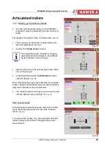
Both cameras must now be aligned against the reflec-
tors on the trailer coupling ring.
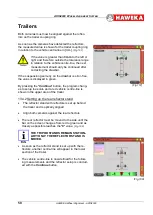
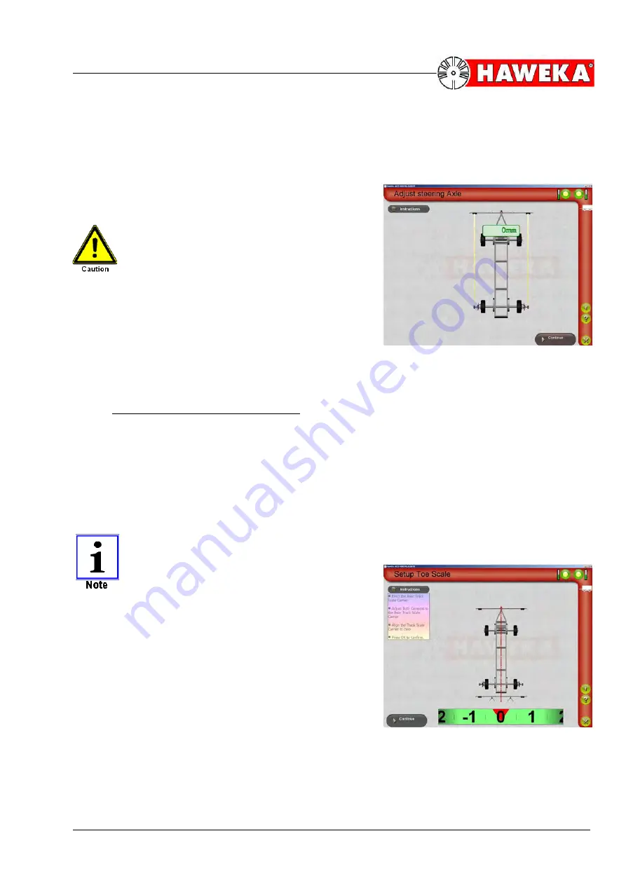
As soon as the cameras have detected the reflectors,
the measured value is shown for the trailer coupling ring
in relation to the vehicle centre-line in [mm].
(Fig. 107)
If the value is greater than
3 mm
to the left or
right and therefore outside the tolerance range
in relation to the vehicle centre-line, the next
measurement should only be continued after
correcting the drawbar.
If the suspension geometry on the drawbar is error-free,
the value is displayed in green.
By pressing the "
Continue
" button, the program chang-
es to setup toe scale and a red vehicle centre-line is
shown in the upper area of the trailer.
13.4.2 Setting up the rear reflector stand
•
The reflector stand with reflectors is set up behind
the trailer and is optically aligned.
•
Align both cameras against the rear reflectors.
•
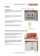
The rear reflector must be moved to the side until the
bar on the screen changes from red to green and as
closely as possible reaches the "
0
" value.
(Fig. 108)
THE TRIPOD STANDS REMAIN STATION-
ARY! ONLY THE REFLECTOR STAND IS
MOVED.
•
As soon as the reflector stand is set up with the re-
flectors, another centre-line will appear in the lower
section of the trailer.
•
The vehicle centre-line is now defined for the follow-
ing measurements and the reflector setup is conclud-
ed with the
Continue
button.
(Fig.108)
(Fig.107)

