AXIS4000
W
HEEL
A
LIGNMENT
S
YSTEM
HAWEKA Wheel Alignment –AXIS4000
38
10 Rear axle measurement
10.1 Measuring the camber
The front axle has been measured and adjusted!
THE CAMERA WHEEL ALIGNMENT
CLAMPS MUST BE REPLACED ON THE
REAR WHEELS WITH LONG MAGNETIC
FEET (315 MM LONG).
•
To do this, loosen the knurled screws and replace the
magnetic feet.
•
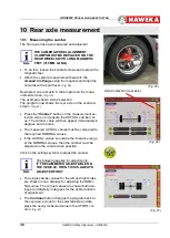
Attach the camera measurement heads to the
cleaned
rim flange
using the magnets and align the
cameras with a spirit level.
(Fig. 65)
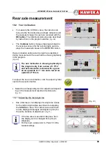
Now select one rear axle in the program on the meas-
urement screen.
(Fig. 66)
The example shows: Axle 2 selection
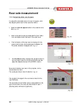
The program now shows the rear axle on the overview
screen.
(Fig. 67)
•
Press the "
Camber
" button on the measurement se-
lection screen to measure the ACTUAL camber val-
ue. The camber value will then appear immediately in
degrees and minutes.
•
The measured ACTUAL values must be compared to
the required NOMINAL values.
•
If the ACTUAL values lie outside the tolerance range
of the NOMINAL values, then the camber must be
adjusted on the vehicle when possible.
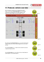
Click on the settings symbol to adjust the camber.
The following applies for adjustments:
IF THE CAMBER IS ADJUSTABLE ON
THE VEHICLE, THEN THIS IS ALWAYS
ADJUSTED FIRST.
•
The single camber values for the left and right sides
are shown on two displays for adjusting the NOMI-
NAL value. The current values are shown both ana-
logue and digitally in degrees for the entire duration
of adjustment.
•
The
Continue
button changes the program back to
the overview screen for the selected axle and dis-
plays the newly measured value in the AFTER col-
umn.
(Fig. 67)
Axle 2 selection (rear axle)
(Fig. 66)
(Fig. 67)
(Fig. 65)


