


Programmable logic valve control
type PLVC 16
D 7845
Programmable logic
valve control
February 2006-00
HAWE HYDRAULIK
SE
STREITFELDSTR. 25 • 81673 MÜNCHEN
5
© 2000 by HAWE Hydraulik
1.
General information
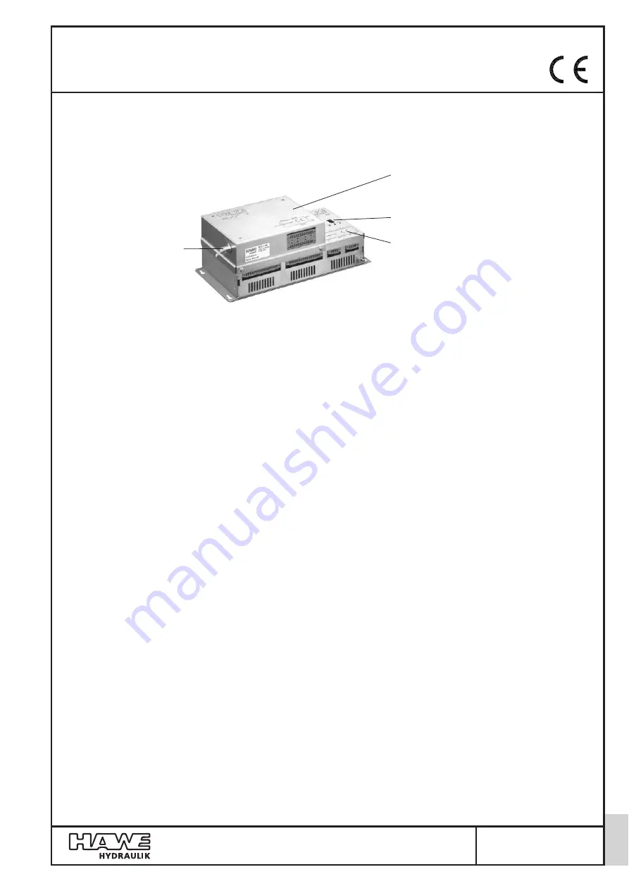
Extension module with
- Receiver unit of the radio control (optional)
- Additional inputs/outputs
Basic module with
- Interfaces for CAN-Bus, RS232
- Inputs/Outputs
- Hardware Emergency-Stop loop
Diagnosis display
Antenna socket
for radio control
(optional)
See also other electronic valve controls/accessory:
Type PLVC 2
acc. to D 7845-2
Type PLVC 4
acc. to D 7845-4
Type PLVC-CAN
acc. to D 7845-Z
The programmable logic valve control of type PLVC 16 consists of a complex PLC-enabled micro-control unit with integrated
amplifiers for mobile and stationary hydraulic applications.
The wide range of possible applications includes, among others:
'
Cranes, crane systems
'
Construction machines
'
Complex hoisting equipment
'
Logging equipment
'
Hydraulic clamping systems for machine tools
'
Presses
The various control tasks are realized through:
'
A modular system with extension and supplementary modules
- Basic module
- Extension module (additional inputs/outputs, receiver for radio control) (optional)
- Text display for diagnosis, and parameterization (via CAN-Bus)
- Large display for diagnosis, and parameterization (via CAN-Bus)
- CAN-Bus controlled power relay
'
Flexible programmability according to IEC 61131-3 standard (PLC-programming via instruction list (IL), function block diagram
(FBD) or structured text (ST))
'
Various interfaces (RS232, CAN-Bus)
'
Free parameterization of all outputs, as well as complete diagnosis capability and short-circuit protection
'
Remote diagnosis via modem or mobile phone
'
Combination of multiple PLVC’s via CAN-Bus within one integrated unit for the control of complex systems
All relevant standards regarding personal safety, EMC, vibration- and shock-proofness are complied with.
The main performance parameters include furthermore:
(the values in brackets specify the performance range of the basic module)
'
Input
-
Max. 24 (8) digital inputs (for limit switches, pressure switches, push buttons, etc.)
-
Max. 24 (8) analog inputs (for joysticks, potentiometers, sensors such as analog pressure sensors)
-
Emergency-Stop signal (opto-decoupled)
-
4 (1) frequency inputs (for indexing switches, rev. counter, incremental encoder, etc.)
-
Optionally integrated radio control module (receiver) incl. Emergency-Stop lock
-
Power supply 10 ... 30 VDC, max. 16 A
'
Output
-
Max. 32 (16) outputs for prop. or ON/OFF valves
-
2 analog outputs 0 ... 10 VDC
-
Emergency-Stop signal
-
2 programmable auxiliary voltage outputs (5, 8, 10, 12 VDC, max. 500 mA, e.g. for potentiometer supply)
-
3 Relay outputs
-
7- segment display on basic module for error detection
'
Functional software features
- PLC programming via IL, FBD or ST
- Parameterization during runtime
- CAN-Bus integrated in the operating system


