Haug EN SL, Руководство по эксплуатации
Haug EN SL - Операционный инструкционный мануал для бесплатного скачивания на {вебсайте}. Этот подробный руководство поможет вам правильно использовать продукт, обеспечивая безопасность и эффективность. Скачать инструкцию в формате PDF и быть уверенным в правильном использовании Haug EN SL.
Поделиться
Скачать


Отзывы:
Нет отзывов
Похожие инструкции для EN SL

HDG3000B Series
Бренд: Hantek Страницы: 22

PD-7700
Бренд: Olin Страницы: 31

RIO ZUNI
Бренд: MIOX Страницы: 9

LGS470
Бренд: OWI Страницы: 1

1200587
Бренд: Radio Shack Страницы: 10

SMCVB-K156
Бренд: R&S Страницы: 79

NDS-1535
Бренд: Sound Pro Страницы: 8

KRK-13
Бренд: Kenwood Страницы: 9
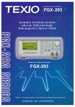
TEXIO FGX-293 Series
Бренд: Kenwood Страницы: 4

FM Transceiver TK-481
Бренд: Kenwood Страницы: 2

TK-2200
Бренд: Kenwood Страницы: 42

FM Transceiver TK-481
Бренд: Kenwood Страницы: 55

TK-2200
Бренд: Kenwood Страницы: 10

NEXEDGE NX-200
Бренд: Kenwood Страницы: 136

FM Transceiver TK-481
Бренд: Kenwood Страницы: 39

NEXEDGE NX-200
Бренд: Kenwood Страницы: 2

NEXEDGE NX-200
Бренд: Kenwood Страницы: 172

TK-2200
Бренд: Kenwood Страницы: 43


