HASHIMA HI-360DS, Руководство по эксплуатации
HASHIMA HI-360DS - это профессиональное оборудование с высокой производительностью. У нас вы можете загрузить инструкцию по эксплуатации бесплатно с нашего веб-сайта. Получите доступ к руководству пользователя, чтобы настроить и использовать свою машину в полную силу. Скачайте сейчас с manualshive.com.
Поделиться
Скачать


Отзывы:
Нет отзывов
Похожие инструкции для HI-360DS
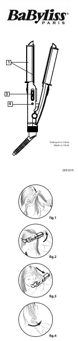
GPB007E
Бренд: BaByliss Страницы: 3

HS-107146.2
Бренд: Waves Страницы: 72

HP4696/27
Бренд: Philips Страницы: 8

HP4666/22
Бренд: Philips Страницы: 7

HP4667/05
Бренд: Philips Страницы: 8

HP4666/15
Бренд: Philips Страницы: 8

BEL0747
Бренд: Beldray Страницы: 16

CR 5027
Бренд: camry Страницы: 5

CR 5024
Бренд: camry Страницы: 76

PRO 230 NANO 0460
Бренд: SEVERIN Страницы: 1

HC 6815
Бренд: SEVERIN Страницы: 4

P8401
Бренд: Imetec Страницы: 76

WAVE MASTER
Бренд: VALERA Страницы: 4

918685000
Бренд: Taurus Страницы: 57

PV1500C ACTIVA
Бренд: UFESA Страницы: 58

DONNA+
Бренд: Gammapiu Страницы: 104

VAPORSTYLE JDL-201
Бренд: Jean Louis David Страницы: 40

SI-100577
Бренд: Waves Страницы: 31


