background image

R

10515-0002E

08/2015

LIMITED ONE YEAR WARRANTY

HARRIS CORPORATION (COMMUNICATION SYSTEMS)

FROM HARRIS TO YOU - This warranty is extended to the original buyer and applies to all Harris Corporation equipment purchased and

employed for the service normally intended, except those products specifically excluded.

NOTE: Terms and conditions of the standard warranty may be superseded by the terms and conditions of your contract.

WHAT WE WILL DO - If your Harris Corporation equipment purchased from us fails in normal use because of a defect in workmanship or

materials within one year from the date of shipment, we will repair or replace (at our option) the equipment or part with new, reconditioned,

or remanufactured equipment or parts without charge to you, at our authorized repair center or factory.

WHAT YOU MUST DO - You must notify us promptly of a defect within one year from date of shipment. Assuming that Harris concurs that

the complaint is valid, and is unable to correct the problem without having the equipment shipped to Harris:

Customers with equipment purchased for use outside the United States must obtain a Return Material Authorization (RMA) 
Number for the return of the defective equipment or part to our factory in Rochester, NY, U.S.A., for repair or replacement. 
You must prepay all transportation, insurance, duty and customs charges. We will pay for return to you of the repaired/
replaced equipment or part, C.I.F. destination; you must pay any duty, taxes or customs charges.

Customers with equipment purchased for use in the United States must obtain an RMA number, properly pack, insure, 
prepay the shipping charges and ship the defective equipment or part to our factory or to the Authorized Warranty Repair 
Center indicated by us.

RMA may be obtained using our Premier Website 

https://tcpremier.harris.com

Shipping instructions will be provided with the RMA confirmation.

Harris Product Service: Phone (585) 242-3561, Toll-free (866) 264-8040, Fax: 585-242-4483

Harris will repair or replace the defective equipment or part and pay for its return to you, provided the repair or replacement is due to a

cause covered by this warranty.

WHAT IS NOT COVERED - We regret that we cannot be responsible for:

Defects or failures caused by buyer or user abuse or misuse.

Units that have been misused, neglected, or damaged by accident.

Defects or failures caused by unauthorized attempts to repair or alter the equipment in any way by persons other than Harris.

Includes units that have been disassembled

Damage caused by leaking batteries

Consequential damages incurred by a buyer or user from any cause whatsoever, including, but not limited to improper 
packaging, transportation, non-Harris repair or service costs, downtime costs, costs for substituting equipment or loss of 
anticipated profits or revenue.

The performance of the equipment when used in combination with equipment not purchased from Harris.

HARRIS MAKES NO OTHER WARRANTIES BEYOND THE EXPRESS WARRANTY AS CONTAINED HEREIN. ALL 
EXPRESS OR IMPLIED WARRANTIES OF FITNESS FOR A PARTICULAR PURPOSE OR MERCHANTABILITY ARE 
EXCLUDED.

SERVICE WARRANTY - Any repair service performed by Harris under this limited warranty is warranted to be free from defects in material

or workmanship for sixty days from date of repair. All terms and exclusions of this limited warranty apply to the service warranty.

IMPORTANT - Customers who purchased equipment must obtain an RMA before shipping the defective equipment to us. Failure to obtain

an RMA before shipment may result in a delay in the repair/replacement and return of your equipment.

IF YOU HAVE ANY QUESTIONS - Concerning this warranty, please refer to Harris Terms & Conditions of Repair at 

http://www.rfcomm.harris.com/frequentlyrequesteditems.asp. 

Содержание RF-7800W-OU470

Страница 1: ...our Premier Website https tcpremier harris com Shipping instructions will be provided with the RMA confirmation Harris Product Service Phone 585 242 3561 Toll free 866 264 8040 Fax 585 242 4483 Harris...

Страница 2: ...EAR99 Information and descriptions contained herein are the property of Harris Corporation Such information and descriptions may not be copied or reproduced by any means or disseminated or distribute...

Страница 3: ......

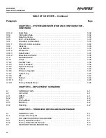
Страница 4: ...ronmental and Line of Sight Concerns 2 1 2 1 2 Link Availability 2 1 2 1 3 System Configuration 2 1 2 1 4 Co location 2 2 2 2 INSTALLATION REQUIREMENTS 2 2 2 3 PRE INSTALLATION CONFIGURATION 2 2 2 3 1...

Страница 5: ...3 6 2 2 SSH 3 9 3 6 3 Local Users Role Based Authentication 3 9 3 6 3 1 Viewing User Accounts 3 9 3 6 3 2 Adding a User Account 3 9 3 6 3 3 Changing a User Account 3 9 3 6 3 4 Deleting a User 3 9 3 6...

Страница 6: ...ed Secret Hash 3 20 3 8 8 4 X 509 Authentication 3 20 3 8 8 5 SC MAC Address 3 20 3 8 9 Interference Mitigation 3 20 3 8 9 1 DFS Action 3 21 3 8 9 2 Antenna Gain 3 21 3 8 9 3 EIM Detection 3 21 3 8 9...

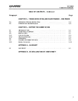
Страница 7: ...3 39 3 10 1 Script 3 39 3 10 2 Security Files 3 39 3 10 3 GUI Localization 3 39 3 10 4 Spectrum Sweep 3 40 3 10 5 Network 3 40 3 10 6 Firmware Upgrade 3 41 3 10 7 System Log 3 43 3 10 8 BIT 3 43 3 10...

Страница 8: ...TING 5 4 5 5 PREVENTIVE MAINTENANCE 5 5 CHAPTER 6 SUPPORT DOCUMENTATION 6 1 INTRODUCTION 6 1 6 2 ADDITIONAL SUPPORT 6 1 6 3 PARTS LISTS 6 1 6 3 1 Units and Cables 6 3 6 3 2 Attaching Hardware 6 4 6 4...

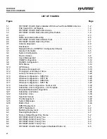
Страница 9: ...Management 3 19 3 12 Throughput vs Number of Hops 3 22 3 13 Latency Increase per Hop 3 22 3 14 Wireless Configuration SPMP SC 3 24 3 15 Wireless Configuration SPTP SC 3 25 3 16 Wireless Configuration...

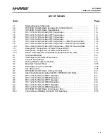
Страница 10: ...l Width 1 12 1 12 Example RF Frequencies 20 MHz Channel Width 1 13 1 13 Notice ETSI Recommended Safe Separation Distance RF 1 13 2 1 Tools and Materials 2 2 3 1 IP Management Interface Parameters 3 2...

Страница 11: ...viii RF 7800W TABLE OF CONTENTS R This page intentionally left blank...

Страница 12: ...aces of the equipment may be in excess of 65 C the point at which personnel could be burned Extreme caution should be used when working with any hot assemblies for example power supply or power amplif...

Страница 13: ...directly related to specific procedures or equipment These precautions are oriented toward the maintenance technician However all personnel must understand and apply these precautions during the many...

Страница 14: ...st static sensitive devices contain protective circuitry several precautionary steps should be taken to avoid the application of potentially damaging voltages to the inputs of the device To protect st...

Страница 15: ...xii RF 7800W SAFETY SUMMARY R This page intentionally left blank...

Страница 16: ...e RF 7800W OU50x is 4 4 to 5 875 GHz The radio models support four channel bandwidths 5 10 20 40 MHz in both SPTP and SPMP modes of operation with operating frequency selection in increments of 0 5 MH...

Страница 17: ...na Table 1 2 RF 7800W HCLOS Radio Ancillary Kit 12069 3030 01 Item Name Part Number Quantity Kit Midspan Injector Gigabit PoE All Regions 12069 3800 01 1 Bracket Assembly Mounting Radio Antenna 12069...

Страница 18: ...lia New Zealand UK and Europe Figure 2 3 shows the PoE Injector connector interface 1 3 1 2 Mast Mount Bracket A bracket assembly 12069 3810 01 can be used to mount the radio antenna to an existing ma...

Страница 19: ...200 0019 IN DATA PoE INJECTOR PORTS FRONT VIEW DETAIL AC POWER CABLE USA OUT CONNECT TO RF 7800W RADIO IN CONNECT TO ETHERNET NETWORK PoE INJECTOR USA NEMA 5 15R TO AUSTRALIA NEW ZEALAND ADAPTER NEMA...

Страница 20: ...contains all of the RF and digital electronics Power delivery is accomplished via an IEEE 802 3at PoE standard power injector 1 4 1 Radio Dimension and Weight Information Figure 1 3 shows the dimensi...

Страница 21: ...R 1 4 2 Radio Mounting Hole Pattern Figure 1 4 shows the RF 7800W HCLOS radio mounting hole pattern Figure 1 4 RF 7800W HCLOS Radio Mounting Hole Pattern 2 87 IN 7 3 CM 10 92 IN 27 7 CM 3 93 IN 10 CM...

Страница 22: ...Hz Receive Sensitivity 98 dBm best Transmit Power 18 dBm 4 4 4 7 GHz 20 dBm 4 7 4 9 GHz 22 dBm 4 9 5 875 GHz Max per port Modulation Binary Phase Shift Keying BPSK Quadrature Phase Shift Keying QPSK 1...

Страница 23: ...generates uses and can radiate radio frequency energy and if not installed and used in accordance with the instruction manual may cause harmful interference to radio communications Operation of this e...

Страница 24: ...8 9 1 In order to ensure that the radio remains on designated frequencies e g due to a DFS induced frequency change Frequency Ranges must be defined Refer to Paragraph 3 8 4 4 Refer to Table 1 6 FCC 5...

Страница 25: ...el Width In order to ensure that the radio remains on designated center frequencies e g due to EIM induced frequency change Frequency Ranges must be defined Refer to Paragraph 3 8 4 4 Refer to Table 1...

Страница 26: ...4945 4940 4950 4950 4945 4955 4955 4950 4960 4960 4955 4965 4965 4960 4970 4970 4965 4975 4975 4970 4980 4980 4975 4985 4985 4980 4990 Table 1 10 FCC 4 940 4 990 GHz Band RF Frequencies 20 MHz Channel...

Страница 27: ...F Frequencies The nominal center frequencies are defined as follows a 10 MHz 5725 n 2 5 MHz where n 2 to 58 b 20 MHz 5725 n 2 5 MHz where n 4 to 56 In order to ensure that the radio remains on designa...

Страница 28: ...d EU Declaration of Conformity A full copy of the Declaration of Conformity can be found in Appendix B Table 1 12 Example RF Frequencies 20 MHz Channel Width RF Frequency MHz Frequency Range MHz Begin...

Страница 29: ...1 14 RF 7800W GENERAL INFORMATION R This page intentionally left blank...

Страница 30: ...e performed before deploying radios in an unknown or unfamiliar location 2 1 2 Link Availability Harris provides a free tool to users that wish to perform a simple evaluation of a single RF 7800W radi...

Страница 31: ...V H polarized antennas in order to operate at full throughput capacity Harris PN RF 7800W AT2XX The installation site should be free from major twist or sway under wind loading A higher mounting loca...

Страница 32: ...ion configure the Frequency and Channel Size based on frequency availability and select Apply Save All These settings must be the same for all radios that are to be linked See Figure 3 16 e Change the...

Страница 33: ...that is designed to mount the radio and an antenna to a vertical pipe or mast with a diameter of 1 5 to 4 0 inches The radio can be mounted on either side of the bracket but should be installed with...

Страница 34: ...e 2 2 Radio and Antenna Mounting RF 7800W HCLOS RADIO RF 7800W AT201 ONE FOOT ANTENNA PURCHASED SEPARATELY CL 0426 4200 0009 RF CABLE MAST MOUNT BRACKET RF CABLE ETHERNET CABLE PURCHASED SEPARATELY GR...

Страница 35: ...n be helpful to be consistent by connecting RF 1 to the Vertical port and RF 2 to the Horizontal port c Ethernet Cable Connect the weather protected end of an Ethernet cable to the J1 PoE port on the...

Страница 36: ...io Bottom Ports Figure 2 4 RF 7800W HCLOS Radio Top Ports CL 0426 4200 0024 J1 ETHERNET PER IEEE802 3 J1 POE J6 ACC J6 ACCESSORY PINS B A C D E F G H J K GROUND SCREW ATTACH GROUND CABLE PURCHASED SEP...

Страница 37: ...to within a few degrees of line of sight Tighten the bolts back up when finished Loosen the bolts on the mounting bracket s sides to adjust the antenna s elevation If the linked radio is more than 22...

Страница 38: ...2 9 RF 7800W SYSTEM INSTALLATION R Figure 2 5 Antenna Alignment...

Страница 39: ...2 10 RF 7800W SYSTEM INSTALLATION R This page intentionally left blank...

Страница 40: ...three management interfaces see below for an example Refer to the following sections General Radio Configuration Information Paragraph 3 2 Navigating User Interfaces Paragraph 3 3 Basic Information P...

Страница 41: ...missions but is simpler to use The Monitor user group is meant to be used by machine interfaces that only need read access to small set of commands Changes to the radio s configuration are not applied...

Страница 42: ...h the GUI The information dashboard shown in Figure 3 1 can be found at the top of the page and provides important information about the radio s current status Clicking different links in the navigati...

Страница 43: ...agement interfaces are not accessible via SNMP The latest version of the radio s Management Information Base MIB part number 12069 8900 can be found on the Harris Premier site https tcpremier harris c...

Страница 44: ...using GUI CLI and SNMP interfaces 3 5 1 1 MAC Address This is the unique Media Access Control MAC address of the Ethernet port It is set by the factory and not user configurable This address may be r...

Страница 45: ...eters All parameters for Addressing can be accessed using GUI CLI and SNMP interfaces 3 5 2 2 IP Address This is the IP address of the radio s management interfaces The factory default address is 192...

Страница 46: ...3 7 RF 7800W SYSTEM ADMINISTRATION AND CONFIGURATION R Figure 3 4 System Configuration...

Страница 47: ...host X 509 certificate and private key pair are pre installed but can be overwritten with a user generated certificate Ahost X 509 certificate and private key pair must be loaded in order to use HTTPS...

Страница 48: ...le Based authentication defined by the account groups If User Based authentication is required a separate RADIUS server can be used to expand the number of possible user accounts beyond the five accou...

Страница 49: ...3 10 RF 7800W SYSTEM ADMINISTRATION AND CONFIGURATION R Figure 3 6 Users Management...

Страница 50: ...at control whether the agent can perform read write or both types of operations on SNMP objects in the radio The default communities are public and private with read only and read write operations per...

Страница 51: ...rk VLAN Identification ID 3 6 6 Remote Users User Based Authentication The subsections below describe RADIUS Management Interfaces configuration parameters Click on the blue RADIUS Configuration link...

Страница 52: ...of the GUI links to a summary that indicates the current status of configuration parameters against the corresponding requirements Once all criteria is met FIPS Mode can be activated A reboot is promp...

Страница 53: ...current time 3 7 1 2 Polling Interval This interval defines the period of time between polls to the SNTP server for time Periodic polling is required to synchronize time with other network devices The...

Страница 54: ...GPS antenna is properly attached and configured and has good line of sight to enough GPS satellites the position of the radio is made available 3 7 2 4 GPS Status A more detailed overview of the inter...

Страница 55: ...e for feeding back information about the quality of the radio link to the SC which allows the SC to optimize transmissions 3 8 2 Radio Mode The radio has two RF ports which can be used either together...

Страница 56: ...to if the radio was not aware of the presence of the PA 3 8 3 4 Statistics The actual transmit power depends on a number of things including Automatic Transmit Power Control ATPC settings and dynamic...

Страница 57: ...es to the network for each MAC address that is located on the SS side of the link in order to make the network aware of the new location of the nodes Refer to Paragraph 4 3 for additional Roaming info...

Страница 58: ...g the maximum link distance if the installation is fixed site in order to improve latency The default value for this is 50 km 31 miles and must be adjusted to be greater than the actual link distance...

Страница 59: ...icate the radios that are configured to link over the air The radio authenticates the certificate of its link partner before finishing the link up process Refer to RF 7800W OU47x OU50x Security Operat...

Страница 60: ...e used as the threshold for interference detection The Min Burst Rate should be set to the lowest value that achieves the necessary throughput for a particular Link SNMP traps are sent to network mana...

Страница 61: ...f potential parents and select the one that should provide the best throughput Refer to Paragraph 3 8 4 3 Throughput decreases when data travels through multiple hops since the data needs to be transm...

Страница 62: ...the SC will transmit multicast data for SPMP A short Registration Period will decrease the potential unicast throughput and increase the potential multicast throughput A long Registration Period will...

Страница 63: ...3 24 RF 7800W SYSTEM ADMINISTRATION AND CONFIGURATION R Figure 3 14 Wireless Configuration SPMP SC...

Страница 64: ...3 25 RF 7800W SYSTEM ADMINISTRATION AND CONFIGURATION R Figure 3 15 Wireless Configuration SPTP SC...

Страница 65: ...3 26 RF 7800W SYSTEM ADMINISTRATION AND CONFIGURATION R Figure 3 16 Wireless Configuration SPMP SS...

Страница 66: ...3 27 RF 7800W SYSTEM ADMINISTRATION AND CONFIGURATION R Figure 3 17 Wireless Configuration SPTP SS...

Страница 67: ...cess controlled via the unit s MAC Address Link Templates allow an arbitrary number of SS to register with an SC with access controlled via a Station Template Identifier STID and STID Password A Deriv...

Страница 68: ...3 9 2 7 Link Partner IP Address Once the SS radio has successfully linked up with the SC each radio s IP address is made available in the link details of the opposite radio as a convenient way to qui...

Страница 69: ...3 30 RF 7800W SYSTEM ADMINISTRATION AND CONFIGURATION R Figure 3 18 Subscriber Link Configuration Normal Link...

Страница 70: ...3 31 RF 7800W SYSTEM ADMINISTRATION AND CONFIGURATION R Figure 3 19 Subscriber Link Configuration Link Template...

Страница 71: ...ues for both the downlink and uplink The SC uses these values to assist with prioritizing how much traffic is sent over each link when there is not enough transmission time to get all data to all subs...

Страница 72: ...Broadcast and Multicast Non unicast traffic like ARP broadcasts and multicast video streams are transmitted by the SPMP SC during its dedicated broadcast multicast time slot This time slot uses a simi...

Страница 73: ...3 34 RF 7800W SYSTEM ADMINISTRATION AND CONFIGURATION R Figure 3 20 Broadcast Multicast Configuration...

Страница 74: ...goes down an SNMP trap is sent out to indicate the event When an SS radio has successfully completed authentication and registration with the SC there will be a positive indication for a Data Link Whe...

Страница 75: ...3 36 RF 7800W SYSTEM ADMINISTRATION AND CONFIGURATION R Figure 3 21 Subscriber Link Status...

Страница 76: ...when using an external PA such that the values shown correspond with the input of the PA from the antenna Refer to Table 3 6 for descriptions of the Link Status icons See Figure 3 22 3 9 8 3 Data Metr...

Страница 77: ...3 38 RF 7800W SYSTEM ADMINISTRATION AND CONFIGURATION R Figure 3 22 Subscriber Links...

Страница 78: ...the air X 509 authentication can be delivered to the radio via various IP based file transfer mechanisms Refer to RF 7800W OU47x OU50x Security Operation Supplement 10515 0426 4000 for more informati...

Страница 79: ...er distribution or other high power radios See Figure 3 23 NOTE Spectrum Sweep reduces the maximum possible user data throughput by around 10 percent 3 10 5 Network The radio contains some network tes...

Страница 80: ...ions of software When a new version is uploaded it overwrites the inactive version In order to complete the upgrade process the radio must be switched to the new alternate version On SC firmware may b...

Страница 81: ...3 42 RF 7800W SYSTEM ADMINISTRATION AND CONFIGURATION R Figure 3 24 File Management...

Страница 82: ...etwork SysLog server See Figure 3 25 Additional information pertaining to the system messaging interfaces including a comprehensive list of system messages is available in the RF 7800W OU47x OU50x Sys...

Страница 83: ...ADMINISTRATION AND CONFIGURATION R 3 10 9 Reboot Occasionally an Administrator may wish to remotely reboot the radio All three management interfaces provide the ability to do this Figure 3 26 Built I...

Страница 84: ...ge could result in dropping communication to a radio that is being configured For example changing the maximum transmit power of a radio from over its active link could result in the link dropping By...

Страница 85: ...3 46 RF 7800W SYSTEM ADMINISTRATION AND CONFIGURATION R This page intentionally left blank...

Страница 86: ...on the number of required Subscriber Stations SS 4 2 1 SPMP Simple Point to Multipoint SPMP supports an arbitrary number of SS up to 124 per Sector Controller SC but is optimized for deployments of le...

Страница 87: ...gured to use the same Link Template See Figure 4 3 the panels of the figure are described below Panel 1 Multiple SS are linked directly to the SC Panel 2 SS N relays through SS 2 Panel 3 SS N and SS 1...

Страница 88: ...from SC 2 improves and the signal from SC N becomes present Panel 3 The SS registers to SC 2 since it has the best signal while the signal from SC N improves and the signal from SC 1 degrades Panel 4...

Страница 89: ...4 4 RF 7800W DEPLOYMENT SCENARIOS R This page intentionally left blank...

Страница 90: ...side pane of the GUI 5 2 1 Factory Reset Procedure See Figure 5 1 It may be necessary to reset to the factory IP address e g due to lost admin user name and password This can be accomplished by having...

Страница 91: ...mmand save defaultconfig and press Enter to ensure that all parameters are set to default values k Enter the following commands to set a new IP address A 192 168 26 2 prompt is shown at each step 1 se...

Страница 92: ...IP address is the same as another device on the local network Symptom The radio s management interfaces HTTP HTTPS Telnet SSH SNMP are not accessible to a computer on the same network Solution Change...

Страница 93: ...radio problem c Are both radio antennas generally pointing towards each other 1 Test this with a compass not included or use a long range sighting scope not included d Are both radios on the same Fre...

Страница 94: ...iguration Wireless Traffic Flow Security Configuration 2 If the Shared Secret Hash values are not the same the Shared Secret was not entered properly n Is there a problem with X 509 authentication 1 S...

Страница 95: ...5 6 RF 7800W TROUBLESHOOTING AND MAINTENANCE R This page intentionally left blank...

Страница 96: ...5830 toll free 866 264 8040 or visit the Harris Support web site at https tcpremier harris com 6 3 PARTS LISTS The following provides parts lists for the systems Figure 6 1 shows the family tree for...

Страница 97: ...TY LINE OF SIGHT SYSTEM KIT MIDSPAN INJECTOR GIGABIT POE 12069 3800 01 BRACKET ASSY MOUNTING RADIO ANTENNA 12069 3810 01 RF COAXIAL CABLE ASSY 12069 3940 A20 HCLOS RADIO TAN 12069 3000 04 CL 0426 4200...

Страница 98: ...dio 14304 12069 3000 01 OU470 12069 3000 03 OU500 12069 3000 04 OU471 12069 3000 06 OU501 Figure 6 5 Ancillary Kit Broadband Ethernet Radio 14304 12069 3030 01 Figure 6 5 Kit MidSpan Injector Power ov...

Страница 99: ...with RF 7800W HCLOS Radio Letter Code Item Name Description Quantity Part Number Figure Number A Flat Washer 281 x 625 x 065 12 MS15795 810B Figure 6 5 B Lock Washer 1 4 Inch Split 12 MS35338 139B Fi...

Страница 100: ...le operating with the maximum specified gain settings FCC 4 94 4 99 GHz SPTP Operation Model Number Gain dBi Description Max Tx Power dBm 5 MHz 10 MHz 20 MHz RF 7800W AT206 8 Omni 22 22 22 RF 7800W AT...

Страница 101: ...RF 7800W AT201 21 10 7 4 1 10 RF 7800W AT202 26 6 9 6 10 RF 7800W AT203 30 4 4 10 4 Table 6 6 FCC 5 250 5 350 GHz SPMP Operation Model Number Gain dBi Description Max Tx Power dBm 5 MHz 10 MHz 20 MHz...

Страница 102: ...10 22 22 22 22 RF 7800W AT202 26 6 22 22 22 22 RF 7800W AT203 30 4 4 22 22 22 22 FCC 5 725 5 850 GHz SPMP Operation Model Number Gain dBi Description Max Tx Power dBm 5 MHz 10 MHz 20 MHz 40 MHz RF 780...

Страница 103: ...ole Rx I Per TIA EIA 422 H Console Tx O Per TIA EIA 422 J Console Tx O Per TIA EIA 422 K Console Ground N A Per TIA EIA 422 Table 6 10 Connectors and Mating Connector Part Numbers Chassis Connector Ma...

Страница 104: ...aring from Global Positioning System GPS or compass B bit A binary digit that can have a value of 0 or 1 BIT Built in Test BPSK Binary Phase Shift Keying C C Celsius CA Certification Authority CAGE Co...

Страница 105: ...ynamic Frequency Selection DL Downlink E EIM Enhanced Interference Mitigation EIRP Effective Isotropic Radiated Power Elevation Vertical direction in degrees EMR Electromagnetic Radiation EN European...

Страница 106: ...second I ID Identification IEEE Institute of Electrical and Electronics Engineers in Inches IN LBS Inch Pounds INE Inline Network Encryptor IP Internet Protocol J K kg Abbreviation for kilogram or on...

Страница 107: ...on O OFDM Orthogonal Frequency Division Multiplexing OLOS Optical Line of Sight P PA Power Amplifier PC Personal Computer PIR Peak Information Rate PLL Phase Lock Loop PMP Point to Multiple Points PoE...

Страница 108: ...o Multiple Point SPTP Simple Point to Point SS Subscriber Station SSH Secure Shell SSL Secure Socket Layer STC Space Time Coding STID Station Template Identifier T TDD Time Division Duplexing TELNET T...

Страница 109: ...A 6 RF 7800W APPENDIX A R V Continued VLAN Virtual Local Area Network VSWR Voltage Standing Wave Ratio W W Watts Width WAN Wide Area Network X Z...

Страница 110: ...B 1 RF 7800W APPENDIX B R APPENDIX B EU DECLARATION OF CONFORMITY...

Страница 111: ...B 2 RF 7800W APPENDIX B R This page intentionally left blank...

Страница 112: ...DATE GENERAL EXCELLENT GOOD FAIR POOR TEXT SETUP ALIGNMENT INST TROUBLESHOOTING INST TABLES ILLUSTRATIONS PARTS LISTS SCHEMATIC DIAGRAMS GENERAL COMMENTS Please include your suggestions for improveme...

Страница 113: ...S REPLY MAIL FIRST CLASS PERMIT NO 4033 ROCHESTER N Y POSTAGE WILL BE PAID BY ADDRESSEE NO POSTAGE NECESSARY IF MAILED IN THE UNITED STATES NAME DATE COMPANY ADDRESS CITY STATE ZIP COUNTRY PHONE NUMBE...

Страница 114: ...Communication Systems 1680 University Ave Rochester NY USA 14610 Tel 585 244 5830 Fax 585 242 4755 www harris com...

Страница 115: ...A CH WID X FAILOVER OFF 4 SPMP SS 1 FREQ A CH WID X FAILOVER ON SPMP SS 2 FREQ A CH WID X FAILOVER OFF SPMP SS N FREQ A CH WID X FAILOVER OFF 2 SPMP SC FREQ A CH WID X SPMP SS 1 FREQ A CH WID X FAILO...

Страница 116: ...B CH WID Y SPMP SC N FREQ C CH WID Z SPMP SS FREQ AUTO CH WID AUTO SPMP SC 1 FREQ A CH WID X SPMP SC 2 FREQ B CH WID Y SPMP SC N FREQ C CH WID Z SPMP SC 1 FREQ A CH WID X SPMP SC 2 FREQ B CH WID Y SP...

Страница 117: ...E INJECTOR ALL REGIONS GROUND SCREW BOTTOM VIEW DETAIL USA NEMA 5 15R TO AUSTRALIA NEW ZEALAND ADAPTER NEMA 5 15R TO EUROPE CEE 7 7 ADAPTER NEMA 5 15R TO UK BS 1363 ADAPTER USER DOCUMENTATION CD ROM 1...

Отзывы: