background image

MM-015371-001, Rev. C 


REGULATORY AND SAFETY INFORMATION 

1.1  SAFETY SYMBOL CONVENTIONS 

The following conventions are used in this manual to alert the user to general safety precautions that must 
be observed during all phases of operation, installation, service, and repair of this product. Failure to 
comply with these precautions or with specific warnings elsewhere violates safety standards of design, 
manufacture, and intended use of the product. Harris Corporation assumes no liability for the customer's 
failure to comply with these standards. 


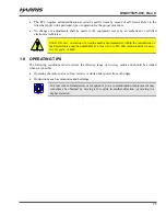
The WARNING symbol calls attention to a procedure, practice, or the like, which, 
if not correctly performed or adhered to, could result in personal injury. Do not 
proceed beyond a WARNING symbol until the conditions identified are fully 
understood or met. 


CAUTION


The 

CAUTION

 symbol calls attention to an operating procedure, practice, or the like, 

which, if not performed correctly or adhered to, could result in damage to the 
equipment or severely degrade equipment performance. 


The 

NOTE

 symbol calls attention to supplemental information, which may improve 

system performance or clarify a process or procedure. 

1.2  RF ENERGY EXPOSURE AWARENESS AND CONTROL 

INFORMATION FOR FCC OCCUPATIONAL USE REQUIREMENTS 

Before using the two-way mobile radio, read this important RF energy awareness and control 
information and operational instructions to ensure compliance with RF exposure guidelines. 


This radio is intended for use in occupational/controlled conditions, where users 
have full knowledge of their exposure and can exercise control over their 
exposure to remain below RF exposure limits. This radio is NOT authorized for 
general population, consumer, or any other use. 


CAUTION


Changes or modifications not expressly approved by Harris could void the user's 
authority to operate the equipment. 

This two-way radio uses electromagnetic energy in the radio frequency (RF) spectrum to provide 
communications between two or more users over a distance. It uses RF energy or radio waves to send and 
receive calls. RF energy is one form of electromagnetic energy. Other forms include, but are not limited 
to, electric power, sunlight, and x-rays. RF energy, however, should not be confused with these other 
forms of electromagnetic energy, which, when used improperly, can cause biological damage. Very high 
levels of x-rays, for example, can damage tissues and genetic material. 

Experts in science, engineering, medicine, health, and industry work with organizations to develop 
standards for exposure to RF energy. These standards provide recommended levels of RF exposure for 

Содержание M5300

Страница 1: ...Installation and Product Safety Manual MM 015371 001 Rev C Sep 09 M5300 and M7300 Mobile Radios with CH 721 Control Heads VHF and 800 MHz Motorcycle Applications...

Страница 2: ...trademark and IMBE AMBE and AMBE 2 are trademarks of Digital Voice Systems Inc Bird is a registered trademark of Bird Electronic Corporation Microsoft and Windows are registered trademarks of Microso...

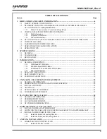
Страница 3: ...15 3 1 2 800 MHz Band M5300 Radio 15 3 1 3 Dual Band 700 and 800 MHz M7300 Radio 15 3 1 4 General Information 16 3 2 RELATED PUBLICATIONS 18 3 3 REPLACEMENT PARTS 19 3 4 TECHNICAL ASSISTANCE 19 4 UNP...

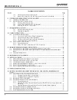
Страница 4: ...NS 54 11 1 CONNECTING A HEADSET TO THE RADIO WITHOUT BELT BOX 54 11 2 CONNECTING A HEADSET PORTABLE RADIO TO THE MOBILE RADIO WITH BELT BOX 56 11 3 HEADSET OPERATION 58 12 MICROPHONE ATTACHMENT 59 13...

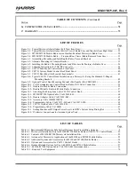
Страница 5: ...dio CAN Cable Connection 53 Figure 11 1 Headset to Mobile Radio Connection 55 Figure 11 2 Headset Portable Radio to Mobile Radio Connection 57 Figure 12 1 Attaching the Microphone to the CH 721Control...

Страница 6: ...L INFORMATION FOR FCC OCCUPATIONAL USE REQUIREMENTS Before using the two way mobile radio read this important RF energy awareness and control information and operational instructions to ensure complia...

Страница 7: ...compliance requirements 1 3 COMPLIANCE WITH RF EXPOSURE STANDARDS The M5300 and M7300 two way mobile radios are designed and tested to comply with a number of national and international standards and...

Страница 8: ...ion unless it is reprogrammed per the procedures presented in Section 15 3 The dual band M7300 mobile radio can operate on both 700 and 800 MHz bands However as of the publication of this manual motor...

Страница 9: ...hile fueling the vehicle If the radio is mounted in the trunk of the vehicle DO NOT carry containers of fuel in the trunk Areas with potentially explosive atmosphere are often but not always clearly m...

Страница 10: ...ordance with the rules and regulations of the Federal Communications Commission FCC Operators of two way radio equipment must be thoroughly familiar with the rules that apply to the particular type of...

Страница 11: ...mitter within the jurisdiction of the United States may be punishable by a fine of up to 10 000 imprisonment for up to two 2 years or both 1 8 OPERATING TIPS The following conditions tend to reduce th...

Страница 12: ...40 to 185 Fahrenheit 40 to 85 Celsius Altitude 15 000 feet 4572 meters maximum DC Supply Voltage Operating Range 13 6 Vdc 10 Normal range per TIA 603 DC Supply Current Requirements Receive includes c...

Страница 13: ...iver Sensitivity VHF P25 Mode TIA 102 Method 116 dBm minimum at 5 BER static VHF EDACS Conventional Modes 119 dBm minimum at 12 dB SINAD 25 kHz channels 800 MHz OTP Mode 111 dBm minimum at 1 BER stati...

Страница 14: ...ate 2400 bps 2 3 REGULATORY FCC Type Acceptance VHF Radio OWDTR 0055 E 700 800 MHz Radio OWDTR 0051 E Applicable FCC Rules Part 15 and Part 90 Industry Canada Certification VHF Radio 3636B 0055 700 80...

Страница 15: ...io systems standards 800 MHz Enhanced Digital Access Communications System EDACS trunked radio networks 800 MHz ProVoice trunked radio networks 800 MHz APCO Project 25 Phase I compliant Common Air Int...

Страница 16: ...control of the mobile radio an internal high power audio amplifier to drive an externally connected speaker and a front panel microphone connector The CH 721 System control head also has a 12 button n...

Страница 17: ...on APCO Project 25 Phase I compliant Common Air Interface P25 CAI trunked radio networks and operation in a talk around mode in accordance with the APCO Project 25 Phase I standard P25 radio systems u...

Страница 18: ...rty 3 2 RELATED PUBLICATIONS The following publications contain additional information about the M5300 and M7300 mobile radios M5300 Quick Guide for EDACS ProVoice and Conventional Modes MM 013232 001...

Страница 19: ...PC_tac harris com International Phone Number 1 434 455 6403 Fax Number 1 434 455 6676 E mail PSPC_CustomerFocus harris com 3 4 TECHNICAL ASSISTANCE Should the mobile radio or control head require repa...

Страница 20: ...19 for contact information to discuss and arrange the return of the equipment to Harris for replacement Any unauthorized attempts to repair or modify this equipment will void the warranty and could c...

Страница 21: ...8 0004 M5300 catalog number MAHK NCP9F M7300 catalog number MAMW NCP9F Standard Microphone part number MC 101616 041 Included with catalog numbers MAHK NMC7Z and MAMW NMC7Z or DTMF Microphone part num...

Страница 22: ...of these installation kits Contents are identical except MAHK NZN7X for the M5300 radio and MAMW NZN7X for the M7300 radio both include Accessory Cable 19B802554P24 whereas the other two kits do not c...

Страница 23: ...tainless steel lockwashers 9 1 CA 012365 001 Cable M7200 M7300 M5300 DC Power Includes 1 20 Foot DC Power Cable with straight connector 2 waterproof inline HFB type fuse holders 1 3 amp AGC fuse 1 15...

Страница 24: ...DB 25 accessory connector 20 1 188D6556G1 Hanger Microphone 21 1 CA 012349 002 Cable Headset Adapter Required when Accessory Cable 19B802554P24 is used For additional information see the NOTE that fo...

Страница 25: ...Fed 2 5 dBd Gain LE OM806HDBKTNCDS Antenna 800 MHz High Impedance Voltage End Fed 4 5 OPTIONS AND ACCESSORIES Table 4 4 Additional Options and Accessories for M5300 and M7300 Mobile Radios PART NUMBER...

Страница 26: ...ued replaced by MC 101616 041 Microphone Standard with Conxall Flush Mount 45 Degree Connector MC 101616 041 Microphone Standard with Conxall Flush Mount 90 Degree Connector Included with catalog numb...

Страница 27: ...PTT Switch Harley Davidson SM MCH 72GT Cable Headset Helmet Kit Interface with Rocker PTT Switch and Channel Guard Disable Switch Harley Davidson SM MCH 73GT Cable Headset Helmet Kit Interface with Ro...

Страница 28: ...used Non Insulated Crimp Tool with Wire Cutter similar to Thomas Betts WT 111 M Insulated Terminal Crimp Tool with Wire Cutter similar to Klein 1005 Fuse Holder Crimp Tool similar to Thomas Betts WT 1...

Страница 29: ...d Brackets from Right Side Mobile Antenna CH 721 Control Head Mobile Speaker Weather Resistant Case with M7300 Mobile Radio Inside Microphone Mobile Antenna Weather Resistant Case with M7300 Mobile Ra...

Страница 30: ...er Resistant Motorcycle Radio Case Weather Resistant Case Bottom Square hole in bottom floor of case M7300 Mobile Radio R E A R F R O N T Weather Resistant Case Top Shown Opened Mobile Antenna Case An...

Страница 31: ...the routes for all wiring and cables Particularly consider the connection of the radio for planning purposes The radio and its weather resistant case must be mounted at the rear of the motorcycle just...

Страница 32: ...at severe angles near the connector end Above all after all components are installed verify no cable is under any tension Failure to do so may lead to damaged cables causing intermittent radio operati...

Страница 33: ...inch flatwashers included in Hardware Kit 350A1396G2 Some motorcycle radio brackets have pre drilled holes that will match the four 4 PEM nuts in the Adapter Bracket In this case as illustrated in Fig...

Страница 34: ...case must be towards the front of the motorcycle so it is directly over the square hole in the Case Antenna Bracket 6 Place a 5 16 inch stainless steel flatwasher onto each of the four 5 16 inch stud...

Страница 35: ...is towards the front 4 Secure the bracket to the case s floor using four M6 x 14 mm bolts and four external tooth lockwashers included in Hardware Kit 350A1396G1 Item 5 in Table 4 2 5 Tighten these f...

Страница 36: ...MM 015371 001 Rev C 36 DETAIL VIEWS Made From AA01 MAMW Sh 1 Rev Figure 6 3 Installing the Radio s Mounting Bracket and Filter into the Motorcycle Radio Case...

Страница 37: ...he following section Since the antenna is a high impedance voltage end fed antenna the length of the coaxial cable from the base of the antenna to the radio s TNC antenna connector is critical It cann...

Страница 38: ...reater value of N 6 Shorten the cable by cutting it to the calculated length 7 1 3 Route Cable Crimp On TNC RF Connector and Connect It to the Radio 1 Route the antenna coax cable from the base of the...

Страница 39: ...ev C 39 damage dirt and or metal shavings which may be generated during the mechanical and electrical installation of the radio Temporarily tying the connector and cable end within a small plastic bag...

Страница 40: ...Control Head Front Panel Other controls are same as shown for Scan model Figure 8 2 CH 721 System Model Control Head Front Panel The CH 721 control heads feature a large easy to read 3 line graphical...

Страница 41: ...mounted at the centerline of the motorcycle between the steering handlebars and secured to the handlebars or to the frame just below the handlebars A typical installation is shown in Figure 8 4 The CH...

Страница 42: ...andlebar Partial view Control Head Adapter Bracket Not Supplied Control Head Mounting Bracket FM24841 0001 Included with Mounting Bracket Kit KT 008608 Control Head Mounting Pedestal MACDOS0012 Pedest...

Страница 43: ...l line engine transmission wiring etc Always check to see how far the mounting screws will extend below the mounting surface prior to installation Always deburr drilled holes before installing screws...

Страница 44: ...washer should be adjacent to the screw head and the flat washer should be adjacent to the bracket Turn each screw clockwise as observed from the head of the screw 9 The control head can be positioned...

Страница 45: ...ommended 1 Obtain External Speaker LS102824V10 item 15 in Table 4 2 included in the installation kit 2 Using the above listed guidelines select a mounting location for the speaker 3 Install the speake...

Страница 46: ...controlled switch and the other side of this switch is connected to unswitched and fused vehicle power The required fuse rating is 3 amperes When using this configuration the CH 721 control head s on...

Страница 47: ...er mating CAUTION Do not confuse the radio s DC Power Cable which has a 10 AWG red wire with the control head s DC Power Cable which has a 12 AWG red wire The radio requires much more DC operating cur...

Страница 48: ...terminal to metal contact Tighten securely 11 Apply an approved paint or rust inhibitor over the remaining exposed bare metal surface and around the ring terminal 10 1 3 2 Red Wire and Main Fuse Hold...

Страница 49: ...r and red wire appropriately e g Radio Main Power 15 AMP FUSE 12 Do NOT install a fuse into the fuse holder at this time 13 Crimp an appropriate electrical terminal to the short red wire A corrosion r...

Страница 50: ...he stub nuts 9 Strip approximately inch of insulation from the end of the red wire and crimp a 8 stud ring terminal has yellow insulation to it 10 Obtain one of the waterproof HFB type fuse holders in...

Страница 51: ...ncluded with the control head s DC Power Cable 4 Cut excess length from the white wire and splice the fuse holder into it near the location of the connection point 5 Using an appropriate electrical te...

Страница 52: ...hed and fused 12 volt vehicle power Follow the procedure presented in Section 10 1 4 2 1 except connect the white wire to unswitched battery power instead of switched Accessory power 10 2 CAN CABLE CO...

Страница 53: ...from chafing Figure 10 1 CAN Terminators and Control Head to Radio CAN Cable Connection 5 Route the CAN cable it into the case by passing it through the square hole in the bottom floor case 6 Mate th...

Страница 54: ...elt box follow this procedure 1 Open the motorcycle radio case 2 As illustrated in Figure 11 1 on page 55 connect the male 44 pin D subminiature DB 44 connector of Headset Adapter Cable CA 012349 002...

Страница 55: ...349 002 No connection required to this DB 25 connector Tie and stow it in radio case 4 Conductor Quick Disconnect Jack 4 Conductor Quick Disconnect Plug Y Cable MOTORCYCLE OPERATOR RIDER Motorcycle Ra...

Страница 56: ...ry Cable 19B802554P24 to the female DB 25 connector of the Headset Adapter Cable Tighten the two 2 jackscrews securely 4 Route the Accessory Cable s round 8 pin waterproof connector through the square...

Страница 57: ...tion and Motorcycle PTT Only Pushbutton Switch PTT CG Disable Rocker Switch MOTORCYCLE Accessory Cable 19B802554P24 Headset Adapter Cable CA 012349 002 No connection required to this DB 25 connector T...

Страница 58: ...torcycle is equipped with Headset Helmet Kit Interface Cable option SM MCH 71GT or SM MCK 71GT to transmit simply press and hold the PTT button on the PTT switch then talk into the headset s mic To re...

Страница 59: ...microphone clip as a template drill mounting holes in the surface of the selected location 3 The microphone clip must be grounded to the vehicle s chassis If not mounted to a grounded metal surface co...

Страница 60: ...cable s 44 pin D subminiature connector that mates with the connector on the rear of the radio is identified P1 P2 the cable s 2 pin connector provides connections for an external speaker in a front m...

Страница 61: ...nd Inactive Open 25 INP2 P3 pin 5 Digital Input 2 28 SWA P3 pin 6 Switched A DC Power Output 8 GND P4 pin 1 Chassis ground fused on PK Board at 3 amps 30 DGPS_DATA P4 pin 4 GPS Serial Data This connec...

Страница 62: ...TXENB P4 pin 23 Transmit Enable B 27 EXTMIC P4 pin 24 Pin 27 of the radio s DB 44 connector is the radio s External Mic Audio Input for a headset microphone or any second mic audio source such as a bo...

Страница 63: ...below The cable s male 44 pin D subminiature DB 44 connector identified P1 mates with the female DB 44 connector on the rear of the radio The cable s female DB 25 connector identified J1 mates to the...

Страница 64: ...B 25 connector identified P1 mates to the female DB 25 connector of Headset Adapter Cable CA 012349 002 The cable s round 8 pin waterproof connector identified P2 mates to the motorcycle harness Y cab...

Страница 65: ...ector on one end for connection to the PC s serial port and a male DB 9 connector on the other end for connection to the serial port on the rear of the radio The cable s assembly and wiring diagrams a...

Страница 66: ...equipment to the 25 pin D subminiature DB 25 connector on the rear of the CH721 This cable expands the connections available at the 25 pin connector to three 3 separate connectors The cable s assembl...

Страница 67: ...ol head via a Personal Computer PC This cable has a female DB 9 connector on one end for connection to the PC s serial port and a male DB 9 connector on the other end for connection to the serial port...

Страница 68: ...ol head is not already powered up do so by rotating its on off volume control clockwise out of the detent position 7 Verify the control head has powered up by observing its display If the display is n...

Страница 69: ...rior to jump starting Doing so will prevent damage to the radio system 15 1 CHANGING OPERATING MODE FOR TESTS To complete tests in this section placing the radio in a conventional mode and using an av...

Страница 70: ...nSky measurements Bird Electronic Corp Model 4314B or equivalent with Type N female connectors at input and output ports RF Coaxial Jumper Cable Pasternack Enterprises PE3661 length per CAUTION on pag...

Страница 71: ...nt a reduction in transmit RF output power will be required for EDACS ProVoice conventional and P25 ECP operating modes 15 3 2 Adjusting Maximum Transmit Output Power for EDACS ProVoice Conventional a...

Страница 72: ...013671 020 20 feet Also if the utilized PC is not equipped with a DB 9 serial port connector the use of a suitable adapter will be required such as USB to RS 232 Adapter Cable CN24741 0001 2 Start up...

Страница 73: ...peak reading RF wattmeter is required to measure RF transmit power Otherwise the use of an average responding wattmeter is recommended Recommended wattmeter types are listed in Table 15 1 3 If not al...

Страница 74: ...ty factor of 95 if it is not otherwise specified by the wattmeter manufacturer 9 If the wattmeter reading is within the range record the measured value in the appropriate space on the data collection...

Страница 75: ...wer into the antenna is within 20 of the maximum transmit output power in watts programming performed per Section 15 3 Transmit only for as long as needed to take the measurement then immediately disa...

Страница 76: ...the coaxial cable jumper and wattmeter 14 Permanently connect the cable from the vehicle mounted antenna to the radio s antenna cable by mating the two TNC connectors together Use two pairs of soft ja...

Страница 77: ...as a permanent record of the tested performance of the M5300 M7300 mobile radio installation Clip Here Company Performing Installation Technician Performing Test Date of Test mm dd yyyy Mobile Radio...

Страница 78: ...they are out of the way of casual contact away from sources of extreme heat and wire chafing cannot occur Pay special attention to all RF antenna cables To prevent fumes from entering the vehicle s pa...

Страница 79: ...d by Seller s reasonable efforts the parties will negotiate an equitable adjustment in price Labor to perform warranty service will be provided at no charge during the warranty period only for the Equ...

Страница 80: ...Public Safety and Professional Communications www harrispublicsafety com 221 Jefferson Ridge Parkway Lynchburg VA USA 24501 1 800 528 7711...

Отзывы: