


Chapter 2 System Installation with the Content-
Server 4000 Series
© 2017 Harmonic Inc. All rights reserved.
64
Harmonic MediaGrid Release 4.1
Connecting the Harmonic MediaGrid 4000 System Components
NOTE:
The switches shown in
Figure 2–24
are provided as examples only. Your switches may vary from the
ones shown.
IMPORTANT:
Make sure to use only Harmonic MediaGrid-qualified switches in your Harmonic MediaGrid
system. To find out if a switch is Harmonic MediaGrid-qualified, contact your Harmonic representative.
Figure 2–24: Network Switches and Client Network Connections
To connect the network switches to the client network:
1. Connect CX4 cables to Port A2 and to Port A3 on the first switch. Push in the locking device
on both ends of the CX4 cable to ensure the cable connector is locked in place. Connect the
other end of each cable to the client network.
NOTE:
Use ports A1 and A4 on the switch for fiber optic-cable connections.
2. Connect CX4 cables to Port A2 and to Port A3 on the second switch. Push in the locking
device on both ends of the CX4 cable to ensure the cable connector is locked in place.
Connect the other end of each cable to the client network.
Connecting the Power Cables in a System with ContentServer 4000 Series
to complete
the hardware installation.
Connecting Network Switches to the Client Network: Two-rack System
This section provides instructions for interconnecting a two-rack Harmonic MediaGrid system.
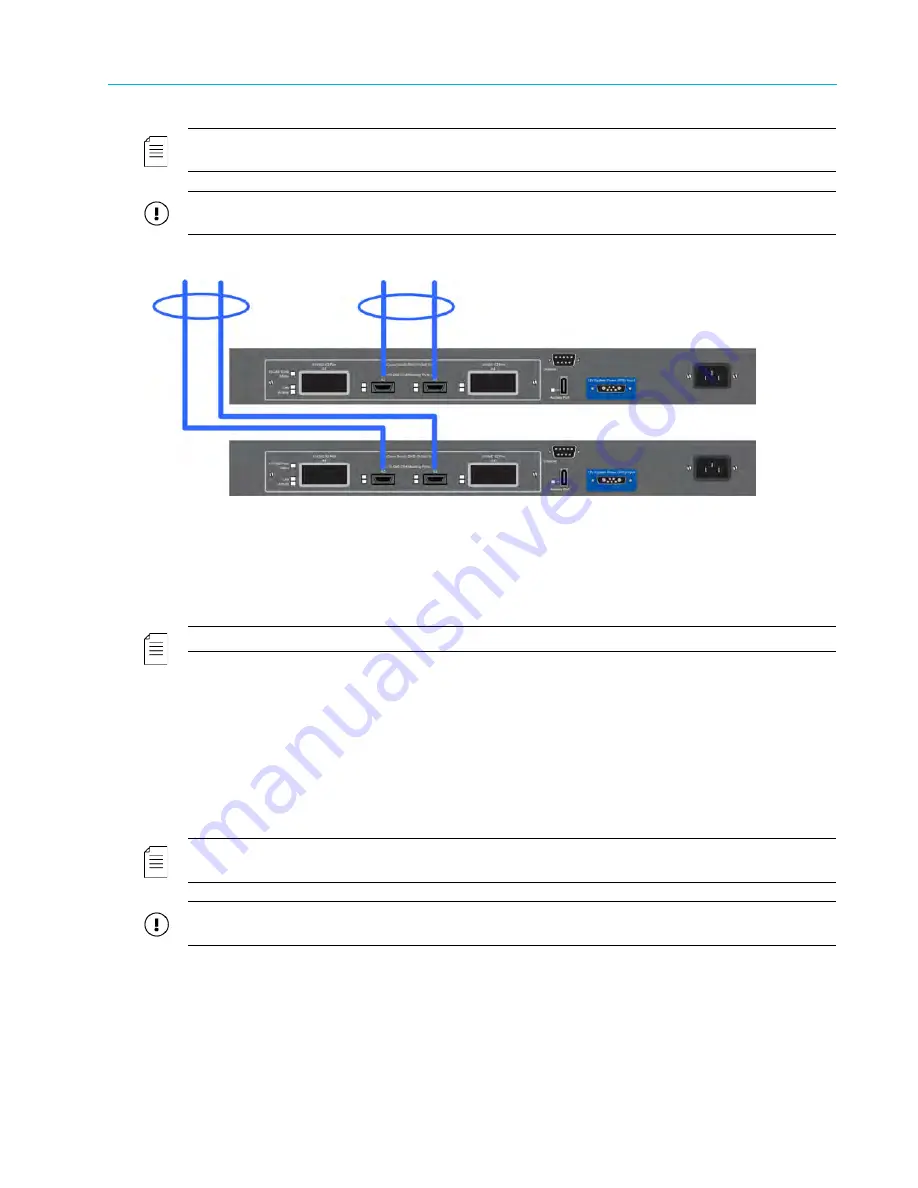
NOTE:
The switches shown in
Figure 2–25
are provided as examples only. Your switches may vary from the
ones shown.
IMPORTANT:
Make sure to use only Harmonic MediaGrid-qualified switches in your Harmonic MediaGrid
system. To find out if a switch is Harmonic MediaGrid-qualified, contact your Harmonic representative.
To Client Network
First Switch
Second Switch


