Installing the HRR 4104 Receiver
2–8
Copyright © 2005 Harmonic Inc.
2.8
Testing RF Signal Output
Once you have connected the fiber and coaxial cables, you can use the RF
monitor port to check the RF output level. The RF monitor port is a test
connector (female F-type) located on the front panel of the HRR 4104 module,
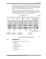
as shown in Figure 1-2 on page 1-2.
The RF monitor level is 20 dB (±1.0 dB) below the output level of the receiver.
Use the four-position selector switch on the front panel to select one of the
four receivers within the HRR 4104 module. After testing one of the receivers,
toggle the selector switch and test the next receiver. Repeat for all four
receivers.
Содержание HRR 4104
Страница 1: ...HRR 4104 Return Path Receiver Product Manual Manual Part No 700 0051981 Rev A March 2005...
Страница 8: ...Overview 1 4 Copyright 2005 Harmonic Inc...
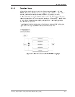
Страница 18: ...User Interface Options 3 2 Copyright 2005 Harmonic Inc Figure 3 1 HLP 4200WD Platform Main menu display...
Страница 36: ...Maintenance and Troubleshooting 5 6 Copyright 2005 Harmonic Inc...
Страница 40: ...Technical Specifications A 4 Copyright 2005 Harmonic Inc...
Страница 42: ...Harmonic Inc Offices B 2 Copyright 2005 Harmonic Inc...

