1-10 Output Stiffness
47
1
2
3
4
5
6
7
8
9
10
11
付
Ou
tlin
e
Torsional Stiffness
The speed reducer uses (1) speed ratio 50 or more for the HarmonicDrive
®
gear and (2) speed
ratio 11 for the HPF hollow shaft planetary series. The structures of the speed reducers are
different, so their rotation direction torsional stiffness are different. Refer to individual
characteristics shown on the graphs and tables.
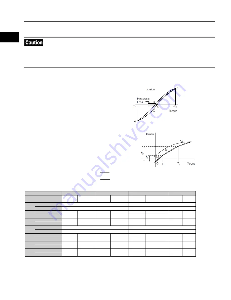
If a torque is applied to the output shaft of the actuator with the input locked, the output shaft will torsional deflect
roughly in proportion to the torque.
The upper right figure shows the torsional angle of the
output shaft when a torque, starting from zero and
increased to positive side [+T
0
] and negative side [–T
0
], is
applied to the output shaft. This [torque vs. torsional angle]
diagram, typically follows a loop of 0-A-B-A’-B’-A. The
torsional stiffness of the SHA series actuator is expressed
by the slope of this [torque vs. torsional angle diagram]
representing a spring constant (unit: Nm/rad).
As shown by lower right figure, this [torque vs. torsional
angle] diagram is divided into three regions and the spring
constants in these regions are expressed by K
1
, K
2
, and K
3
,
respectively.
K
1
:
Spring constant for torque region 0 to T
1
K
2
:
Spring constant for torque region T
1
to T
2
K
3
:
Spring constant for torque region over T
2
The torsional angle for each region is expressed as follows:
Range where torque T is T
1
or below:
Range where torque T is T
1
to T
2
:
Range where torque T is T
2
to T
3
:
The table below shows the averages of T
1
to T
3
, K
1
to K
3
, and θ
1
to θ
2
for each actuator.
Model
SHA20A
SHA25A
SHA32A
SHA40A
Reduction ratio
50:1
51:1
80:1 or
more
50:1
51:1
80:1 or
more
50:1
51:1
80:1 or more
50:1
51:1
80:1 or
more
T1
Nm
7.0
14
29
54
kgf
・
m
0.7
1.4
3.0
5.5
K1
x10
4
Nm/rad
1.3
1.6
2.5
3.1
5.4
6.7
10
13
kgf
・
m/arc min
0.38
0.47
0.74
0.92
1.6
2.0
3.0
3.8
θ
1
x10
-4
rad
5.2
4.4
5.5
4.4
5.5
4.4
5.2
4.1
arc min
1.8
1.5
1.9
1.5
1.9
1.5
1.8
1.4
T2
Nm
25
48
108
196
kgf
・
m
2.5
4.9
11
20
K2
X10
4
Nm/rad
1.8
2.5
3.4
5.0
7.8
11
14
20
kgf
・
m/arc min
0.52
0.75
1.0
1.5
2.3
3.2
4.2
6.0
θ
2
x10
-4
rad
15.4
11.3
15.7
11.1
15.7
11.6
15.4
11.1
arc min
5.3
3.9
5.4
3.8
5.4
4.0
5.3
3.8
K3
x10
4
Nm/rad
2.3
2.9
4.4
5.7
9.8
12
18
23
kgf
・
m/arc min
0.67
0.85
1.3
1.7
2.9
3.7
5.3
6.8
3
2
2
K
T
T
−
+
θ
=
ϕ
2
1
1
K
T
T
−
+
θ
=
ϕ
1
K
T
=
ϕ
angle
Torsional
*
:
ϕ
Содержание SHA CG Series
Страница 1: ...AC Servo Actuator SHA SG and CG series manual ISO14001 Hotaka plant ISO9001...
Страница 93: ...Chapter 4 Options This chapter explains the options available for the SHA series actuator 4 1 Options 94...
Страница 95: ...Options 95 1 2 3 4 Apx 6 7 8 9 10 11 Appendix Outline drawing of the actuator with an optional stand Nameplate...
Страница 100: ...Options 100 1 2 3 4 Apx 6 7 8 9 10 11 Appendix Appendix A 1 Unit conversion 101 A 2 Calculating inertia moment 103...
Страница 107: ......


