page 53
DriveCore Install DA Series Operation Manual
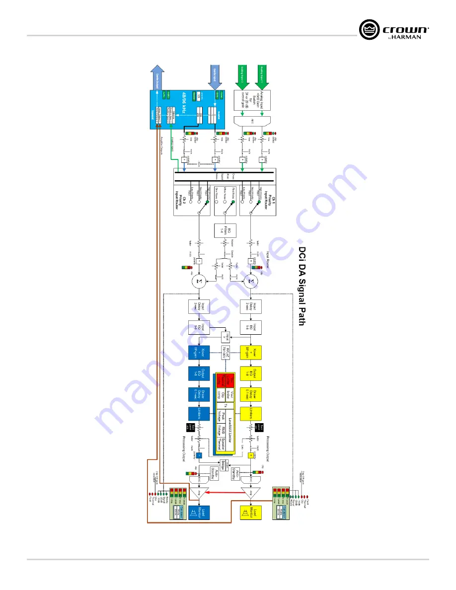
Signal Path Block Diagram
Figure 60:
Страница 1: ...provided in this manual was deemed accurate as of the publication date However updates to this information may have occurred To obtain the latest version of this manual please visit the Crown website...
Страница 2: ...eplacement of the obsolete outlet 10 Protect the power cord from being walked on or pinched particularly at plugs convenience receptacles and the point where they exit from the apparatus 11 Use only w...
Страница 3: ...ts Class B EN55103 2 2009 EMC Compatibility Product Family Standard for Audio Video Audio Visual and Entertainment Lighting Control Apparatus for Professional Use Part 2 Immunity EN 61000 3 2 2014 Lim...
Страница 4: ...Library Filename Conventions 27 Editing DSP Settings 28 Configuration Panel 29 Source Routing Panel 31 Input Output Delay 33 Input Output Equalization 34 Crossover 35 LevelMax Suite Limiters 36 Using...
Страница 5: ...th PFC for reduced current draw and industry leading efficiency Monitoring and control over TCP IP Real time continuous load monitoring Remote standby Sleep mode is activated via the Aux port Power sa...
Страница 6: ...UTION Before you begin make sure the amplifier is disconnected from the power source Figure 1 shows the dimensions of the DCi DA Series amplifiers The DCi 4 1250DA and DCi 8 600DA models are 3 5 in 8...
Страница 7: ...n the data network Dante traffic is not indicated on this LED Rear Panel Overview AUX CLASS 2 WIRING INPUT GPIO ETHERNET100Mb ACT DANTE OUT 3 3V IN PRIMARY SECONDARY CAUTION TO REDUCE THE RISK OF ELEC...
Страница 8: ...ord is disconnected from the amplifier and carefully review the total impedance for loudspeakers connected to each amplifier output If multiple loudspeakers are connected to an output in Low Z mode i...
Страница 9: ...ls to the desired level IMPORTANT Before making any wiring or installation changes turn off the amplifier and disconnect the power cord For help with determining your system s optimum gain structure s...
Страница 10: ...s a referred to as a star network topology 100Mbps network switches and Category 5 cabling can be used for smaller Dante networks where smaller channel counts and or lower sample rates are used For op...
Страница 11: ...smaller Dante networks where smaller channel counts and or lower sample rates are used For optimum performance and improved reliability a Gigabit network and Category 5e or Category 6 cabling should...
Страница 12: ...annel counts and or lower sample rates are used For optimum performance and improved reliability a Gigabit network and Category 5e or Category 6 cabling should be used Visit the Audinate website for m...
Страница 13: ...y a Gigabit network and Category 5e or Category 6 cabling should be used Visit the Audinate website for more information To provide fault protection when using Dante connect the Secondary ports of all...
Страница 14: ...arry Dante audio only and cannot be used for control and monitoring of the amplifier Launching Audio Architect After launching Audio Architect the software will scan the network for HiQnet devices and...
Страница 15: ...information regarding the PC HiQnet Address IP Address and Subnet Mask Figure 17 NetSetter window 1 PC Adapter Use this dropdown menu to select the Network Interface Card NIC that NetSetter will use...
Страница 16: ...urity measures via proxy connections 6 Static Routes This feature is used to set up a static route and connect directly to a device located on a different subnet than the PC 7 Clear Container Resets t...
Страница 17: ...ter window If a DHCP server is not detected the information will read DHCP server not detected Note that checking a device s DHCP Auto IP checkbox has no immediate effect on the column sort order NOTE...
Страница 18: ...dom HiQnet address If you want to set the HiQnet address of a device to a random ID check the Random ID checkbox If the checkbox is unchecked before applying current edits the prior HiQnet ID value wi...
Страница 19: ...ields The device is being rediscovered after applying current edits NOTE Since the sort order automatically updates when a field within the sorted column is updated the rediscovered device will occupy...
Страница 20: ...s level HiQnet address conflict etc will not be able to report its Container Position data In this instance the Container Position field will display a to indicate that the field may exist but that th...
Страница 21: ...Figure 20 NOTE When a device is added to the venue it is automatically removed from the Discovered device list If the Add discovered devices to the Venue automatically checkbox was checked upon launch...
Страница 22: ...ttings from the device s and display them in Audio Architect Matching Devices The Match Devices ribbon appears at the top of the main Audio Architect window after clicking the Go Online button from th...
Страница 23: ...prehensive diagnostics feature set All of these features can be accessed from the Configuration panel Figure 24 Configuration panel 4 channel amp model shown The DCi DA amplifiers are very capable and...
Страница 24: ...One input can be used to drive some or all of the amplifier outputs Figure 26 Use the Y checkboxes to cascade input channels Figure 27 With the Y 1 2 box checked both output Ch 1 and Ch 2 are fed by...
Страница 25: ...ured for bridge mono operation only the first odd input channel of the pair should be wired NOTE The Low Z and High Z options are still available in bridge mono mode If the amplifier outputs are confi...
Страница 26: ...h Z Low Z Operation Each amplifier output channel can be configured for high Z or low Z operation from the Amplifier Mode Settings window see Figure 30 Global Channel Specific Figure 30 Low Z High Z c...
Страница 27: ...is opens the Input Configuration panel where the amplifier input levels can be adjusted to accommodate different signal levels from the sources The meters on this panel display both peak and rms level...
Страница 28: ...aster development of third party and user tunings and libraries encouraging more people to develop custom or third party tunings Single panel access to all required tuning parameters making it easier...
Страница 29: ...dvanced Speaker Tuning panel The Advanced Speaker Tuning panel includes every parameter implemented in a speaker tuning All parameters from the Basic Speaker Tuning panel Recall Store Delete Mfr Name...
Страница 30: ...ters on the last panel closed are saved to the working library JBL Master Screen Array Library This library is included with Audio Architect at install The tunings in this library were developed and v...
Страница 31: ...dio Architect Windows XP path C Documents and Settings All Users Application Data Harman Professional Audio Architect Library Filename Conventions The file naming convention for speaker tuning librari...
Страница 32: ...eeded This drastically cuts setup time commissioning rack space and costs The DCi DA DSP can be monitored and controlled via the network using a computer running Audio Architect Some applications for...
Страница 33: ...e signal level for each channel Mute Buttons Use these buttons to mute each channel Link Buttons These buttons can be used to link the controls of channels for ganged operation Input Signal Level Mete...
Страница 34: ...fault state indicating service may be required Arrow Button Clicking this button expands or minimizes the Configuration panel window Mode Button Clicking this button opens the Amplifier Mode Settings...
Страница 35: ...the audio input from the Dante port on the back panel of the amp Each amplifier has 8 Dante input channels as well as summed variants e g Dante Inputs A B Dante Inputs C D etc Network With Analog Back...
Страница 36: ...the following additional parameters Threshold This parameter sets the level in dB below which the secondary source will be engaged Attack This parameter determines the time that it takes for the seco...
Страница 37: ...gure 40 Delay panel On Button This button turns the delay on or off Slider and Arrow Buttons Click drag this slider or click the arrow buttons at either end of the slider to adjust delay time Seconds...
Страница 38: ...eak using the Q parameter HP EQ 2nd Order 6 12dB oct filter with variable resonant peak using the Q parameter All Pass 1 90 phase shift All Pass 2 180 phase shift Frequency This field sets the center...
Страница 39: ...a single panel Filter Enable Buttons These buttons are used to enable disable the highpass and lowpass filters for the selected band Filter Type Fields These fields are used to select the filter type...
Страница 40: ...dB Note that the Advanced option must be selected to adjust these parameters manually Transducer Thermal Limiting Thermal Voltage and Thermal Response Time The transducer thermal limiter limits the lo...
Страница 41: ...imary and the other is the Secondary When using only two Dante devices the devices can be connected directly together using the Primary ports When connecting more than two devices they should be conne...
Страница 42: ...e device and indicate the following Green LEDs The green LED will light solid to indicate a network link is established and flash to indicate link activity Orange LEDs The orange LED indicates network...
Страница 43: ...l and Polarity settings located in the Input Configuration panel see Figure 44 on page 38 before being sent to the Dante network 2 Post processed audio from an amplifier output channel can be routed t...
Страница 44: ...Presets The DCi DA amplifier works with two types of presets User Presets Using Audio Architect you can create your own custom DSP presets label them and send them to the DCi DA amplifier The amp sto...
Страница 45: ...in the current venue configuration to a single file for backup and recall To save a Venue file in Audio Architect 1 In the upper left hand corner of the main Audio Architect window select the File tab...
Страница 46: ...troubleshooting purposes or by individual devices to perform certain operations Figure 47 The Event Log Viewer window The Event Log can be accessed from either the Offline ribbon Figure 48 or Online...
Страница 47: ...dditionally outputs can be controlled independently via the software Control port pinout descriptions PIN 1 Output 1 0VDC to 3 3VDC output Output impedance 1K pullup to 3 3V PIN 2 Output 2 0VDC to 3 3...
Страница 48: ...et Recalls the max preset in the high state and the min preset in the low state available only when a device preset is assigned to a control input On Value This option determines what the value of the...
Страница 49: ...table and the On Value and Off Value parameters can be toggled as desired However if a non binary SV is added the Analog Input mode becomes available In this mode the High Limit and Low Limit paramete...
Страница 50: ...does not change quickly it can take up to 60 seconds to drop offline or to recover In these modes the output is intended to be used with devices such as a backup amp switcher or an electro mechanical...
Страница 51: ...A Series Operation Manual Using the GPIO Port Figure 55 Control Port output configuration NOTE In all modes the polarity of the binary output can be toggled under the Output Polarity tab where Normal...
Страница 52: ...onfiguration and begin to output audio within 20 seconds Network communication will be re established once the network interface card boots While the amplifier is in standby the front panel Power butt...
Страница 53: ...igh Z operation AC Under Over Voltage Protection If the AC line voltage drops below 10 or rises above 10 of the nominal operating voltage of the amplifier the amplifier s power supply will turn off an...
Страница 54: ...Aux port is released When the Power button is pushed in this condition the Power Indicator will flash for 2 3 seconds CONDITION Thermal indicator is on POSSIBLE REASON The amplifier is becoming too ho...
Страница 55: ...ixer or preamp CONDITION No sound even though the amp has power Power LED is on not flashing and the amp is receiving an input sig nal Signal indicator is flashing POSSIBLE REASON Speakers not connect...
Страница 56: ...ut signal The Signal LED is not flashing even though audio is present and the channel is ready POSSIBLE REASON Input signal level is very low CONDITION Bridge LED is lit POSSIBLE REASON Amplifier is i...
Страница 57: ...page 53 DriveCore Install DA Series Operation Manual Signal Path Block Diagram Signal Path Block Diagram Figure 60 Signal Path Block Diagram...
Страница 58: ...W 600W 4 600DA 600W 1200W 1200W 1200W 1200W 4 1250DA 2500W 2500W 2500W 2500W 2500W 8 300DA 300W 600W 600W 600W 600W 8 600DA 600W 1200W 1200W 1200W 1200W Minimum Guaranteed Power 20Hz 20kHz Input Sensi...
Страница 59: ...0Hz 1000 1000 1500 1000 1000 Crosstalk below rated power 20Hz to 1kHz 80 dB Common Mode Rejection 20Hz to 1kHz typical 70 dB DC Output Offset with inputs shorted 10mV Input Impedance Nominally balance...
Страница 60: ...ower Pink Noise Typical of program material at extreme clip 4 3 2 190 650 164 1 7 185 630 159 8 5 2 205 699 176 2 6 194 664 167 16 4 9 171 583 147 2 5 168 575 145 140V 32 67 4 7 157 535 135 2 4 153 52...
Страница 61: ...ical of program material at extreme clip 4 5 6 247 844 213 2 9 235 801 202 8 9 5 298 1018 257 4 8 269 916 231 16 8 7 223 760 192 4 5 207 705 178 140V 16 8 7 230 786 198 4 5 214 730 184 200V 33 33 8 7...
Страница 62: ...of program material at extreme clip 4 19 5 533 1819 458 10 0 419 1432 361 8 17 5 384 1311 330 9 5 414 1412 356 16 17 5 365 1246 314 9 0 292 997 251 140V 8 16 8 330 1128 284 8 8 345 1176 296 200V 16 1...
Страница 63: ...program material at extreme clip 4 6 5 357 1220 308 3 3 335 1144 288 8 10 0 377 1287 324 5 2 369 1259 317 16 9 5 313 1069 269 4 8 305 1041 263 140V 32 67 9 4 296 1011 255 4 8 279 951 240 200V 66 67 9...
Страница 64: ...material at extreme clip 4 10 8 468 1597 403 5 4 445 1519 383 8 17 9 530 1810 456 9 0 476 1625 410 16 17 0 421 1437 362 8 7 389 1328 335 140V 16 17 3 439 1500 378 8 8 382 1305 329 200V 33 33 17 0 412...
Страница 65: ...ur factory within a reasonable time after receipt of the defective product at our authorized service center or our factory All expenses in remedying the defect including surface shipping costs in the...
Страница 66: ...h the defective unit to an authorized service center to obtain service They will handle the necessary paperwork and repair Remember to transport the unit in the original factory pack A list of authori...
Страница 67: ...ll carton that allows for 2 inch solid Styrofoam on all six sides of unit or 3 inches of plastic bubble wrap on all six sides of unit b Securely seal the package with an adequate carton sealing tape c...
Страница 68: ...____________________________ ________________________________________________________________________________________________________________________ __________________________________________________...
Страница 69: ......
Страница 70: ......
Страница 71: ......
Страница 72: ......