43
1
harman/kardon
Service Bulletin
Service bulletin # H/K2002-02 July 2002
Warranty labor rate: MAJOR repair
To: All harman/kardon Service Centers
Model: DVD50
Subject: Faulty 23 Pin Flat Cable
In the event you receive a DVD50 with the complaint “After loading a disc, a message appears in the
display, or on the television: ‘
Disc Error’
or
‘Disk incompatible, please insert compatible disk’
or
‘This
Disc in incompatible with the unit’,
”:
First attempt a playback of a different CD or DVD disc, to assure the problem is not with a particular disc. If
the same error messages are still observed, inspect and and replace the 23 Pin Flat ribbon cable that
attaches the Laser Assembly Connector to the Laser Module.
CAUTION:
Electronic parts are susceptible to static electricity and may easily damaged; take a proper grounding
treatment as required.
Take care to separate and identify the various screws; many different types of screws are used in the unit, and parts can
be damaged by insertion of the wrong screws. Use of a magnetized screw driver is recommended.
1) Remove the (7) top cover screws, remove the cover.
2) Unplug the shielded 18 conductor flat ribbon cable stretching across the top of the unit connecting the
main PCB with the front panel, at the Main PCB.
3) Unplug all three Orange-colored Molex connectors (two larger P3102/P3101 and one smaller P4901) from
the Main PCB.
4) Outside the unit, remove all Phillips screws visible on the rear panel.
5) Remove (3) Phillips screws on the main support bracket.
6) Unplug the flat ribbon cables at connectors PMD02 & PMD03 on the Main PCB.
7) Lift and remove entire support bracket with Main and Output PCB’s attached, and set it outside the unit.
8) Remove three Phillips screws holding the plastic clamp; lift and remove clamp.
9) Remove the single Phillips screw in the middle of the 5-tray disc. Lift and remove the disc; it must be
manipulated to clear two plastic tabs at the rear of the tray base.
10) Detach the rear panel from the unit; there are two tabs/catches on both sides that need to be released.
Each tab may have to be bent slightly with a flat-blade screwdriver to release it. Pull the power cord’s
grommet out of the slot in the rear panel to detach it completely from the unit.
11) The laser PCB, in the area directly below the laser lens has two pairs of small, D-shaped solder pads.
(See illustration) Temporarily solder-bridge each pair together to assure ESD damage to the laser diode
does not occur.
12) Remove the (4) small plated screws from the top of the Laser assembly.
13) Carefully lift the Laser assembly partially up and out of the unit; it will be attached by the 23 pin flat ribbon
cable and a smaller 8 conductor flat ribbon cable on one side.
14) Inspect the 23 pin cable; if the length is 2 3/8” (60mm), or it’s “creased”, replace it with
h/k part# 6850R-JW14Z – this is a 5 ½” (140mm) cable.
15) Reassemble the unit in reverse order, taking care to replace all cable connections and use correct original
screws in their proper locations. Be sure to thoroughly desolder the shorting pads on the laser PCB.
16) Test the unit.
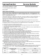
Model
Serial Number (120v)
Status
Action
DVD50
LG0007-01000
to
LG0007-07600
23 Pin Flat Ribbon Cable May Be
Faulty
Replace 2 3/8” (60mm)
with 5 ½” (140mm) part
DVD50
LG0007-07601 and above
Modified by Factory
None Required


