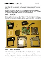
¡
™
£
¢
∞
§
¶
•
ª
‚
⁄
¤
¡
Play (CDP)-Deck Analog Output
™
Record (CDR)-Deck Analog Output
£
Record (CDR)-Deck Analog Input
¢
Play (CDP)-Deck Coaxial-Digital Output
∞
Record (CDR)-Deck Coaxial-Digital Output
§
Record (CDR)-Deck Coaxial-Digital Input
¶
Record (CDR)-Deck Optical-Digital Input
•
Record (CDR)-Deck Optical-Digital Output
ª
Play (CDP)-Deck Optical-Digital Output
‚
Remote IR Input
⁄
Remote IR Output
¤
AC Power Cord
¡
Play (CDP)-Deck Analog Output:
These
jacks carry the analog audio output signal from
the
Play Deck
3
. Connect them to the CD
input jacks on a receiver, preamp or processor.
™
Record (CDR)-Deck Analog Output:
These jacks carry the output signal from the
Record Deck
%
. Connect them to the Tape
Play/In input jacks on a receiver, preamp or
processor.
£
Record (CDR)-Deck Analog Input:
These
jacks accept the analog signals that are used
for CD recordings. Connect them to the Tape
Rec/Play outputs on a receiver, preamp or
processor.
¢
Play (CDP)-Deck Coaxial-Digital
Output:
This jack carries the digital-audio out-
put signal from the
Play Deck
3
. Connect it
to a coaxial-digital input on a receiver, proces-
sor or digital decoder.
∞
Record (CDR)-Deck Coaxial-Digital
Output:
This jack carries the digital audio out-
put signal from the
Record Deck
%
. Connect
it to a coaxial digital input on a receiver,
processor or digital decoder.
§
Record (CDR)-Deck Coaxial-Digital
Input:
This jack accepts the digital-audio input
signal from a compatible digital audio product
and should be connected directly to a digital
player or to a coaxial-digital output on a CD or
DVD player or an A/V receiver or processor.
IMPORTANT NOTE:
The coaxial digital inputs
should only be connected to
digital
input or
output jacks. Even though they use the same
RCA-type connector as standard analog audio
connections, DO NOT connect them to conven-
tional analog input or output jacks.
¶
Record (CDR)-Deck Optical-Digital
Input:
This jack accepts the digital-audio input
signal from a compatible digital audio product,
and should be connected directly to the optical-
digital output on a CD or DVD player or an A/V
receiver or processor.
•
Record (CDR)-Deck Optical-Digital
Output:
This jack carries the digital audio out-
put signal from the
Record Deck
%
. Connect
it to an optical digital input on a receiver,
processor or digital decoder.
ª
Play (CDP)-Deck Optical-Digital
Output:
This jack carries the digital audio out-
put signal from the
Play Deck
3
. Connect it
to an optical-digital input on a receiver, proces-
sor or digital decoder.
‚
Remote IR Input:
Connect the output of a
remote infrared sensor or the remote control
output of another compatible Harman Kardon
product to this jack. This will enable the remote
control to operate even when the front panel
Remote Sensor
¯
is blocked. This jack may
also be used with compatible IR remote control
based automation systems.
⁄
Remote IR Output:
Connect this jack
to the IR input jack of another compatible
Harman Kardon remote controlled product to
have the built-in
Remote Sensor
¯
on the
CDR 30 provide IR signals to other compatible
products.
¤
AC Power Cord:
Connect this plug to an
AC outlet. If the outlet is switch controlled,
make certain that it is in the
ON
position.
Rear Panel Connections
CDR30
harman/kardon
10
Содержание CDR 30
Страница 19: ...IC501 2 8 IC502 CDR30 harman kardon 19 ...
Страница 62: ...CDR30 harman kardon 62 ...
Страница 63: ...CDR30 harman kardon 63 ...
Страница 64: ...CDR30 harman kardon 64 ...
Страница 65: ...CDR30 harman kardon 65 ...
Страница 66: ...CDR30 harman kardon 66 ...
Страница 67: ...CDR30 harman kardon 67 ...
Страница 68: ...CDR30 harman kardon 68 ...
Страница 69: ...CDR30 harman kardon 69 ...
Страница 70: ...CDR30 harman kardon 70 ...
Страница 71: ...CIRCUIT DIAGRAMS 1 POWER SMPS CIRCUIT DIAGRAM 00 11 10 SI2448 UL CDR30 harman kardon 71 ...
Страница 72: ...2 CD PLAY CIRCUIT DIAGRAM CDR30 harman kardon 72 ...
Страница 73: ... 38 2 CD PLAY CIRCUIT DIAGRAM 73 Part 1 ...
Страница 74: ... 38 2 CD PLAY CIRCUIT DIAGRAM 74 CD PLAY CIRCUIT DIAGRAM Part 2 ...
Страница 75: ...3 CD RECORD 1 CIRCUIT DIAGRAM CDR30 harman kardon 75 ...
Страница 76: ... 39 3 CD RECORD 1 CIRCUIT DIAGRAM 76 Part 1 ...
Страница 77: ... 39 3 CD RECORD 1 CIRCUIT DIAGRAM 77 CD RECORD CIRCUIT DIAGRAM Part 2 ...
Страница 78: ...4 CD RECORD 2 CIRCUIT DIAGRAM CDR30 harman kardon 78 ...
Страница 79: ... 40 4 CD RECORD 2 CIRCUIT DIAGRAM 79 Part 3 ...
Страница 80: ... 40 4 CD RECORD 2 CIRCUIT DIAGRAM 80 CD RECORD CIRCUIT DIAGRAM Part 4 ...
Страница 81: ...5 CD RECORD 3 CIRCUIT DIAGRAM CDR30 harman kardon 81 ...
Страница 82: ... 41 5 CD RECORD 3 CIRCUIT DIAGRAM 82 Part 5 ...
Страница 83: ... 41 5 CD RECORD 3 CIRCUIT DIAGRAM 83 CD RECORD CIRCUIT DIAGRAM Part 6 ...
Страница 84: ...6 I O CIRCUIT DIAGRAM CDR30 harman kardon 84 ...
Страница 85: ... 42 6 I O CIRCUIT DIAGRAM 85 Part 1 ...
Страница 86: ... 42 6 I O CIRCUIT DIAGRAM 86 I O CIRCUIT DIAGRAM Part 2 ...
Страница 87: ... 43 7 TIMER CIRCUIT DIAGRAM CDR30 harman kardon 87 ...


