3 - Description
3.14
ATTENTION! Always tilt up the ladder before driving.
The hydraulic support leg is driven by a seperate hydraulic outlet on
the tractor. The support leg is stored in its retracted position when
the sprayer is attached to the tractor.
To retract the support leg: Start with unlocking the leg at the secu-
ring grip placed on the sprayer. Then use the tractor’s hydraulic lever
to raise or lower the support leg. After raising or lowering the sup-
port leg it should be secured by turning the grip on the sprayer to
locked position.
The actual tank level in the main tank can be observed on the tank
level indicator. The scale is displayed in litres or Imp. gal/US gal. (cer-
tain countries).
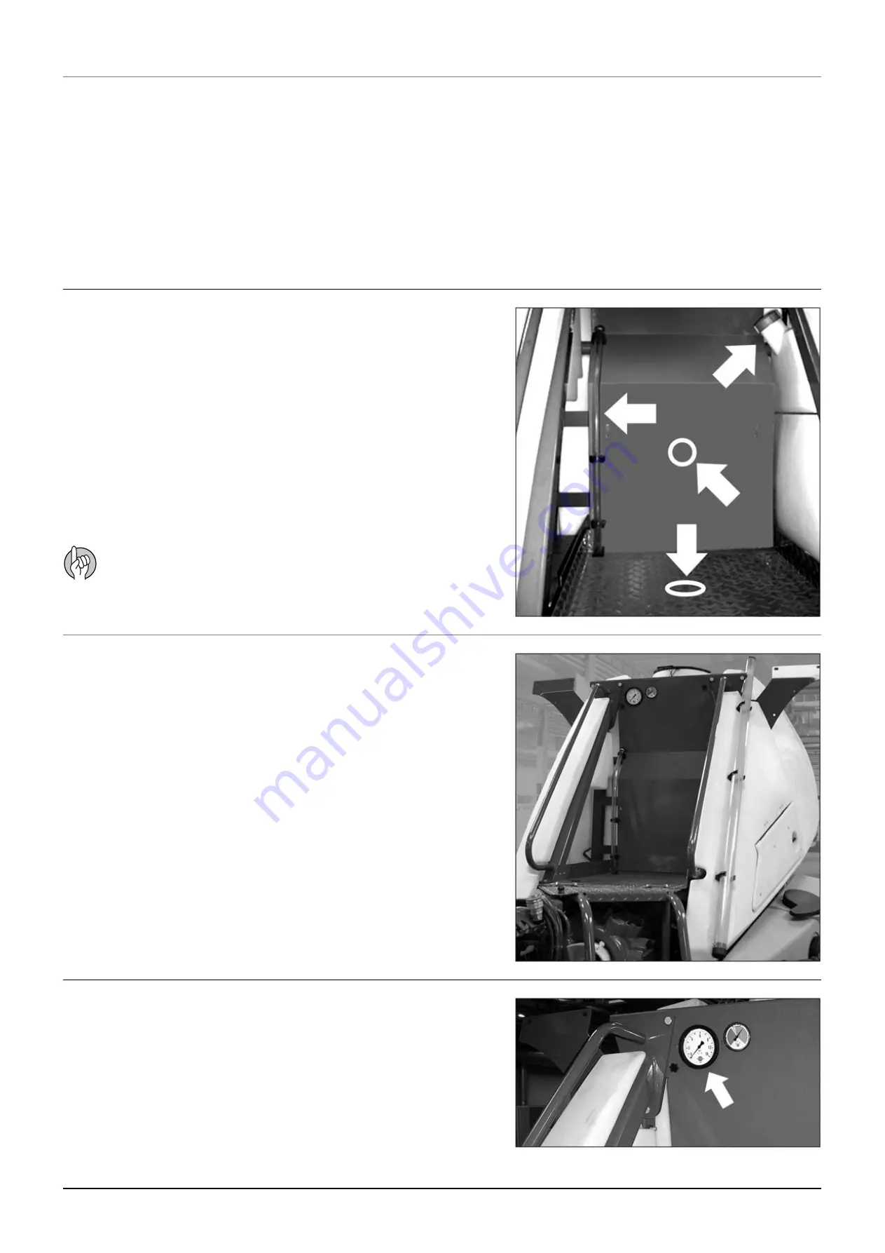
The remote pressure gauge is integrated in the platform. This gauge
measures the working pressure in the boom tubes as close to the
nozzles as possible.
The outputs stated in the nozzle charts are always based on the
pressure measured at the nozzle. Always adjust pressure when cali-
brating and spraying according to readings at the remote pressure
gauge.
To get access to the platform pull and tilt the ladder down. In retrac-
ted position the ladder is secured by a rubber stop.
Hydraulic, electric and MANIFOLD components are situated under-
neath the platform floor. By lifting the platform floor, these compo-
nents are accessible. Also the clean water tank is integrated to the
side of the platform.
The platform gives access to the clean water tank lid, the main tank
lid. Electrics, fast filler is situated behind the cover located at the side
facing to the main tank. At the same side the pressure gauge and
level indicator for the rinsing tank are visible.
Remote pressure gauge
Tank level indicator
Platform
Hydraulic support leg (COMMANDER 6600 only)
Содержание COMMANDER TWIN FORCE 3200
Страница 1: ...COMMANDER TWIN FORCE www hardi international com 67000200 Version 1 03 GB 06 2007 Instruction book ...
Страница 8: ...Table of contents TOC 6 ...
Страница 10: ...1 CE Declaration 1 2 ...
Страница 14: ...2 Safety notes 2 4 ...
Страница 66: ...6 Maintenance 6 2 Boom lubrication oiling plan 32 36 m ...
Страница 67: ...6 Maintenance 6 3 Trailer lubrication oiling plan ...
Страница 107: ...8 Technical specifications 8 11 Charts Boom hydraulic Y Boom hydraulic Z ...
Страница 108: ...8 Technical specifications 8 12 Sprayer hydraulic Fan transmission ...
Страница 109: ...8 Technical specifications 8 13 Electrical specifications for boom and work light ...
Страница 110: ...8 Technical specifications 8 14 ...


