ASSEMBLY INSTRUCTIONS (Continued)
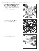
4. Route wires and support cable through canopy
screw cover (F) and canopy (E) and position
them on the downrod. (Fig. 4)
Hardware Used
DD
x 1
Nylon Lock
Nut
FF
x 1
Socket
Head
Cap Screw
E
D
F
4
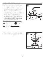
3. Route the black, white and blue wires through
the downrod. Push the downrod into top of
center support housing of the motor arm
assembly (A) until the downrod makes contact
with the stop feature. Align holes in downrod
with holes in support housing. Using the
T-handle wrench (J), secure downrod to fan
assembly with socket head cap screw (FF)
and nylon lock nut (DD). NOTE: MAKE SURE
SCREW PASSES THROUGH HOLES IN
DOWNROD BY PULLING UP ON THE
DOWNROD PRIOR TO FULLY TIGHTENING
THE CAP SCREW. Fully tighten all three
screws preassembled on the support housing
of the motor arm assembly (A). (Fig. 3)
A
DD
FF
3
D
J
8


