background image

Figura 109

Figura 110

Figura 111

334  

HANDICARE 2000 SIMPLICITY / STYLE MANUALE DI INSTALLAZIONE

Telecomandi

Telecomandi

Articoli necessari: 

Utensili necessari: 

• Telecomandi 

• N° 2 viti

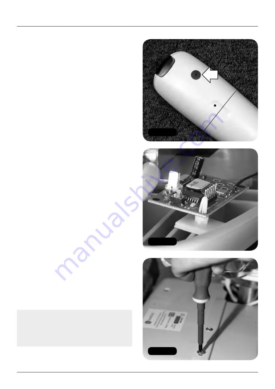
I montascale della serie 2000 devono essere forniti 
con telecomandi a infrarossi o a radio frequenza, in 
funzione dei requisiti d’installazione. Il telecomando 
a infrarossi ha un coperchietto dipswitch rosso sul 
retro, mentre il telecomando a radio frequenza ha 
un coperchietto dipswitch verde sul retro 

(Figura 

109)

. Se non sapete ancora quale tipo di sistema 

di telecomando avete montato, fate riferimento al 
disegno oppure rimuovete il sottopiatto dell’unità e 
verificate se vedete se è presente un ricevitore radio 

(Figura 110)

.

Programmazione

I telecomandi a infrarossi forniti con il montascale 
devono essere pronti all’uso, appena estratti 
dalla sua confezione. Se il montascale non sale o 
scende le scale quando vengono premuti i pulsanti 
corrispondenti, o se sono presenti altri montascale 
nelle vicinanze, seguite la procedura illustrata qui  
di seguito.


1

   Rimuovere il coperchio dall’unità di alimentazione 

(Figura 111)

.


2

   Portare entrambi i telecomandi vicino al 

montascale e poi programmate il telecomando 
nel seguente modo.


a

  Per applicazioni con montascale singolo:


i

   Premere e tenere premuto il pulsante rosso 

sul PCB 

(Figura 112)

 – si accenderà in 

LED giallo sul PCB.


ii

   Premere qualsiasi pulsante sul telecomando 

e la luce gialla si spegnerà.


iii

  La programmazione è terminata.

Nota: 

l’illuminazione a basso consumo 

energetico può interferire con il segnale 
a infrarossi, facendo fermare o avviare il 
montascale. Riprogrammare i telecomandi con  
le luci accese può risolvere questo problema.

Содержание 2000 SIMPLICITY

Страница 1: ...000411 1003 HANDICARE 2000 SIMPLICITY STYLE INSTALLATION MANUAL INSTALLATIEHANDLEIDING INSTALLATIONSANLEITUNG MANUEL D INSTALLATION MANUAL DE INSTALACI N MANUALE DI INSTALLAZIONE...

Страница 2: ...ix 4 for further details 2 Installation tools required Handicare 2000 Simplicity Style installation manual Issue No of this manual is 0416 1 ORIGINAL LANGUAGE ENGLISH Loading toggle Loading bars Short...

Страница 3: ...9 B 158 4 L X W 28 GD R665 12 2 151 1660 658 B 157 5 W B 31 S 341 13 3 52 572 654 B 153 C 6 B B 65 HL14 25 R447 N 14 3 105 1155 648 B 147 D 7 F B X 10 GI R596 15 4 16 615 B 114 8 L X B 44 S 484 16 5 3...

Страница 4: ...on or hazard Note See Appendix 3 for hinge track settings 1 The hinge track section must be installed before the rest of the track a Position the hinge track section in to the feet with the back of ea...

Страница 5: ...k format checked By Swivel Bracket NO Brace Bar 1 UnderFloor Lower 0 UnderFloor Standard 0 Parts for Build Product type RTC 2000 Figure 5 Figure 4 HANDICARE 2000 SIMPLICITY STYLE INSTALLATION MANUAL 5...

Страница 6: ...section before the first joint to the correct height Figure 6 Tighten the lock bolt to 45Nm Figure 7 3 Attach the top rail on to the two stanchions Use stanchion rail bolts supplied Figure 8 Note See...

Страница 7: ...hions without adjusting the height 6 Add all of the track bolts These should be hand tightened to a torque of 25Nm Figure 10 7 Check all stanchion heights and tighten the stanchions Figure 11 Note For...

Страница 8: ...f the stanchion f Insulate the connector block behind the comms contact and then push it into the track g Connect the two grey cables that are protruding from the top of the stanchion with a connector...

Страница 9: ...ENGLISH Figure 12 Figure 13 Figure 14 Figure 15 Figure 16 Figure 17 Track electrical connections HANDICARE 2000 SIMPLICITY STYLE INSTALLATION MANUAL 9...

Страница 10: ...en the power supply cable to the back of the stanchion as shown in Figure 22 i Connect the power supply cable and negative charge connection loom to the two connector block Figure 23 j Wrap the two re...

Страница 11: ...ENGLISH Figure 23 Figure 21 Figure 22 Figure 26 Figure 24 Figure 25 Track electrical connections HANDICARE 2000 SIMPLICITY STYLE INSTALLATION MANUAL 11...

Страница 12: ...ke off the front cover from the power unit 5 Assemble the footplate footplate accessories kit Manual gas strut footplate a Remove the footrest assembly from the footrest kit box Loosen the screw and r...

Страница 13: ...ENGLISH Figure 30 Figure 31 Figure 32 Figure 34 Figure 35 Figure 33 HANDICARE 2000 SIMPLICITY STYLE INSTALLATION MANUAL 13 Power pack and footplate...

Страница 14: ...ay connector Part No 181001 50083 and conversion loom SIM22900 seat direction key switch and swivel can only be fitted one way Figure 41 b 2 5mm battery link Part No 181001 52036 across the flying bat...

Страница 15: ...ENGLISH Figure 39 Figure 40 Figure 41 Figure 42 Figure 43 Figure 44 HANDICARE 2000 SIMPLICITY STYLE INSTALLATION MANUAL 15 Power pack and footplate...

Страница 16: ...TION MANUAL Power pack and footplate 9 When the power pack is fully and correctly engaged with the rack remove the loading bars from the track Figure 45 10 Remove the dummy seat toggle looms 11 Refit...

Страница 17: ...n speed it up as it exits the bend a Position the magnets on the bottom track Figures 47 and 48 b Drive the lift from the bottom of the track up the stairs The lift should slow down as it enters the b...

Страница 18: ...ase bolt and washer Figure 52 4 Lift the seat and position it on to the seat stem Figure 53 Note Be careful not to knock the swivel safety switch when lowering the seat onto the stem Figure 54 5 Gentl...

Страница 19: ...ENGLISH Figure 56 Figure 55 Figure 53 Figure 54 HANDICARE 2000 SIMPLICITY STYLE INSTALLATION MANUAL 19 Fitting the 2000 Simplicity seat manual...

Страница 20: ...re 58 20 HANDICARE 2000 SIMPLICITY STYLE INSTALLATION MANUAL Fitting the 2000 Simplicity seat manual 10 Fit the earth cable to the top of the seat plate Figure 57 11 Fit the plastic cap to the seat fr...

Страница 21: ...ct the diagnostic display red black and yellow c Connect the key switch loom from the power pack orange and green to the swivel switch loom connector 2 x white Figure 59 d Connect the seat to the swiv...

Страница 22: ...manual 2 Connect the earthing terminal black to the pack and secure with the nut Figures 63 and 64 3 Connect the main seat loom brown and pink to the chassis loom red and pink two black connectors Fig...

Страница 23: ...Tools required Seat 13mm Socket 4mm Allen key No 2 Pozi drive 1 Remove the seat stem from the packaging Figure 67 2 Attach the seat stem to the chassis Figure 68 3 When lowering the seat onto the stem...

Страница 24: ...eat base bolt and washer Figure 72 8 Swivel the seat back to the drive position using the swivel levers 9 Remove the drive toggle and link cables and make the seat cable connections by feeding through...

Страница 25: ...ENGLISH Figure 75 Figure 76 HANDICARE 2000 SIMPLICITY STYLE INSTALLATION MANUAL 25 Fitting the Style seat manual...

Страница 26: ...eat to the swivel switch loom connector white Figure 78 e Connect the toggle loom orange blue and green Figure 79 f Connect the infra red receivers on the left and right sides of the pack blue sleeved...

Страница 27: ...ENGLISH Figure 80 Figure 84 Figure 83 Figure 82 Figure 81 HANDICARE 2000 SIMPLICITY STYLE INSTALLATION MANUAL 27 Electrical connections Style seat manual...

Страница 28: ...2 Attach the seat stem to the chassis Figure 86 3 When lowering the seat onto the stem ensure the seat is in the ride position and the seat switch roller does not get damaged by the switch cam Figure...

Страница 29: ...ENGLISH Figure 89 Figure 91 Figure 90 Figure 92 HANDICARE 2000 SIMPLICITY STYLE INSTALLATION MANUAL 29 Fitting the Style seat powered...

Страница 30: ...arth stud Figure 96 5 Connect the manual swivel over ride loom to the motor loom 4 x Green 5 Figure 97 6 Connect the manual swivel over ride loom earth to the chassis earth stud Figure 98 7 Seat Loom...

Страница 31: ...ENGLISH Figure 96 Figure 98 Figure 97 Figure 99 Figure 100 Figure 101 HANDICARE 2000 SIMPLICITY STYLE INSTALLATION MANUAL 31 Electrical connections Style seat powered...

Страница 32: ...earthing terminal black to the pack and secure with the nut Figures 104 and 105 10 Connect the main seat loom brown and pink to the chassis loom red and pink two black connectors Figure 106 11 Test th...

Страница 33: ...ENGLISH Figure 107 Figure 108 Figure 106 HANDICARE 2000 SIMPLICITY STYLE INSTALLATION MANUAL 33 Electrical connections Style seat powered...

Страница 34: ...board has been fitted Figure 110 Programming The infra red remote control handsets supplied with the lift should work out of the box If the lift does not travel up and down the stairs when the corres...

Страница 35: ...109 ii Set the dipswitches on the PCB on both handsets to the same settings note that the next pair of handsets will require the dipswitches to be set to a different combination Figure 113 iii Press...

Страница 36: ...the up and down button on each and checking that the lift moves in the corresponding direction Note If a second stairlift using RF handsets is fitted in close proximity to the first the dipswitches o...

Страница 37: ...k from where the lift has stopped The repeater does not require line of sight so can be placed discreetly for example behind the track 4 After turning off the power to the system wire the RF repeater...

Страница 38: ...rs to ensure that it will not encounter any unforeseen obstacles Note Look for any other potential obstacles such as window ledges or exposed pipework that could obstruct the movement of the lift at t...

Страница 39: ...switch operation a Turn the key to the off position and ensure that the lift will not drive 0 should show in the diagnostic display when you try to drive the lift with the key switch in the off posit...

Страница 40: ...e lift should stop 7 Check the swivel interlock Figure 121 a Drive the lift in the up direction b Swivel the seat the lift should stop c Drive the lift in the down direction d Swivel the seat the lift...

Страница 41: ...ttom of the track d Depress the up button and keep it depressed e Observe the function of the lift The lift should i Drive up the stairs ii Stop at the park position iii Beep whilst raising the hinge...

Страница 42: ...h the stairlift The stairlift will still charge with the keyswitch disabled On off switch DO NOT turn the stairlift off using this switch unless you will not be using the stairlift for a prolonged per...

Страница 43: ...f fitted How to operate the hinge section using the lift toggle control How to operate the hinge section using the handsets The lift beeps before and whilst the hinge operates to warn the client that...

Страница 44: ...stairlift in operation Your stairlift is fitted with sensitive side edges and undertray on the footplate which will automatically stop the stairlift if it detects any obstructions NEVER use the stair...

Страница 45: ...e lift 2 Lubricate the swivel mechanism with a small quantity of petroleum jelly a Remove the seat by unscrewing the retaining bolt Figure 123 b Apply lubricant to the nylon washer c Refit the seat an...

Страница 46: ...stop Right hand Bottom stop Left hand Description End limits activated Telephone fault finding action Ask client to tap trunnion guards in case they are stuck If this does not correct the fault send...

Страница 47: ...gineer On site fault finding action Drive lift to charge contacts Check charging circuit if Okay code not displayed If lift will not drive replace batteries and check charging circuit Code Meaning 8 8...

Страница 48: ...ite fault finding action Replace main board Code Meaning n Half speed Description Telephone fault finding action Send engineer if permanently showing On site fault finding action Check reed switches a...

Страница 49: ...tware and later only Description Faulty power supply Telephone fault finding action Send engineer On site fault finding action Replace power supply Code Meaning y Software error Description The main c...

Страница 50: ...WN RED RED RED YELLOW TAG RED TAG RED TAG ORANGE UP LIMIT UP LIMIT YELLOW DOWN LIMIT DOWN LIMIT YELLOW WHITE PINK WHITE SPADE SPADE SPADE FINAL LIMIT HINGE FUSED AV OUTPUT AV OUTPUT BLK WHT STRIPE SW...

Страница 51: ...ELLOW TAG RED TAG RED TAG ORANGE DOWN LIMIT DOWN LIMIT YELLOW UP LIMIT UP LIMIT YELLOW WHITE PINK WHITE SPADE SPADE SPADE FINAL LIMIT HINGE FUSED AV OUTPUT AV OUTPUT BLK WHT STRIPE SW 0V HINGE DATA GR...

Страница 52: ...S INTO ON OFF ROCKER SWITCH ON FRONT PANEL SWIVEL MOTOR NOTE THERE ARE NO END LIMITS ON THE POWER SWIVEL FROM HAN201 PCB DIP SWITCH NEGATIVE GREY ENSURE JUMPER IS PRESENT ON CONNECTOR M1 M2 ON 1 2 3 4...

Страница 53: ...OTOR CONNECTIONS BLUE M2 BROWN M1 SWITCH MOUNTING BRACKET SW7 SW6 SW3 SW5 SW4 SW2 SW1 SW8 YELLOW YELLOW BLACK BLACK INTERLOCK SWITCH ON DOWNSIDE ARM ONLY ORANGE BLUE LOOP GREEN BLUE 1 2 1 2 1 2 1 2 NO...

Страница 54: ...UIT FULL SPEED INTERNAL CURVE CONNS WHEN LOOM 181001 50062 IS PLUGGED INTO THE 4 WAY CONNECTOR 2 ORANGE 2 RED WIRES WILL BE AVAILABLE TO CONNECT INTO TRACK SECTION UPSTAIRS RED CHARGE CONTACT NOTE ON...

Страница 55: ...CHARGE CONTACTS GREY GREY GREY BULLET CONNECTOR 1 1 RED RED GREY RED INTERMEDIATE CHARGE CONTACTS POSITIVE COMMS POSITIVE COMMS 0V 33VDC OPTIONAL OBJECT DETECTOR SENSOR INPUT M1 M2 SPEED ADJUSTMENT HI...

Страница 56: ...2000 DIP SETTINGS LH STANDARD 4 3 2 1 4 3 2 1 1 2 3 4 1 2 3 4 N O N O FUNCTION OF SWITCHES IF ANY DIP SWITCHES ARE CHANGED PLEASE TURN OFF LIFT WAIT 10 SECONDS THEN POWER THE LIFT BACK ON INFRARED RAD...

Страница 57: ...LH INTERNAL BEND DIP 1 DIP 2 4 3 2 1 4 3 2 1 1 2 3 4 1 2 3 4 N O N O FUNCTION OF SWITCHES IF ANY DIP SWITCHES ARE CHANGED PLEASE TURN OFF LIFT WAIT 10 SECONDS THEN POWER THE LIFT BACK ON INFRARED RADI...

Страница 58: ...AULT OFF DIP 1 DIP 2 5A QUICK BLOW BATTERY POSITIVE CHARGE AUDIO VISUAL CONNECTOR BRAKE CONNECTOR INFRARED RADIO LEARN BUTTON IF ANY DIP SWITCHES ARE CHANGED PLEASE TURN OFF LIFT WAIT 10 SECONDS THEN...

Страница 59: ...sion ALL DIMENSIONS IN MM UNLESS OTHERWISE STATED rtc 91602 Kamaldeep Bilkhu 18 03 15 Light Grey RIGHT Companion Stairlifts rtc 91602 REV COMMENTS A 1st Issue BY DATE Track Bolts 22 Fitting Kit Joinin...

Страница 60: ...EFERENCE SMITH56033 PG NUMBER Hand of Rail Rail Colour DRAWING NUMBER Light Grey RIGHT rtc 91602 Track Bolts 22 Fitting Kit Joining plugs 12 Additional Charge Points section by stanchion Charge Points...

Страница 61: ...NGTH SB No UF RAIL TOOTH DISTANCE LENGTH TYPE SETTING HT 1 GROUND FLOOR 16 2 1 11 395 A 74 A 2 B W 28 S 308 17 2 24 264 470 A 149 3 W W 48 HR17 R159 N 18 4 4 649 B 127 4 F W X 37 GI R596 19 5 26 286 6...

Страница 62: ...Kortsluitingskoppelstukken Moersleutel van 8 mm Moersleutel van 13 mm Moersleutel van 17 mm Kruiskopschroevendraaier nr 2 en nr 3 Nylon schoonmaakkoord voor elektriciens minimaal de lengte van de rai...

Страница 63: ...5 W B 31 S 341 13 3 52 572 654 B 153 C 6 B B 65 HL14 25 R447 N 14 3 105 1155 648 B 147 D 7 F B X 10 GI R596 15 4 16 615 B 114 8 L X B 44 S 484 16 5 30 330 541 B 13 TOTAAL 5168 17 6 30 619 B 118 18 7...

Страница 64: ...erd voordat u de rest van de rails aanbrengt a Plaat het schuifrailsgedeelte in de poten met de achterkant van elke poot op een afstand van 60 mm van de dwarsbalk of de rand van een eventuele obstruct...

Страница 65: ...oestemming dezer GETEKEND mark staniland DATUM Contract klant Handicare Stairlifts Ltd REFERENTIE R D positie 5 TEKENINGNUMMER PG NUMMER Verbindings stukken Tanden HOOGTE INSTELLEN Afb 5 Nr Pootnummer...

Страница 66: ...de juiste hoogte Afbeelding 6 Draai de vergrendelingsbout vast tot 45 Nm Afbeelding 7 3 Bevestig de bovenste rail aan de twee stutten Gebruik de meegeleverde stut railbouten Afbeelding 8 Opmerking Zi...

Страница 67: ...en 6 Voeg alle railsbouten toe Deze bouten moeten met de hand worden vastgemaakt tot een aanhaalmoment van 25 Nm Afbeelding 10 7 Controleer de hoogte van alle stutten en maak de stutten vast Afbeeldin...

Страница 68: ...ovenkant van de stut weer naar buiten f Isoleer het aansluitblok achter het comms contactpunt en duw dit dan weer terug in de rails g Sluit de twee grijze kabels die aan de bovenkant van de stut naar...

Страница 69: ...NEDERLANDS Elektrische aansluitingen INSTALLATIEHANDLEIDING VOOR DE HANDICARE 2000 SIMPLICITY STYLE 69 Afb 12 Afb 13 Afb 14 Afb 15 Afb 16 Afb 17...

Страница 70: ...n goed vast op de achterkant van de stut zoals weergegeven in Afbeelding 22 i Sluit de netvoedingskabel en negatieve laadaansluitingsbundel aan op het dubbele aansluitblok Afbeelding 23 j Wikkel de tw...

Страница 71: ...Afb 23 Afb 21 Afb 22 Afb 26 Afb 24 Afb 25 NEDERLANDS Elektrische aansluitingen INSTALLATIEHANDLEIDING VOOR DE HANDICARE 2000 SIMPLICITY STYLE 71...

Страница 72: ...4 Verwijder de voorste afdekking van de voedingseenheid 5 Zet de voetplaat in elkaar pakket met voetplaataccessoires Handmatige voetplaat met gasstang a Verwijder de voetsteunassemblage uit het pakket...

Страница 73: ...Afb 30 Afb 31 Afb 32 Afb 34 Afb 35 Afb 33 INSTALLATIEHANDLEIDING VOOR DE HANDICARE 2000 SIMPLICITY STYLE 73 NEDERLANDS Voedingsblok en voetplaat...

Страница 74: ...en pakket met voetplaataccessoires Afbeelding 40 7 Sluit de testbundels op de tuimelschakelaar van de stoel aan a 8 wegs aansluiting van de aandrijvingsschakelaar onderdeelnr 181001 50083 en conversie...

Страница 75: ...Afb 39 Afb 40 Afb 41 Afb 42 Afb 43 Afb 44 INSTALLATIEHANDLEIDING VOOR DE HANDICARE 2000 SIMPLICITY STYLE 75 NEDERLANDS Voedingsblok en voetplaat...

Страница 76: ...aan het voedingsblok Afbeelding 44 geeft weer hoe een verkeerd geplaatst voedingsblok eruit ziet Als dit gebeurt moet er een nieuw voedingsblok worden besteld Dit is een kwestie van veiligheid 7 Wanne...

Страница 77: ...onderrails Afbeelding 47 en 48 b Beweeg de lift vanaf de onderkant van de rails naar de bovenkant van de trap De lift moet bij nadering van de bocht bij het passeren van de eerste magneet vertragen en...

Страница 78: ...de vloer en verwijder de bout en sluitring van het basisdeel Afbeelding 52 4 Til de stoel op en plaats deze op de stang Afbeelding 53 Opmerking Zorg dat u niet per ongeluk tegen de veiligheidsschakela...

Страница 79: ...Afb 56 Afb 55 Afb 53 Afb 54 INSTALLATIEHANDLEIDING VOOR DE HANDICARE 2000 SIMPLICITY STYLE 79 NEDERLANDS Montage van de 2000 Simplicity stoel handmatig...

Страница 80: ...matig Opmerking Zorg dat er bij het aanbrengen van de voorafdekking van het voedingsblok voor dat er geen kabels worden ingeklemd of vast komen te zitten 10 Breng de massakabel op de bovenkant van de...

Страница 81: ...2 x rood b Sluit de diagnostische weergave aan rood zwart en geel c Sluit de sleutelschakelaarbundel uit het voedingsblok oranje en groen aan op de bundelconnector van de draaischakelaar 2x wit Afbeel...

Страница 82: ...uit de massa aansluitklem zwart op het blok aan en draai deze vast met de sluitring Afbeelding 63 en 64 3 Sluit de hoofdbundel van de stoel aan bruin en roze op de bundel van het chassis rood en roze...

Страница 83: ...fitting 4mm inbussleutel Nr 2 Pozi schroevendraaier 1 Verwijder de stang van de stoel uit de verpakking Afbeelding 67 2 Bevestig de stang van de stoel aan het chassis Afbeelding 68 3 Zorg er tijdens...

Страница 84: ...ng 72 8 Draai de stoel terug in de aandrijvingsstand met behulp van de draaihendels 9 Verwijder de aandrijvingsschakelaar en verbindingskabels en sluit de kabels van de stoel aan door ze door de stang...

Страница 85: ...Afb 75 Afb 76 INSTALLATIEHANDLEIDING VOOR DE HANDICARE 2000 SIMPLICITY STYLE 85 NEDERLANDS Montage van de Style stoel handmatig...

Страница 86: ...wit Afbeelding 78 e Sluit de tuimelaarbundel aan oranje blauw en groen Afbeelding 79 f Sluit de infraroodontvangers aan de linker en rechterkant van het blok aan blauwe huls Alleen bij een elektrisch...

Страница 87: ...Afb 80 Afb 84 Afb 83 Afb 82 Afb 81 INSTALLATIEHANDLEIDING VOOR DE HANDICARE 2000 SIMPLICITY STYLE 87 NEDERLANDS Elektrische aansluitingen van de Style stoel handmatig...

Страница 88: ...estig de stang van de stoel aan het chassis Afbeelding 86 3 Zorg er tijdens het laten zakken van de stoel voor dat de stoel in de bewegingsstand staat en dat de schakelroller van de stoel niet beschad...

Страница 89: ...Afb 89 Afb 91 Afb 90 Afb 92 INSTALLATIEHANDLEIDING VOOR DE HANDICARE 2000 SIMPLICITY STYLE 89 NEDERLANDS Montage van de Style stoel elektrisch aangedreven...

Страница 90: ...voor het handmatig onderdrukken van het scharnier aan op de motorbundel 4x groen 5 Afbeelding 97 6 Sluit de massa aansluiting van de bundel voor het handmatig onderdrukken van het scharnier aan op de...

Страница 91: ...Afb 96 Afb 98 Afb 97 Afb 99 Afb 100 Afb 101 INSTALLATIEHANDLEIDING VOOR DE HANDICARE 2000 SIMPLICITY STYLE 91 NEDERLANDS Elektrische aansluitingen van de Style stoel elektrisch aangedreven...

Страница 92: ...luit de massa aansluitklem zwart op het blok aan en draai deze vast met de sluitring Afbeelding 104 en 105 10 Sluit de hoofdbundel van de stoel aan bruin en roze op de bundel van het chassis rood en r...

Страница 93: ...Afb 107 Afb 108 Afb 106 INSTALLATIEHANDLEIDING VOOR DE HANDICARE 2000 SIMPLICITY STYLE 93 NEDERLANDS Elektrische aansluitingen van de Style stoel elektrisch aangedreven...

Страница 94: ...ontvangerplaat is aangebracht Afbeelding 110 Programmeren De infrarood afstandsbediening die met de lift is meegeleverd werkt meteen uit de doos Als de lift niet langs de trap omhoog of omlaag gaat wa...

Страница 95: ...sbedieningen op dezelfde instellingen in Merk op dat de dip schakelaars voor het volgende paar afstandsbedieningen op een andere combinatie moeten worden ingesteld Afbeelding 113 iii Houd de rode knop...

Страница 96: ...nop in te drukken en te controleren of de lift in de bijbehorende richting beweegt Als de lift niet in beweging komt Opmerking Als er een tweede traplift in de buurt van de eerste traplift aanwezig is...

Страница 97: ...lift stopte Voor de versterker is geen gezichtslijn nodig dus u kunt hem discreet wegwerken bijvoorbeeld achter de rails 4 Na uitschakeling van het systeem sluit u de bedrading van de RF versterker va...

Страница 98: ...trap op en neer om te controleren of er geen onverwachte obstakels in de weg zitten Opmerking Let op andere mogelijke obstakels zoals vensterbanken of blootgestelde leidingen die de beweging van de l...

Страница 99: ...weergegeven 3 Controleer de werking van de sleutelschakelaar a Draai de sleutel naar de uit stand en controleer of de lift dan niet in beweging komt Als het goed is verschijnt in het diagnostische di...

Страница 100: ...se richting b Verdraai de stoel De lift zou moeten stoppen c Drijf de lift aan in neerwaartse richting d Verdraai de stoel De lift zou moeten stoppen 8 Controleer de stopafstand van de lift a Drijf me...

Страница 101: ...scharnier iv Gaat na een korte pauze door naar de onderkant van de rails d Houd de omhoogknop ingedrukt e Kijk wat de lift doet Als het goed is gebeurt het volgende i De lift gaat langs de trap omhoo...

Страница 102: ...plift gaan spelen Als de sleutelschakelaar is uitgeschakeld wordt de traplift wel opgeladen Aan uit schakelaar Schakel de traplift NIET met deze schakelaar uit tenzij u de traplift gedurende een lange...

Страница 103: ...elschakelaar op de lift Bediening van het schuifrailsgedeelte met behulp van de afstandsbediening De lift piept voor en tijdens de werking van het scharnier om de client te waarschuwen dat de schuifra...

Страница 104: ...traplift is uitgerust met drukgevoelige zijranden en een drukgevoelige onderplaat Deze zorgen ervoor dat de traplift automatisch tot stilstand komt zodra een obstakel wordt gedetecteerd Gebruik de tra...

Страница 105: ...sme met een klein beetje smeervet a Verwijder de stoel door de bevestigingsbout los te draaien Afbeelding 123 b Breng vet op de nylon sluitring aan c Breng de stoel weer aan door de bevestigingsbout v...

Страница 106: ...s 3 3 Bovenste eindstop rechts Onderste eindstop links Omschrijving Eindbegrenzingen geactiveerd Foutopsporing per telefoon Vraag de klant op de unit beschermingen te kloppen voor het geval deze vastz...

Страница 107: ...outopsporing ter plaatse Plaats de lift op de oplaadpunten Als de code okay niet wordt weergegeven moet het oplaadcircuit worden gecontroleerd Vervang de accu s en controleer het oplaadcircuit als de...

Страница 108: ...atse Vervang de hoofdprintplaat Code Betekenis n Halve snelheid Omschrijving Foutopsporing per telefoon Stuur een monteur als dit permanent wordt weergegeven Foutopsporing ter plaatse Controleer de re...

Страница 109: ...tie alleen software versie 1 19 en hoger Omschrijving Voeding defect Foutopsporing per telefoon Stuur een monteur Foutopsporing ter plaatse Vervang de voeding Code Betekenis y Softwarefout Omschrijvin...

Страница 110: ...IET OMHOOG LIMIET GEEL OMLAAG LIMIET OMLAAG LIMIET GEEL WIT ROZE WIT OOGKABEL OOGKABEL OOGKABEL UITEINDELIJKE LIMIET SCHARNIER MET ZEKERING AV UITVOER AV UITVOER ZWRT WIT STREEP SW 0V SCHARNIERGEGEVEN...

Страница 111: ...MLAAG LIMIET GEEL OMHOOG LIMIET OMHOOG LIMIET GEEL WIT ROZE WIT OOGKABEL OOGKABEL OOGKABEL UITEINDELIJKE LIMIET SCHARNIER MET ZEKERING AV UITVOER AV UITVOER ZWRT WIT STREEP SW 0V SCHARNIERGEGEVENS GRI...

Страница 112: ...PANEEL DRAAIMOTOR LET OP DE ELEKTRISCH AANGEDREVEN DRAAIING HEEFT GEEN EINDLIMIETEN VANAF HAN201 PCB DIP SCHAKELAAR NEGATIEF GRIJS ZORG DAT DE DOORVERBINDING AANWEZIG IS OP CONNECTOR M1 M2 AAN 1 2 3 4...

Страница 113: ...OOG RH MOTORAANSLUITINGEN BLAUW M1 BRUIN M2 LH MOTORAANSLUITINGEN BLAUW M2 BRUIN M1 SCHAKELAAR MONTAGESTEUN SW7 SW6 SW3 SW5 SW4 SW2 SW1 SW8 GEEL GEEL ZWART ZWART VERGRENDEL SCHAKELAAR ALLEEN AAN ORANJ...

Страница 114: ...POSITIE B POSITIE A VERBINDINGSPOSITIE AANSLUITING MET N SCHAKELAAR SLUIT ORANJE 1 AAN OP DE EERSTE OOGKABELCONNECTOR SLUIT ROOD 4 AAN OP DE TWEEDE OOGKABELCONNECTOR ZET DE VERBINDING OP DE PCB IN EE...

Страница 115: ...CONNECTOR MET RONDE KOP 1 1 ROOD ROOD GRIJS ROOD TUSSENLIGGENDE OPLAADCONTACTPUNTEN POSITIEF COMMS POSITIEF COMMS 0V 33VDC OPTIONELE SENSORINVOER VOOR OBJECTDETECTIE M1 M2 AFSTELLING VAN DE SNELHEID S...

Страница 116: ...TTINGS LH STANDARD 4 3 2 1 4 3 2 1 1 2 3 4 1 2 3 4 AAN AAN FUNCTIE VAN SCHAKELAARS ALS ER DIP SCHAKELAARS WORDEN VERWISSELD SCHAKELT U DE LIFT UIT WACHT U 10 SECONDEN EN SCHAKELT U DE LIFT DAN WEER IN...

Страница 117: ...P 1 DIP 2 4 3 2 1 4 3 2 1 1 2 3 4 1 2 3 4 AAN AAN FUNCTIE VAN SCHAKELAARS ALS ER DIP SCHAKELAARS WORDEN VERWISSELD SCHAKELT U DE LIFT UIT WACHT U 10 SECONDEN EN SCHAKELT U DE LIFT DAN WEER IN INFRAROO...

Страница 118: ...ARD UIT DIP 1 DIP 2 5A SNEL DOORSLAAN BATTERIJ POSITIEF OPLADEN AUDIO VISUELE CONNECTOR REMCONNECTOR INFRAROOD RADIO LEERKNOP ALS ER DIP SCHAKELAARS WORDEN VERWISSELD SCHAKELT U DE LIFT UIT WACHT U 10...

Страница 119: ...stemming dezer UITDRUKKEN IN MM TENZIJ ANDERSZINS VERMELD rtc 91602 18 03 15 Lichtgrijs Rechts rtc 91602 REV OPMERKINGEN A 1 e uitgave DOOR DATUM Railsbouten 22 Montagepakket Verbindingsstukken 12 Aan...

Страница 120: ...Draaibeugel NEE Ankerbalk 0 Onder de vloer lager 0 Onder de vloer standaard 0 Onderdelen voor bouw Producttype RTC 2000 AFMETINGEN NIET UITDRUKKEN IN MM TENZIJ ANDERSZINS VERMELD REV OPMERKINGEN DOOR...

Страница 121: ...8 17 2 24 264 470 A 149 3 W W 48 HR17 R159 N 18 4 4 649 B 127 4 F W X 37 GI R596 19 5 26 286 693 C 171 5 L X C 44 S 484 20 6 5 55 697 C 175 B 6 C W 10 S 110 21 7 41 708 C 186 7 W W 54 HR54 R223 N 22 9...

Страница 122: ...die mitgelieferten Zeichnungen beziehen Weitere Einzelheiten siehe Anhang 4 2 Zur Installation erforderliche Werkzeuge Ladeflipflop Ladestangen Kurzschlussb gel 8mm Sechskantschl ssel 13mm Sechskantsc...

Страница 123: ...51 1660 658 B 157 5 W B 31 S 341 13 3 52 572 654 B 153 C 6 B B 65 HL14 25 R447 N 14 3 105 1155 648 B 147 D 7 F B X 10 GI R596 15 4 16 615 B 114 8 L X B 44 S 484 16 5 30 330 541 B 13 GESAMT 5168 17 6 3...

Страница 124: ...ene mit Scharnier 1 Der klappbare Bereich der Schiene muss installiert werden bevor der Rest der Schiene installiert wird a Setzen Sie den klappbaren Schienenabschnitt in die F e ein wobei sich dieser...

Страница 125: ...erbind ungen H HE EINSTELLEN SCHIENE ZAHN VON Schiene berpr ft Datum VON VON VON Schiene montiert Gekennzeichnet berpr ft Maschinenhalle GEKENNZEICHNET F R SCHWEISSEN Nummer Des Pfostes Fu es Schiene...

Страница 126: ...en Abb 6 Die Verriegelungsschraube auf 45 Nm anziehen Abb 7 3 Die obere Schiene an den beiden St tzen befestigen Die mitgelieferten St tzen Schienen Schrauben benutzen Abb 8 Anmerkung Siehe Anmerkung...

Страница 127: ...rauben hinzuf gen Diese m ssen von Hand auf ein Drehmoment von 25 Nm angezogen werden Abb 10 7 H he aller St tzen berpr fen und St tzen anziehen Abb 11 Anmerkung Bei Treppen die aus mehreren Treppenl...

Страница 128: ...und oben aus dieser herausf hren f Den Klemmblock hinter dem Kommunikationskontakt isolieren und in die Schiene hineinschieben g Die beiden grauen Kabel die oben aus der St tze herauskommen mit einem...

Страница 129: ...DEUTSCH Elektrische Verbindungen HANDICARE 2000 SIMPLICITY STYLE INSTALLATIONSANLEITUNG 129 Abb 12 Abb 13 Abb 14 Abb 15 Abb 16 Abb 17...

Страница 130: ...ze wie in Abb 22 gezeigt befestigen i Spannungsversorgungskabel und negatives Ladeverbindungskabel mit Anschlussblock verbinden Abb 23 j Die beiden roten Ladekontakt Kabel verzwirbeln und mit dem Ansc...

Страница 131: ...DEUTSCH Elektrische Verbindungen HANDICARE 2000 SIMPLICITY STYLE INSTALLATIONSANLEITUNG 131 Abb 23 Abb 21 Abb 22 Abb 26 Abb 24 Abb 25...

Страница 132: ...Abdeckung des Antriebsaggregats abnehmen 5 Fu auflage zusammenbauen Fu auflage Zubeh r Kit Manuelle Gasdruckfeder Fu auflage a Die Fu auflage Baugruppe aus der Zubeh r Box nehmen Die Schraube l sen u...

Страница 133: ...DEUTSCH Abb 30 Abb 31 Abb 32 Abb 34 Abb 35 Abb 33 HANDICARE 2000 SIMPLICITY STYLE INSTALLATIONSANLEITUNG 133 Antriebsaggregat und Fu auflage...

Страница 134: ...indung herstellen Abb 39 6 Batterien einsetzen Fu platte Zubeh r Kit Abb 40 7 Verbinden Sie den Dummy Sitzschalter Kabelbaum a Fahrhebel 8 Weg Stecker Teile Nr 181001 50083 und Umwandlungskabelbaum SI...

Страница 135: ...DEUTSCH HANDICARE 2000 SIMPLICITY STYLE INSTALLATIONSANLEITUNG 135 Antriebsaggregat und Fu auflage Abb 39 Abb 40 Abb 41 Abb 42 Abb 43 Abb 44...

Страница 136: ...s wenn dieses verfahren wird Abbildung 44 zeigt wie ein nicht richtig aufgesetztes antriebsaggregat aussieht Wenn dies auftritt muss aus sicherheitsgr nden ein neues antriebsaggregat bestellt werden 9...

Страница 137: ...r unteren Schiene Abb 47 und 48 b Fahren Sie den Lift von unten die Treppe hinauf Der Lift muss bei Ann herung an eine Kurve abbremsen Vorbeifahren am ersten Magneten und bei Verlassen der Kurve besch...

Страница 138: ...Abb 52 4 Den Sitz anheben und auf dem Sitzschaft positionieren Abb 53 Anmerkung Gehen Sie vorsichtig vor um nicht versehentlich bei Absenken des Sitzes auf den Schaft am Dreh Sicherheitsschalter anzus...

Страница 139: ...DEUTSCH Abb 56 Abb 55 Abb 53 Abb 54 HANDICARE 2000 SIMPLICITY STYLE INSTALLATIONSANLEITUNG 139 Montieren des 2000 Simplicity Sitzes manuell...

Страница 140: ...IMPLICITY STYLE INSTALLATIONSANLEITUNG Montieren des 2000 Simplicity Sitzes manuell 10 Das Erdungskabel oben an der Sitzplatte anschlie en Abb 57 11 Die Plastikabdeckung auf den Sitzrahmen aufsetzen A...

Страница 141: ...hlie en 2 x rot b Diagnoseanzeige anschlie en rot schwarz und gelb c Den Schl sselschalter Kabelstrang vom Antriebsaggregat orange und gr n mit dem Drehschalter Kabelstrangstecker 2 x wei verbinden Ab...

Страница 142: ...e schwarz an Antriebsaggregat anschlie en und mit Mutter sichern Abb 63 und 64 3 Sitz Hauptkabelstrang braun und rosa mit dem Chassis Kabelstrang rot und rosa verbinden zwei schwarze Stecker Abb 65 4...

Страница 143: ...3 mm Steckschl ssel 4 mm Inbusschl ssel Nr 2 Pozi Schraubendreher 1 Sitzschaft aus der Verpackung nehmen Abbildung 67 2 Sitzschaft am Chassis befestigen Abbildung 68 3 Beim Absenken des Sitzes auf den...

Страница 144: ...Abb 72 8 Sitz mit Hilfe der Drehhebel wieder in die Position Verfahren bringen 9 Fahrhebel und Verbindungskabel entfernen und die Verbindungen der Sitzkabel durch Durchf hren durch den Sitzschaft pfo...

Страница 145: ...DEUTSCH Abb 75 Abb 76 HANDICARE 2000 SIMPLICITY STYLE INSTALLATIONSANLEITUNG 145 Montieren des Style Sitzes manuell...

Страница 146: ...angstecker anschlie en wei Abb 78 e Fahrschalter Kabelstrang anschlie en orange blau und gr n Abb 79 f Infrarot Empf nger auf der linken und rechten Seite des Antriebsaggregates anschlie en blau umh l...

Страница 147: ...DEUTSCH Abb 80 Abb 84 Abb 83 Abb 82 Abb 81 HANDICARE 2000 SIMPLICITY STYLE INSTALLATIONSANLEITUNG 147 Elektrische Anschl sse des Style Sitzes manuell...

Страница 148: ...85 2 Sitzschaft am Chassis befestigen Abb 86 3 Beim Absenken des Sitzes auf den Schaft sicherstellen dass sich der Sitz in Fahrposition befindet und dass die Sitzschalterrolle nicht durch die Schaltn...

Страница 149: ...DEUTSCH Abb 89 Abb 91 Abb 90 Abb 92 HANDICARE 2000 SIMPLICITY STYLE INSTALLATIONSANLEITUNG 149 Montieren des Style Sitzes angetrieben...

Страница 150: ...or Kabelbaums mit dem Erdungsbolzen am Chassis verbinden Abb 96 5 Den Kabelbaum der manuellen Drehfreigabe mit dem Elektromotor Kabelbaum verbinden 4 x Gr n 5 Abb 97 6 as Erdungskabel des Kabelbaums d...

Страница 151: ...DEUTSCH Abb 96 Abb 98 Abb 97 Abb 99 Abb 100 Abb 101 HANDICARE 2000 SIMPLICITY STYLE INSTALLATIONSANLEITUNG 151 Elektrische Anschl sse des Style Sitzes angetrieben...

Страница 152: ...uf Seite 172 anschlie en 9 Erdungsklemme schwarz an Antriebsaggregat anschlie en und mit Mutter sichern Abb 104 und 105 10 Sitz Hauptkabelstrang braun und rosa mit dem Chassis Kabelstrang rot und rosa...

Страница 153: ...DEUTSCH Abb 107 Abb 108 Abb 106 HANDICARE 2000 SIMPLICITY STYLE INSTALLATIONSANLEITUNG 153 Elektrische Anschl sse des Style Sitzes angetrieben...

Страница 154: ...lliert wurde Abb 110 Programmieren Die Infrarot Fernbedienungen sind sofort nach Auspacken aus dem Karton einsatzbereit Sollte der Lift nicht die Treppe herauf oder hinunterfahren wenn die entsprechen...

Страница 155: ...Platinen beider Fernbedienungen gleich einstellen es muss beachtet werden dass die DIP Schalter weiterer Fernbedienungen anders eingestellt werden m ssen Abb 113 iii Den roten Knopf auf der Platine d...

Страница 156: ...ernbedienungen richtig programmiert wurden indem die Kn pfe AUF und AB auf allen Fernbedienungen gedr ckt werden und der Lift entsprechend verf hrt Anmerkung Wenn sich in der N he ein zweiter Treppenl...

Страница 157: ...dass dieser zum Beispiel hinter der Schiene angebracht werden kann 4 Nachdem die Spannungsversorgung des Systems ausgeschaltet wurde den Funk Repeater an die 33V Ladeversorgung von der unteren Schiene...

Страница 158: ...herunter um sicherzustellen dass es nirgendwo anst t Anmerkung Betrachten Sie alle m glichen Hindernisse wie Fensterb nke oder freiliegende Verrohrung die die Bewegung des Lifts in diesem Stadium behi...

Страница 159: ...3 berpr fen Sie die Funktion des Schl sselschalters a Bringen Sie den Schl ssel in die Position Aus und stellen Sie sicher dass der Lift nicht verf hrt die Diagnoseanzeige muss 0 anzeigen wenn Sie ver...

Страница 160: ...das Ger t die Treppe herunter f Dr cken Sie die Unterseite der Fu auflage der Lift muss stoppen 7 Dreh Verriegelung berpr fen Abb 121 a Den Lift die Treppe hinauf verfahren b Den Sitz verdrehen der Li...

Страница 161: ...die Fahrt bis ans untere Schienenende fortsetzen d Dr cken und halten Sie den Knopf Auf e Beobachten Sie das Verhalten des Lifts Der Lift muss i Die Treppe hinauf fahren ii In Parkposition halten iii...

Страница 162: ...en Bei ausgeschaltetem Schl sselschalter l dt der Lift immer noch auf Ein Aus Schalter SCHALTEN SIE DIESEN SCHALTER NICHT AUS es sei denn Sie wollen den Treppenlift f r lange Zeit wie etwa w hrend des...

Страница 163: ...Scharnier mit Hilfe des Bedienhebels gesteuert wird Wie das Scharnier mit Hilfe des Handapparates gesteuert wird Der Lift piept vor und w hrend der Bewegung des Scharniers um den Kunden zu warnen Wie...

Страница 164: ...uckempfindliche Kanten und die Fu auflage hat eine druckempfindliche Unterseite die den Treppenlift automatisch stoppen wenn ein Hindernis erkannt wird NIE den Treppenlift stehend benutzen Wartung und...

Страница 165: ...n den Lift 2 Den Drehsitz Mechanismus mit einer kleinen Menge Vaseline schmieren a Den Drehsitz durch L sen der Halteschraube entfernen Abb 123 b Etwas Schmiermittel auf die Nylon Scheibe aufbringen c...

Страница 166: ...Schl sselschalter Drehsitz OSG oder berfahren aktiviert Not aus handkurbelschalter Fehlersuche per Telefon Bitten Sie den Kunden sicherzustellen dass der Schl sselschalter eingeschaltet und der Drehsi...

Страница 167: ...niker schicken Wenn der Lift nicht f hrt Servicetechniker schicken Fehlersuche vor Ort Fahren Sie den Lift zu den Aufladekontakten Wenn Code Okay nicht angezeigt wird Aufladeschaltkreis berpr fen Wenn...

Страница 168: ...uptplatine ersetzen Code Bedeutung n Halbe Geschwindigkeit Beschreibung Fehlersuche per Telefon Servicetechniker schicken wenn permanent angezeigt Fehlersuche vor Ort Reedschalter und DIP Schalterstel...

Страница 169: ...ler Beschreibung Software Fehler auf der Hauptsteuerplatine Fehlersuche per Telefon Servicetechniker schicken Fehlersuche vor Ort Hauptplatine ersetzen Code Bedeutung entf berstrom Description entf Fe...

Страница 170: ...RENZWERT GELB RUNTER GRENZWERT RUNTER GRENZWERT GELB WEISS ROSA WEISS FLACHSTECKER FLACHSTECKER FLACHSTECKER ENDAUSSCHALTER ABGESICHERTES SCHARNIER AV AUSGANG AV AUSGANG SCHWARZ WEISS GESTREIFT SW 0V...

Страница 171: ...RUNTER GRENZWERT GELB HOCH GRENZWERT HOCH GRENZWERT GELB WEISS ROSA WEISS FLACHSTECKER FLACHSTECKER FLACHSTECKER ENDAUSSCHALTER ABGESICHERTES SCHARNIER AV AUSGANG AV AUSGANG SCHWARZ WEISS GESTREIFT SW...

Страница 172: ...AUF DER FRONTPLATTE EINGESTECKT IST DREHMOTOR ANMERKUNG ES GIBT KEINE ENDSCHALTER BEIM ANGETRIEBENEN DREHSITZ VON HAN201 PLATINE DIP SCHALTER NEGATIV GRAU STELLEN SIE SICHER DASS BR CKE AUF ANSCHLUSS...

Страница 173: ...2 MOTORANSCHL SSE LINKS BLAU M2 BRAUN M1 SCHALTERHALTERUNG SCH7 SCH6 SCH3 SCH5 SCH4 SCH2 SCH1 SCH8 YELLOW YELLOW SCHWARZ SCHWARZ VERRIEGELUNGS SCHALTER NUR AN DER NACH UNTEN WEISENDEN ARMLEHNE ORANGE...

Страница 174: ...SLAUF VOLLE GESCHWINDIGKEIT INNENKURVE CONNS WENN SCHLEIFE AUF 181001 50062 IAS AN DEN 4 WEGE ANSCHLUSS 2 ORANGE 2 ROTE KABEL SIND F R DEN ANSCHLUSS VORHANDEN SCHIENENABSCHNITT OBEN ROT AUFLADEKONTAKT...

Страница 175: ...TAKTE GRAU GRAU GRAU RUNDSTECKER 1 1 ROT ROT GRAU ROT DAZWISCHENLIEGENDE AUFLADEKONTAKTE POSITIV KOMMUNIKATION POSITIV KOMMUNIKATION 0V 33VDC EINGANG OPTIONALE HINDERNISERKENNUNG M1 M2 GESCHWINDIGKEIT...

Страница 176: ...GS LH STANDARD 4 3 2 1 4 3 2 1 1 2 3 4 1 2 3 4 N O N O FUNKTION DER SCHALTER WENN DIP SCHALTER STELLUNGEN GE NDERT WERDEN BITTE LIFT AUSSCHALTEN 10 SEKUNDEN WARTEN UND DANN LIFT WIEDER EINSCHALTEN INF...

Страница 177: ...O VISUELLER ANSCHLUSS 4 3 2 1 4 3 2 1 1 2 3 4 1 2 3 4 INNENKURVEN REED SCHALTER EIN EIN MS125 2000 DIP SETTINGS RH INTERNAL BEND DIP 1 DIP 2 4 3 2 1 4 3 2 1 1 2 3 4 1 2 3 4 EIN EIN FUNKTION DER SCHALT...

Страница 178: ...SICHERUNG BATTERIE POSITIV AUFLADEN AUDIO VISUELLER ANSCHLUSS BREMS ANSCHLUSS INFRAROT FUNK LERN KNOPF WENN DIP SCHALTER STELLUNGEN GE NDERT WERDEN BITTE LIFT AUSSCHALTEN 10 SEKUNDEN WARTEN UND DANN L...

Страница 179: ...n Zwecke ohne deren schriftliche Einwilligung benutzt werden ALLE ABMESSUNGEN IN MM SOFERN NICHT ANDERS ANGEGEBEN rtc 91602 Hellgrau Rechts rtc 91602 REV KOMMENTARE A 1 Ausgabe VON DATUM Schienen Schr...

Страница 180: ...ioniert auf Positioniert auf Sitzart 2000 STYLE Bauteile Schienenformat gepr ft Von Drehhalterung NEIN St tzstange 0 UnderFloor Niedriger 0 UnderFloor Standard 0 Teile f r Aufbau Produkttyp RTC 2000 N...

Страница 181: ...TAND L NGE TYP 1 ERDGESCHOSS 16 2 1 11 395 A 74 A 2 B W 28 S 308 17 2 24 264 470 A 149 3 W W 48 HR17 R159 N 18 4 4 649 B 127 4 F W X 37 GI R596 19 5 26 286 693 C 171 5 L X C 44 S 484 20 6 5 55 697 C 1...

Страница 182: ...nstallation du monte escalier Handicare 2000 Simplicity Style Le num ro de publication de ce manuel est 0416 1 LANGUE D ORIGINE ANGLAIS Remarque L installateur ne manquera pas de consulter Minivator p...

Страница 183: ...0 2 37 407 615 B 114 B 3 F B X 140 S 1539 11 2 97 1067 659 B 158 4 L X W 28 GD R665 12 2 151 1660 658 B 157 5 W B 31 S 341 13 3 52 572 654 B 153 C 6 B B 65 HL14 25 R447 N 14 3 105 1155 648 B 147 D 7 F...

Страница 184: ...dans les pieds avec le dos de chaque pied 60 mm du limon ou tout autre ligne d obstruction fen tre par exemple Figure 2 b D bloquezr le moteur en appuyant sur le bouton d ouverture afin de permettre l...

Страница 185: ...andard 0 Pi ces de montage Rambarde Couleur du rail Type de si ge l ments de montage format de rail v rifi par Droite Gris clair Ce sch ma et toutes les informations ou descriptions qu il contient est...

Страница 186: ...la derni re section situ e avant le premier joint Figure 6 Serrez le boulon de blocage 45Nm Figure 7 3 Posez le rail sup rieur sur les deux montants Utilisez les boulons de montant rail pr vus Figure...

Страница 187: ...10 7 V rifiez la hauteur de tous les montants puis serrez les montants Figure 11 Remarque S il s agit d un escalier plusieurs tages introduisez et acheminez le c ble dans toutes les sections de rail 8...

Страница 188: ...le hors du montant par le haut f Isolez le bloc connecteur derri re le contact comms puis introduisez le dans le rail g A l aide d un bloc connecteur connectez les deux c bles gris qui d passent du h...

Страница 189: ...FRAN AIS Figure 12 Figure 13 Figure 14 Figure 15 Figure 16 Figure 17 Connexions lectriques MANUEL D INSTALLATION DU MONTE ESCALIER HANDICARE 2000 SIMPLICITY STYLE 189...

Страница 190: ...ble d alimentation au dos du montant comme illustr en Figure 22 i Connectez le c ble d alimentation et le faisceau de charge n gative sur le bloc connecteur Figure 23 j Enroulez les deux fils rouges...

Страница 191: ...FRAN AIS Figure 23 Figure 21 Figure 22 Figure 26 Figure 24 Figure 25 Connexions lectriques MANUEL D INSTALLATION DU MONTE ESCALIER HANDICARE 2000 SIMPLICITY STYLE 191...

Страница 192: ...rillon Figure 29 4 Enlevez le couvercle avant du bloc d alimentation 5 Assemblez le repose pieds kit accessoire Repose pieds manuel avec v rin pneumatique a Enlevez le repose pieds de la bo te d acces...

Страница 193: ...FRAN AIS Figure 30 Figure 31 Figure 32 Figure 34 Figure 35 Figure 33 MANUEL D INSTALLATION DU MONTE ESCALIER HANDICARE 2000 SIMPLICITY STYLE 193 Bloc d alimentation et repose pieds...

Страница 194: ...ssis Figure 38 e Posez le connecteur Figure 39 6 Posez les batteries kit accessoire Figure 40 7 Connectez les faisceaux de la manette d essai du si ge a Connecteur 8 voies de manette de commande r f...

Страница 195: ...FRAN AIS Figure 39 Figure 40 Figure 41 Figure 42 Figure 43 Figure 44 MANUEL D INSTALLATION DU MONTE ESCALIER HANDICARE 2000 SIMPLICITY STYLE 195 Bloc d alimentation et repose pieds...

Страница 196: ...ieur et inf rieur sont bien enclench s La figure 44 illustre le mauvais enclenchement du bloc d alimentation Dans ce cas un nouveau bloc d alimentation DEVRA OBLIGATOIREMENT tre command par mesure de...

Страница 197: ...acc l ration la sortie du m me virage a Posez les aimants sur le rail inf rieur Figures 47 et 48 b Pilotez le monte escalier du bas du rail vers le haut Le monte escalier doit ralentir l entr e du vir...

Страница 198: ...ure 52 4 Relevez nouveau le si ge et placez le sur le montant de si ge Figure 53 Remarque Prenez soin de ne pas cogner le contact de s curit du pivotement lors de l abaissement du si ge sur le montant...

Страница 199: ...FRAN AIS Figure 56 Figure 55 Figure 53 Figure 54 MANUEL D INSTALLATION DU MONTE ESCALIER HANDICARE 2000 SIMPLICITY STYLE 199 Pose du si ge 2000 Simplicity manuel...

Страница 200: ...ALLATION DU MONTE ESCALIER HANDICARE 2000 SIMPLICITY STYLE Pose du si ge 2000 Simplicity manuel 10 Posez le c ble de mise terre sur le haut de la plaque du si ge Figure 57 11 Posez le capuchon en plas...

Страница 201: ...nostic rouge noir et jaune c Connectez le faisceau de l interrupteur cl orange et vert jusqu au connecteur du faisceau du bouton de pivotement 2 x blanc Figure 59 d Connectez le si ge sur le connecteu...

Страница 202: ...ectez la borne de mise la terre noir sur le bloc et fixez la avec l crou Figures 63 et 64 3 Connectez le faisceau principal du si ge marron et rose sur le faisceau du ch ssis rouge et rose deux connec...

Страница 203: ...ge Douille de 13mm Cl 6 pans de 4mm Tournevis cruciforme No 2 1 Sortez la tige du si ge de l emballage Figure 67 2 Montez la tige du si ge sur le ch ssis Figure 68 3 Tout en abaissant le si ge sur la...

Страница 204: ...Figure 72 8 A l aide des poign es de pivotement faites revenir le si ge en position de conduite 9 D posez le commutateur de commande et les c bles de liaison puis r alisez la connexion des c bles du...

Страница 205: ...FRAN AIS Figure 75 Figure 76 MANUEL D INSTALLATION DU MONTE ESCALIER HANDICARE 2000 SIMPLICITY STYLE 205 Pose du si ge Style manuel...

Страница 206: ...au du bouton de pivotement blanc Figure 78 e Connectez le faisceau de la manette de commande orange bleu et vert Figure 79 f Connectez les r cepteurs infrarouge sur les c t s gauche et droit du bloc m...

Страница 207: ...FRAN AIS Figure 80 Figure 84 Figure 83 Figure 82 Figure 81 MANUEL D INSTALLATION DU MONTE ESCALIER HANDICARE 2000 SIMPLICITY STYLE 207 Connexions lectriques du si ge Style manuel...

Страница 208: ...ur le ch ssis Figure 86 3 Tout en abaissant le si ge sur la tige veillez ce que le si ge soit dans la position de conduite et que le galet du contact de si ge ne soit pas endommag par la came du conta...

Страница 209: ...FRAN AIS Figure 89 Figure 91 Figure 90 Figure 92 MANUEL D INSTALLATION DU MONTE ESCALIER HANDICARE 2000 SIMPLICITY STYLE 209 Pose du si ge Style lectrique...

Страница 210: ...erre sur la vis de terre du ch ssis Figure 96 5 Connectez le faisceau de d rogation manuelle du pivotement sur le faisceau moteur 4 x vert 5 Figure 97 6 Connectez le faisceau terre de d rogation manue...

Страница 211: ...FRAN AIS Figure 96 Figure 98 Figure 97 Figure 99 Figure 100 Figure 101 MANUEL D INSTALLATION DU MONTE ESCALIER HANDICARE 2000 SIMPLICITY STYLE 211 Connexions lectriques du si ge Style lectrique...

Страница 212: ...teur rouge et noir comme indiqu sur le sch ma page 232 9 Connectez la borne de mise la terre noir sur le bloc et fixez la avec l crou Figures 104 et 105 10 Connectez le faisceau principal du si ge mar...

Страница 213: ...FRAN AIS Figure 107 Figure 108 Figure 106 MANUEL D INSTALLATION DU MONTE ESCALIER HANDICARE 2000 SIMPLICITY STYLE 213 Connexions lectriques du si ge Style lectrique...

Страница 214: ...onte escalier doivent normalement fonctionner d s la sortie de leur bo te Suivez les consignes ci apr s si le monte escalier ne monte pas ou ne descend pas les escaliers lorsque vous appuyez sur les b...

Страница 215: ...mmutateurs DIP sur la carte des deux t l commandes de la m me fa on notez que le r glage des commutateurs DIP pour les 2 t l commandes suivantes devra tre diff rent Figure 113 iii Appuyez et maintenez...

Страница 216: ...en appuyant sur les boutons de mont e et de descente le monte escalier doit se d placer dans le sens correspondant Remarque Si un deuxi me monte escalier dot d une t l commande RF se trouve proximit...

Страница 217: ...o le monte escalier s est arr t Il n est pas n cessaire que le r p teur RF soit visible et il peut donc tre positionn discr tement par exemple derri re le rail 4 Mettez l appareil hors tension puis c...

Страница 218: ...pour vous assurer qu il ne rencontre aucun obstacle impr vu Remarque V rifiez l absence d obstacles potentiels par ex les rebords de fen tre ou les tuyaux expos s qui risqueraient d entraver le mouvem...

Страница 219: ...rifiez que le symbole est affich sur l cran de diagnostic 3 V rifiez le bon fonctionnement de l interrupteur cl a Tournez la cl la position d arr t et v rifiez que le monte escalier ne peut pas tre co...

Страница 220: ...calier f Appuyez sur le dessous du repose pieds le monte escalier doit s arr ter 7 V rifiez le bon fonctionnement du verrouillage du pivot Figure 121 a Faites monter le monte escalier b Pivotez le si...

Страница 221: ...bas du rail d Appuyez sur le bouton de mont e et maintenez le appuy e Observez le fonctionnement du monte escalier Il doit i Monter l escalier ii S arr ter la position de stationnement iii mettre un...

Страница 222: ...rche Arr t N TEIGNEZ PAS le monte escalier avec ce bouton sauf si l appareil est appel ne pas tre utilis pendant longtemps par exemple si vous partez en vacances Ceinture de s curit La ceinture de s c...

Страница 223: ...escalier met un bip sonore avant et pendant le fonctionnement du rail articul pour avertir l utilisateur que le rail est en mouvement Comment utiliser la fonction de stationnement partir de la t l com...

Страница 224: ...s curit sensibles et d une platine de repose pieds assurant l arr t automatique de l appareil en cas de d tection d une obstruction quelconque N utilisez JAMAIS le monte escalier en position debout A...

Страница 225: ...isme de pivotement avec une petite quantit de vaseline a D posez le si ge en d vissant le boulon de retenue Figure 123 b Appliquez de la vaseline sur la rondelle en nylon c Reposez le si ge et revisse...

Страница 226: ...ur de limite finale Description Interrupteur cl pivotement du si ge r gulateur de survitesse ou d passement de course activ arret d urgence poign e d urgence D pannage par t l phone Demandez au client...

Страница 227: ...annage par t l phone Pilotez le monte escalier jusqu aux plots de recharge V rifiez le circuit de recharge si le Code OK ne s affiche pas Si le monte escalier ne fonctionne pas remplacez les batteries...

Страница 228: ...Remplacez la carte principale Code Description n Mi vitesse Description D pannage par t l phone Envoyez un d panneur si ce Code s affiche en permanence D pannage sur place V rifiez les contacteurs et...

Страница 229: ...phone Envoyez un d panneur D pannage sur place Remplacez la carte principale Code Description N D Surintensit de courant Description N D D pannage par t l phone Envoyez un d panneur avec un bloc d ali...

Страница 230: ...SUP LIMITE SUP JAUNE LIMITE INF LIMITE INF JAUNE BLANC ROSE BLANC COSSE COSSE COSSE BUT E DE FIN DE COURSE ARTICULATION FUSIBLE SORTIE AV SORTIE AV BANDE NOIRE BLANCHE SW 0V DONN ES ARTICULATION GRIS...

Страница 231: ...MITE INF LIMITE INF JAUNE LIMITE SUP LIMITE SUP JAUNE BLANC ROSE BLANC COSSE COSSE COSSE BUT E DE FIN DE COURSE ARTICULATION FUSIBLE SORTIE AV SORTIE AV BANDE NOIRE BLANCHE SW 0V DONN ES ARTICULATION...

Страница 232: ...AVANT MOTEUR PIVOTEMENT REMARQUE IL N Y A PAS DE LIMITES DE FIN DE COURSE POUR LE PIVOTEMENT LECTRIQUE DE LA CARTE HAN201 PCB COMMUTATEUR DIP N GATIF GRIS UN CAVALIER DOIT ETRE PRESENT SUR LE CONNECTE...

Страница 233: ...EUR DROITE BLEU M1 MARRON M2 CONNEXIONS MOTEUR GAUCHE BLEU M2 MARRON M1 SUPPORT BOUTON SW7 SW6 SW3 SW5 SW4 SW2 SW1 SW8 JAUNE JAUNE NOIR NOIR BOUTON VERROUILLAGE SUR ACCOUDOIR EN AVAL UNIQUEMENT ORANGE...

Страница 234: ...ISCEAU 181001 50062 EST BRANCH AU CONNECTEUR A VOIES LES 2 C BLES ORANGES ROUGES POURRONT TRE CONNECT S CELUI CI PROFIL DE RAIL EN HAUT DE L ESCALIER ROUGE CONTACT DE CHARGE REMARQUE SUR UN MONTE ESCA...

Страница 235: ...CHARGE GRIS GRIS GRIS PUCE 1 1 ROUGE ROUGE GRIS ROUGE CONTACTS INTERM DIAIRES DE CHARGE POSITIVE COMMS POSITIVE COMMS 0V 33V CC ENTR E D TECTEUR D OBJET OPTION M1 M2 R GLAGE DE LA VITESSE PROFIL DE RA...

Страница 236: ...AUT D SACTIV 4 3 2 1 4 3 2 1 1 2 3 4 1 2 3 4 MARCHE MARCHE FONCTION DES CONTACTS EN CAS DE CHANGEMENT DES PARAM TRES DIP VEUILLEZ TEINDRE LE MONTE ESCALIER ATTENDEZ 10 SECONDES PUIS ALLUMEZ NOUVEAU LE...

Страница 237: ...DIP 1 DIP 2 4 3 2 1 4 3 2 1 1 2 3 4 1 2 3 4 MARCHE MARCHE FONCTION DES CONTACTS EN CAS DE CHANGEMENT DES PARAM TRES DIP VEUILLEZ TEINDRE LE MONTE ESCALIER ATTENDEZ 10 SECONDES PUIS ALLUMEZ NOUVEAU LE...

Страница 238: ...IBLE ACTION RAPIDE 5A BATTERIE POSITIF CHARGE CONNECTEUR AUDIO VISUEL CONNECTEUR FREIN BOUTON APPRENTISSAGE IR RADIO EN CAS DE CHANGEMENT DES PARAM TRES DIP VEUILLEZ TEINDRE LE MONTE ESCALIER ATTENDEZ...

Страница 239: ...r 9 Situ sur Situ sur Barre de renfort 0 Boulons pour rails 22 Chevilles 12 Plots de recharge suppl mentaires par section par montant Plots de recharge Standard Support pivotant NON Sous bassement inf...

Страница 240: ...ldeep Bilkhu 18 03 15 Gris clair Droite Companion Stairlifts rtc 91602 R V COMMENTAIRES PAR DATE Boulons pour rails 22 Kit de fixation Chevilles 12 Plots de recharge suppl mentaires par section par mo...

Страница 241: ...ents TYPE LONGUEUR SB N UF RAIL DENT DISTANCE LONGUEUR TYPE R GLAGE HAUTEUR 1 GROUND FLOOR 16 2 1 11 395 A 74 A 2 B W 28 S 308 17 2 24 264 470 A 149 3 W W 48 HR17 R159 N 18 4 4 649 B 127 4 F W X 37 GI...

Страница 242: ...de instalaci n requeridas Manual de Instalaci n de Handicare 2000 Simplicity Style El n m de edici n de este manual es 0416 1 LENGUA ORIGINAL INGL S Palanca de carga Barras de carga Eslabones cortoci...

Страница 243: ...1067 659 B 158 4 L X W 28 GD R665 12 2 151 1660 658 B 157 5 W B 31 S 341 13 3 52 572 654 B 153 C 6 B B 65 HL14 25 R447 N 14 3 105 1155 648 B 147 D 7 F B X 10 GI R596 15 4 16 615 B 114 8 L X B 44 S 48...

Страница 244: ...riel de bisagra 1 La secci n del riel de bisagra debe ser instalada antes que el resto del riel a Posicione la secci n del riel de bisagra en la de los pies con la parte posterior de cada pie 60mm de...

Страница 245: ...or 0 Bajo piso est ndar 0 Piezas para construir Tipo de producto RTC 2000 POR Riel comprobado Date POR POR POR Riel ensamblado Marcado comprobado TIENDA M C MARCADO PARA SOLDADURA Se une a Figura 5 Fi...

Страница 246: ...de la primera junta a la altura correcta Figura 6 Apriete el perno de bloqueo a 45Nm Figura 7 3 Conecte el riel superior a los dos puntales Utilice los pernos de riel puntal suministrados Figura 8 No...

Страница 247: ...altura 6 A adir todos los pernos de riel Esto se deber apretar a mano a un par de torsi n de 25Nm Figura 10 7 Comprobar todas las alturas del puntal y apretar los puntales Figura 11 Nota Para escaler...

Страница 248: ...el bloque conector detr s del contacto de comunicaci n y luego emp jelo hacia dentro del riel g Conecte los dos cables grises que sobresalen de la parte superior del puntal con un bloque conector a s...

Страница 249: ...ESPA OL Figura 12 Figura 13 Figura 14 Figura 15 Figura 16 Figura 17 Conexiones el ctricas MANUAL DE INSTALACI N DE HANDICARE 2000 SIMPLICITY STYLE 249...

Страница 250: ...la fuente de alimentaci n a la parte posterior del puntal tal y como se muestra en Figura 22 i Conecte el cable de la fuente de alimentaci n y el haz de cables de la conexi n de carga negativa al bloq...

Страница 251: ...ESPA OL Figura 23 Figura 21 Figura 22 Figura 26 Figura 24 Figura 25 Conexiones el ctricas MANUAL DE INSTALACI N DE HANDICARE 2000 SIMPLICITY STYLE 251...

Страница 252: ...Figura 29 4 Quite la cubierta frontal de la unidad de alimentaci n 5 Ensamble el reposapi s juego de accesorios del reposapies Reposapi s resorte de gas manual a Quite el montaje del reposapi s de la...

Страница 253: ...ESPA OL Figura 30 Figura 31 Figura 32 Figura 34 Figura 35 Figura 33 MANUAL DE INSTALACI N DE HANDICARE 2000 SIMPLICITY STYLE 253 Unidad de alimentaci n y reposapi s...

Страница 254: ...el conector Figura 39 6 Ajuste las bater as juego de accesorios del reposapi s Figura 40 7 Conecte el haz de cables del basculante del asiento falso a Conector de 8 hilos del basculante de conducci n...

Страница 255: ...ESPA OL Figura 39 Figura 40 Figura 41 Figura 42 Figura 43 Figura 44 MANUAL DE INSTALACI N DE HANDICARE 2000 SIMPLICITY STYLE 255 Unidad de alimentaci n y reposapi s...

Страница 256: ...a unidad de alimentaci n La figura 44 muestra como aparecer una unidad de alimentaci n cargada incorrectamente Si esto ocurre se DEBE pedir una nueva unidad de alimentaci n por cuesti n de seguridad 9...

Страница 257: ...endo de ella a Coloque los imanes en el riel inferior Figuras 47 y 48 b Desplace la silla elevadora desde la parte inferior del riel hasta arriba de las escaleras La silla elevadora empezar a ir m s d...

Страница 258: ...igura 52 4 Suba el asiento y col quelo en el tubo del asiento Figura 53 Nota Tenga cuidado de no golpear el interruptor de seguridad de giro al bajar el asiento sobre el tubo del asiento Figura 54 5 C...

Страница 259: ...ESPA OL Figura 56 Figura 55 Figura 53 Figura 54 MANUAL DE INSTALACI N DE HANDICARE 2000 SIMPLICITY STYLE 259 Ajustar el asiento 2000 Simplicity manual...

Страница 260: ...CARE 2000 SIMPLICITY STYLE Ajustar el asiento 2000 Simplicity manual 10 Ajuste el cable a tierra a la parte superior de la placa del asiento Figura 57 11 Ajuste la tapa de pl stico al armaz n del asie...

Страница 261: ...stico rojo negro y amarillo c Conecte el haz de cables del interruptor de llave en la unidad de alimentaci n naranja y verde al conector del haz de cables del contacto de giro 2 blancos Figura 59 d Co...

Страница 262: ...tierra negro a la unidad y asegure con la tuerca Figuras 63 y 64 3 Conecte el haz de cables principal del asiento marr n y rosa al haz de cables del chasis rojo y rosa dos conectores negros Figura 65...

Страница 263: ...as Asiento Toma de 13mm Llave Allen de 4mm Punta Pozi drive no 2 1 Saque del embalaje el tubo del asiento Figura 67 2 Conecte el tubo del asiento al chasis Figura 68 3 Al bajar el asiento sobre el tub...

Страница 264: ...asiento Figura 72 8 Gire el asiento de nuevo a la posici n de desplazamiento utilizando las palancas de giro 9 Quite la palanca de impulsi n y los cables de enlace y realice las conexiones de cable de...

Страница 265: ...ESPA OL Figura 75 Figura 76 MANUAL DE INSTALACI N DE HANDICARE 2000 SIMPLICITY STYLE 265 Ajustar el asiento Style manual...

Страница 266: ...ector del haz de cables del contacto de giro blanco Figura 78 e Conecte el haz de cables de la palanca naranja azul y verde Figura 79 f Conecte los receptores infrarrojos en los lados izquierdo y dere...

Страница 267: ...ESPA OL Figura 80 Figura 84 Figura 83 Figura 82 Figura 81 MANUAL DE INSTALACI N DE HANDICARE 2000 SIMPLICITY STYLE 267 Conexiones el ctricas del asiento Style manual...

Страница 268: ...nto al chasis Figura 86 3 Al bajar el asiento sobre el tubo aseg rese de que el asiento est en la posici n de desplazamiento y el rodillo de contacto del asiento no es da ado por el interruptor de lev...

Страница 269: ...ESPA OL Figura 89 Figura 91 Figura 90 Figura 92 MANUAL DE INSTALACI N DE HANDICARE 2000 SIMPLICITY STYLE 269 Ajustar el asiento Style autom tico...

Страница 270: ...bles de anulaci n del giro manual con el haz de cables del motor 4 x Verdes 5 Figura 97 6 Conecte la tierra del haz de cables de anulaci n del giro manual con el perno a tierra del chasis Figura 98 7...

Страница 271: ...ESPA OL Figura 96 Figura 98 Figura 97 Figura 99 Figura 100 Figura 101 MANUAL DE INSTALACI N DE HANDICARE 2000 SIMPLICITY STYLE 271 Conexiones el ctricas del asiento Style autom tico...

Страница 272: ...a la unidad y asegure con la tuerca Figuras 104 y 105 10 Conecte el haz de cables principal del asiento marr n y rosa al haz de cables del chasis rojo y rosa dos conectores negros Figura 106 11 Compr...

Страница 273: ...ESPA OL Figura 107 Figura 108 Figura 106 MANUAL DE INSTALACI N DE HANDICARE 2000 SIMPLICITY STYLE 273 Conexiones el ctricas del asiento Style autom tico...

Страница 274: ...u dibujo o quite la bandeja inferior de la unidad y mire a ver si se ha instalado un tablero de receptor de radio Figura 110 Programaci n Los mandos a distancia por infrarrojos que se suministran con...

Страница 275: ...el interruptor dip rojo con un destornillador peque o Figura 109 ii Establezca la misma configuraci n en los interruptores DIP del PCB para ambos mandos observe que el siguiente par de mandos tendr n...

Страница 276: ...de arriba y abajo en cada uno y comprobando que la silla elevadora se mueve en la direcci n correspondiente Nota Si una segunda silla elevadora que usa los mandos del RF se instala cercana a la primer...

Страница 277: ...el desde donde la silla se ha detenido El repetidor no tiene que estar a la vista por eso se puede colocar discretamente por ejemplo detr s del riel 4 Despu s de apagar el sistema tendr que cablear el...

Страница 278: ...de las escaleras asegur ndose de que no se encuentra con ning n obst culo imprevisto Nota Busque otros obst culos potenciales como repisa de ventanas o tuber as expuestas que puedan obstruir el movimi...

Страница 279: ...pruebe el funcionamiento de la llave de contacto a Mueva la llave a la posici n de desactivado off y aseg rese que la silla elevadora no se desplaza se deber mostrar 0 en la visualizaci n del diagn st...

Страница 280: ...direcci n hacia abajo d Presione el borde de abajo del reposapi s la silla elevadora se parar e Conduzca la unidad en direcci n hacia abajo f Presione el borde de la cara inferior del reposapi s la si...

Страница 281: ...iv Despu s de una corta pausa contin e hasta la parte inferior del riel d Presione el bot n de hacia arriba y mant ngalo presionado e Observe el funcionamiento de la silla La silla deber i Desplazarse...

Страница 282: ...vadora seguir carg ndose con la llave de contacto desactivada Interruptor on off NO encienda la silla elevadora usando este interruptor a menos que no vaya a utilizar la silla durante un periodo de ti...

Страница 283: ...sando el control basculante de la silla elevadora C mo operar la secci n de bisagra usando los mandos La silla elevadora emite un sonido antes y mientras est en operaci n la bisagra para avisar al cli...

Страница 284: ...evadora lleva acoplada bordes laterales sensibles y una bandeja inferior en el reposapi s que autom ticamente parar la silla elevadora si detecta cualquier obstrucci n No utilice NUNCA la silla elevad...

Страница 285: ...on una peque a cantidad de vaselina a Quite el asiento desatornillando el perno de retenci n Figura 123 b Aplique lubricante a la arandela de nylon c Vuelva a poner el asiento y a poner los pernos de...

Страница 286: ...a de tope inferior Izquierda Descripci n Limites finales activados Acci n de b squeda de fallo en el tel fono Pida al cliente que golpe ligeramente las protecciones del mu n en caso de que est n atasc...

Страница 287: ...esplace la silla elevadora a los contactos de carga Compruebe el circuito de carga si el c digo Okay no se visualiza Si la silla elevadora no se desplaza cambie la bater a y compruebe el circuito de c...

Страница 288: ...ignifica n Velocidad a la mitad Descripci n Acci n de b squeda de fallo en el tel fono Enviar a t cnico si se muestra permanentemente Acci n de b squeda de fallo en el sitio Comprobar la configuraci n...

Страница 289: ...de b squeda de fallo en el tel fono Enviar a un t cnico Acci n de b squeda de fallo en el sitio Cambiar suministro de potencia C digo Significa y Error de software Descripci n El panel principal de c...

Страница 290: ...AMARILLO L MITE DE ABAJO L MITE DE ABAJO AMARILLO BLANCO ROSA BLANCO HORQUILLA HORQUILLA HORQUILLA LIMITE FINAL BISAGRA CON FUSIBLE SALIDA AV SALIDA AV RAYA NEGRA BLANCA SW 0V DATOS DE LA BISAGRA GRI...

Страница 291: ...A L MITE DE ARRIBA AMARILLO BLANCO ROSA BLANCO HORQUILLA HORQUILLA HORQUILLA LIMITE FINAL BISAGRA CON FUSIBLE SALIDA AV SALIDA AV RAYA NEGRA BLANCA SW 0V DATOS DE LA BISAGRA GRIS 24VDC ROJO 1 2 3 M F...

Страница 292: ...M2 2000 POWERED FOOTPLATE SCHEMATIC MOTOR DEL REPOSAPI S NEGRO ROJO BATER A 24V CC ROJO M M B M B M M FUSIBLE B F M F NEGRO TERMINAL DE ANILLO TAB4 TAB5 TAB2 TAB3 FU1 TAB6 N MERO DE PIEZA 000200 5200...

Страница 293: ...CONEXIONES DEL MOTOR DE LADO DERECHO AZUL M1 MARR N M2 CONEXIONES DEL MOTOR DE LADO IZQ AZUL M2 MARR N M1 SOPORTE DE MONTAJE DEL INTERRUPTOR SW7 SW6 SW3 SW5 SW4 SW2 SW1 SW8 AMARILLO AMARILLO NEGRO NEG...

Страница 294: ...O 181001 50062 IAS SE CONECTE EN EL CONECTOR DE 4 PUERTOS ESTAR N DISPONIBLES 2 CABLES NARANJA 2 CABLES ROJOS PARA SER CONECTADOS ESCALERAS DE ARRIBA DE LA SECCI N DEL RIEL ROJO CONTACTO DE CARGA NOTA...

Страница 295: ...CONECTOR EN FORMA DE BALA 1 1 ROJO ROJO GRIS ROJO CONTACTOS DE CARGA INTERMEDIA POSITIVO COMMS POSITIVO COMMS 0V 33VDC ENTRADA DEL SENSOR DE DETECTOR DE OBJETO OPCIONAL M1 M2 VELOCIDAD AJUSTE SECCI N...

Страница 296: ...R N MARR N N C ROSA GRIS AMARILLO N C N C NARANJA NARANJA AMARILLO AMARILLO BLANCO N C ROSA INTERRUPTOR DIP 1 INTERRUPTOR DIP 2 4 3 2 1 4 3 2 1 1 2 3 4 1 2 3 4 N O N O SI ALG N INTERRUPTOR DIP SE VA A...

Страница 297: ...AMIENTO INHABILITADO CSA INHABILITADO ZUMBADOR APAGADO BISAGRA INHABILITADA LADO IZQUIERDO RAMPA LENTA POR DEFECTO DESCONECTADO DIP 1 DIP 2 4 3 2 1 4 3 2 1 1 2 3 4 1 2 3 4 N O N O SI ALG N INTERRUPTOR...

Страница 298: ...DE FUSI N R PIDA 5A BATERIA POSITIVA CARGA CONECTOR AUDIO VISUAL CONECTOR DE FRENO BOT N DE APRENDIZAJE INFRARROJO RADIO SI ALG N INTERRUPTOR DIP SE VA A CAMBIAR APAGUE LA SILLA ELEVADORA ESPERE 10 SE...

Страница 299: ...TILIZAR A GRAN ESCALA Este dibujo y cualquier material de informaci n o descriptivo establecidos aqu es propiedad confidencial y con derechos reservados de HANDICARE LTD y no se deber divulgar prestar...

Страница 300: ...sa TODAS LAS DIMENSIONES EN MM SALVO QUE SE INDIQUE LO CONTRARIO rtc 91602 Gris claro DERECHA rtc 91602 REV COMENTARIOS POR FECHA Pernos de riel 22 Juego de accesorios Tomas de uni n 12 Puntos de carg...

Страница 301: ...No SG Dientes TIPO SB No UF RIEL DIENTE DISTANCIA LONGITUD LONGITUD TIPO AJUSTES DE ALTURA 1 PLANTA BAJA 16 2 1 11 395 A 74 A 2 B W 28 S 308 17 2 24 264 470 A 149 3 W W 48 HR17 R159 N 18 4 4 649 B 12...

Страница 302: ...agli 2 Utensili necessari per l installazione Handicare 2000 Simplicity Style manuale d installazione No di pubblicazione di questo manuale 0416 1 LINGUA ORIGINALE INGLESE Olivetta a carico Barre di c...

Страница 303: ...12 2 151 1660 658 B 157 5 W B 31 S 341 13 3 52 572 654 B 153 C 6 B B 65 HL14 25 R447 N 14 3 105 1155 648 B 147 D 7 F B X 10 GI R596 15 4 16 615 B 114 8 L X B 44 S 484 16 5 30 330 541 B 13 TOTALE 5168...

Страница 304: ...1 La traccia a cerniera deve essere installata prima del resto della traccia a Posizionate la sezione della traccia a cerniera nei piedi con il retro di ogni piede 60mm dalla longherina o altra ostru...

Страница 305: ...NG HEZZA LUNG HEZZA ROTAIA DISTANZA IMPOSTAZIONI ALTEZZA DA Rotaia controllata Data DA DA DA Rotaia assemblata Contrassegnato Controllato OFFICINA M C CONTRASSEGNATO PER SALDATURA Figura 5 Figura 4 No...

Страница 306: ...primo giunto all altezza corretta Figura 6 Serrare il bullone di blocco a 45Nm Figura 7 3 Fissare la rotaia superiore ai due montanti Utilizzare i bulloni montante rotaia forniti Figura 8 Nota Vedere...

Страница 307: ...la rotaia Essi devono essere serrate a mano alla coppia di 25Nm Figura 10 7 Controllare le altezze dei montanti e il loro serraggio Figura 11 Nota Per rampi di scale multiple spingere il cavo attraver...

Страница 308: ...a questo connettore di blocco ed alimentatelo nel sostegno e al di fuori della cima del sostegno f Isolate il blocco connettore dietro i comms di contatto e spingeteli nella traccia g Connettete i du...

Страница 309: ...ITALIANO Connessioni elettriche HANDICARE 2000 SIMPLICITY STYLE MANUALE DI INSTALLAZIONE 309 Figura 12 Figura 13 Figura 14 Figura 15 Figura 16 Figura 17...

Страница 310: ...mente il cavo di alimentazione alla parte posteriore del montante come illustrato nella Figura 22 i Collegare il cavo di alimentazione e il circuito di connessione di carica negativa al blocco a due c...

Страница 311: ...Figura 23 Figura 21 Figura 22 Figura 26 Figura 24 Figura 25 ITALIANO Connessioni elettriche HANDICARE 2000 SIMPLICITY STYLE MANUALE DI INSTALLAZIONE 311...

Страница 312: ...coperchio anteriore dall unit di alimentazione 5 Montare la pedana appoggiapiedi Kit accessori pedana appoggiapiedi Pedana appoggiapiedi manuale pistone a gas a Rimuovere il gruppo pedana appoggiapie...

Страница 313: ...HANDICARE 2000 SIMPLICITY STYLE MANUALE DI INSTALLAZIONE 313 ITALIANO Unit di alimentazione e pedana appoggiapiedi Figura 30 Figura 31 Figura 32 Figura 34 Figura 35 Figura 33...

Страница 314: ...sare il connettore Figura 39 6 Montare le batterie kit accessori pedana Figura 40 7 Collegate la leva dei telai del sedile fittizio a Guidando la leva del connettore a 8 vie Parte No 181001 50083 e te...

Страница 315: ...Figura 39 Figura 40 Figura 41 Figura 42 Figura 43 Figura 44 HANDICARE 2000 SIMPLICITY STYLE MANUALE DI INSTALLAZIONE 315 ITALIANO Unit di alimentazione e pedana appoggiapiedi...

Страница 316: ...nni permanenti al power pack La figura 44 mostra come un power pack caricato incorrettamente apparira Se succede ci si deve ordinare un nuovo power pack per una questione di sicurezza 9 Quando il powe...

Страница 317: ...t mentre si allontana dalla curva a Posizionate i magneti al fondo della traccia Figure 47 e 48 b Guidate l ascensore dal fondo della traccia su per le scale L ascensore dovrebbe rallentare mentre si...

Страница 318: ...a rondella alla base del sedile Figura 52 4 Sollevare il sedile e posizionarlo sul suo palo di sostegno Figura 53 Nota Fare attenzione a non urtare il dispositivo di sicurezza dell articolazione di ro...

Страница 319: ...Figura 56 Figura 55 Figura 53 Figura 54 HANDICARE 2000 SIMPLICITY STYLE MANUALE DI INSTALLAZIONE 319 ITALIANO Montaggio del sedile modello 2000 Simplicity manuale...

Страница 320: ...lo 2000 Simplicity manuale Nota Assicurarsi che non ci siano cavi pizzicati o intrappolati quando montate il coperchio anteriore del unit di alimentazione 10 Montate il cavo di terra nella parte alta...

Страница 321: ...azione 2 x rosso b Collegare il display diagnostico rosso nero e giallo c Collegare il loop dell interruttore a chiave dall unit di alimentazione arancio e verde al circuito dell interruttore di rotaz...

Страница 322: ...trato nel diagramma a pagina 352 2 Collegare il morsetto di messa a terra nero all unit e fissarlo con un dado Figure 63 e 64 3 Collegare il circuito del sedile principale marrone e rosa al circuito r...

Страница 323: ...ave a tubo da 13mm chiave Allen da 4mm N 2 viti 1 Rimuovere lo stelo del sedile dall imballo Figura 67 2 Fissare lo stelo del sedile al telaio Figura 68 3 Mentre abbassate il sedile nel palo di sosteg...

Страница 324: ...72 8 Far ruotare il sedile ritornando nella posizione di marcia utilizzando le apposite leve 9 Rimuovere il toggle di guida e collegare i cavi ed effettuare le connessioni dei cavi del sedile alimenta...

Страница 325: ...Figura 75 Figura 76 HANDICARE 2000 SIMPLICITY STYLE MANUALE DI INSTALLAZIONE 325 ITALIANO Montaggio del sedile Style manuale...

Страница 326: ...l sedile al connettore dell interruttore di rotazione bianco Figura 78 e Collegare il cavo del toggle arancio blu e verde Figura 79 f Collegare i ricevitori a infrarossi a destra e a sinistra dell uni...

Страница 327: ...Figura 80 Figura 84 Figura 83 Figura 82 Figura 81 HANDICARE 2000 SIMPLICITY STYLE MANUALE DI INSTALLAZIONE 327 ITALIANO Connessioni elettriche del sedile Style manuale...

Страница 328: ...telo del sedile al telaio Figura 86 3 Quando abbassate il sedile nel palo di sostegno assicuratevi che i sedile sia nella posizione di marcia e che il rullo interruttore del sedile non venga danneggia...

Страница 329: ...Figura 89 Figura 91 Figura 90 Figura 92 HANDICARE 2000 SIMPLICITY STYLE MANUALE DI INSTALLAZIONE 329 ITALIANO Montaggio del sedile Style alimentazione elettrica...

Страница 330: ...ide del dispositivo di rotazione manuale del sedile 4 x verde 5 Figura 97 6 Collegare la terra del cablaggio di override del dispositivo di rotazione manuale del sedile al perno di terra del telaio Fi...

Страница 331: ...Figura 96 Figura 98 Figura 97 Figura 99 Figura 100 Figura 101 HANDICARE 2000 SIMPLICITY STYLE MANUALE DI INSTALLAZIONE 331 ITALIANO Connessioni elettriche del sedile Style alimentazione elettrica...

Страница 332: ...pagina 352 9 Collegare il morsetto di messa a terra nero all unit e fissarlo con un dado Figure 104 e 105 10 Collegare il cavo principale del sedile marrone e rosa al cavo del circuito rosso e rosa du...

Страница 333: ...Figura 107 Figura 108 Figura 106 HANDICARE 2000 SIMPLICITY STYLE MANUALE DI INSTALLAZIONE 333 ITALIANO Connessioni elettriche del sedile Style alimentazione elettrica...

Страница 334: ...ndi a infrarossi forniti con il montascale devono essere pronti all uso appena estratti dalla sua confezione Se il montascale non sale o scende le scale quando vengono premuti i pulsanti corrispondent...

Страница 335: ...ipswitch sul PCB su entrambi i telecomandi con le stesse impostazioni si noti che con la prossima coppia di telecomandi i dipswitch dovranno avere impostazioni diverse Figura 113 iii Premere e tenere...

Страница 336: ...e controllando che il montascale si muova nella direzione corrispondente Nota Se un secondo montascale utilizza telecomandi a radio frequenza nelle vicinanze dei primi interruttori dip sui telecomandi...

Страница 337: ...simativamente a 1 metro dal punto in cui il montascale si fermato sulla rotaia Il ripetitore non necessit di essere visibile ma pu essere montato in posizione discreta per esempio dietro la rotaia 4 D...

Страница 338: ...i dalle scale per assicurarsi che non vi siano ostacoli Nota Guardate per qualsiasi altro ostacolo potenziale come davanzali o tubature esposte che possono ostruire il movimento dell ascensore a quest...

Страница 339: ...Controllate l operazione dell interrutore a chiave a Mettete la chiave sulla posizione off ed assicuratevi che l ascensore non si muova 0 dovrebbe apparire nel display diagnostico quando provate a muo...

Страница 340: ...ivo di rotazione Figura 121 a Fate salire il montascale b Fate ruotare il sedile il montascale dovrebbe fermarsi c Fate scendere il montascale d Fate ruotare il sedile il montascale dovrebbe fermarsi...

Страница 341: ...o una breve pausa continuare fino alla fine delle scale d Premete il pulsante per salire e tenetelo premuto e Osservate la funzione dell ascensore L ascensore dovrebbe i Andare su per le scale ii Ferm...

Страница 342: ...mbini dal giocare con il montascale Il montascale continuer a caricarsi anche con la chiave disabilitata Interrutore on off NON spegnete il montascale a meno che non utilizzate il montascale per un pe...

Страница 343: ...Come operare la sezione a cerniera usando la leva di controllo dell ascensore Come operare la sezione a cerniera usando i microtelefoni L ascensore bipper prima e mentre la cerniera operativa per avve...

Страница 344: ...ostro montascale stato assemblato con dei contorni sensibili ed un vassoio sulla piattaforma che blocca automaticamente il montascale se rileva qualsiasi ostruzione Non usare MAI il montascale stando...

Страница 345: ...una piccola quantit di vaselina a Rimuovete il sedile svitando il bullone di fissaggio Figura 123 b Applicate del lubrificante sulla rondella in nylon c Rimontate il sedile e reinserite il bullone di...

Страница 346: ...e del sedile OSG o di overrun attivato E stop interruttore manuale avvolgitore Identificazione del guasto al telefono Chiedere al cliente di assicurarsi che l interruttore a chiave sia accesso e che i...

Страница 347: ...azione del guasto in loco Portare il montascale sui punti di ricarica Controllare il circuito di ricarica se non compare il codice OK Se il montascale non funziona sostituire le batterie e controllare...

Страница 348: ...pale Code Significato n Mezza velocit Descrizione Identificazione del guasto al telefono Mandare un tecnico se sempre presente Identificazione del guasto in loco Verificare le impostazioni degli inter...

Страница 349: ...to al telefono Mandare un tecnico Identificazione del guasto in loco Sostituire la scheda principale Code Significato N A Sovracorrente Descrizione N A Identificazione del guasto al telefono Mandare u...

Страница 350: ...AG ROSSO ARANCIO LIMITE SUPERIORE LIMITE SUPERIORE GIALLO LIMITE INFERIORE LIMITE INFERIORE GIALLO BIANCO ROSA BIANCO PALETTA PALETTA PALETTA LIMITE FINALE CERNIERA FUSO OUTPUT AV OUTPUT AV STRISCIA N...

Страница 351: ...ROSSO ARANCIO LIMITE INFERIORE LIMITE INFERIORE GIALLO LIMITE SUPERIORE LIMITE SUPERIORE GIALLO BIANCO ROSA BIANCO PALETTA PALETTA PALETTA LIMITE FINALE CERNIERA FUSO OUTPUT AV OUTPUT AV STRISCIA NERA...

Страница 352: ...SULLA PARTE ANTERIORE DEL PANNELLO MOTORE ROTAZIONE SEDILE NOTA NON CI SONO LIMITI DI CORSA ROTAZIONE ELETTRICA DA HAN201 PCB DIP SWITCH NEGATIVO GRIGIO ASSICURARSI CHE SUL CONNETTORE SIA PRESENTE IL...

Страница 353: ...X BLU M1 MARRONE M2 CONNESSIONI MOTORE LATO SX BLU M2 MARRONE M1 STAFFA MONTAGGIO INTERRUTTORE SW7 SW6 SW3 SW5 SW4 SW2 SW1 SW8 GIALLO GIALLO NERO NERO INTERRUTTORE INTERBLOCCO SOLO SULLA PARTE INFERIO...

Страница 354: ...E PONTICELLO CONNESSIONE CON UN INTERRUTTORE CONNETTERE L ARANCIONE 1 AL CONNETTORE TERMINALE UNO CONNETTERE IL ROSSO 4 AL SECONDO CONNETTORE TERMINALE CONFIGURARE IL PONTICELLO SUL PCB ALLA POSIZIONE...

Страница 355: ...ORE 1 1 ROSSO ROSSO GRIGIO ROSSO CONTATTI DI CARICA INTERMEDI POSITIVO COMMS POSITIVO COMMS 0V 33VDC RILEVATORE OPZIONALE DI OGGETTI SENSORE D INGRESSO M1 M2 VELOCITA AGGIUSTAMENTO SEZIONE A CERNIERA...

Страница 356: ...INGS LH STANDARD 4 3 2 1 4 3 2 1 1 2 3 4 1 2 3 4 N O N O FUNZIONE DEGLI INTERRUTTORI SE VENGONO CAMBIATI DEI DIP SWITCH SI PREGA DI SPEGNERE IL MONTASCALE ATTENDERE 10 SECONDI POI RIPRISTINATE L ALIME...

Страница 357: ...4 3 2 1 4 3 2 1 1 2 3 4 1 2 3 4 N O N O FUNCTIONE DEGLI INTERRUTTORI SE VENGONO CAMBIATI DEI DIP SWITCH SI PREGA DI SPEGNERE IL MONTASCALE ATTENDERE 10 SECONDI POI RIPRISTINATE L ALIMENTAZIONE ELETTRI...

Страница 358: ...UICK BLOW 5A BATTERIA POSITIVO CARICA CONNETTORE AUDIO VISUALE CONNETTORE FRENO INFRAROSSI RADIO PULSANTE APPRENDIMENTO SE VENGONO CAMBIATI DEI DIP SWITCH SI PREGA DI SPEGNERE IL MONTASCALE ATTENDERE...

Страница 359: ...ne illustrata in questo documento deve essere considerata di carattere confidenziale e il copyright appartiene a HANDICARE LTD e pertanto non deve essere rivelata prestata copiata o utilizzata per fab...

Страница 360: ...montaggio formato rotaia controllato Da Staffa rotazione NO Barra di collegamento 0 Sottopavimento inferiore 0 Sottopavimento standard 0 Componenti per il montaggio Tipo di prodotto RTC 2000 Questo di...

Страница 361: ...i TIPO SB N UF DENTE TIPO 1 PIANO TERRA 16 2 1 11 395 A 74 A 2 B W 28 S 308 17 2 24 264 470 A 149 3 W W 48 HR17 R159 N 18 4 4 649 B 127 4 F W X 37 GI R596 19 5 26 286 693 C 171 5 L X C 44 S 484 20 6 5...

Страница 362: ...362 HANDICARE 2000 SIMPLICITY STYLE MANUALE DI INSTALLAZIONE Nota...

Страница 363: ...HANDICARE 2000 SIMPLICITY STYLE MANUALE DI INSTALLAZIONE 363 ITALIANO Nota...

Страница 364: ...icare co uk Handicare Treppenlifte GmbH Hausberger Stra e 16 32457 Porta Westfalica Deutschland Tel 49 0 571 973398 0 49 0 571 973398 55 Fax 49 0 571 973398 56 Email data handicare com www handicare d...

Отзывы: